TRUCKSTANG 2
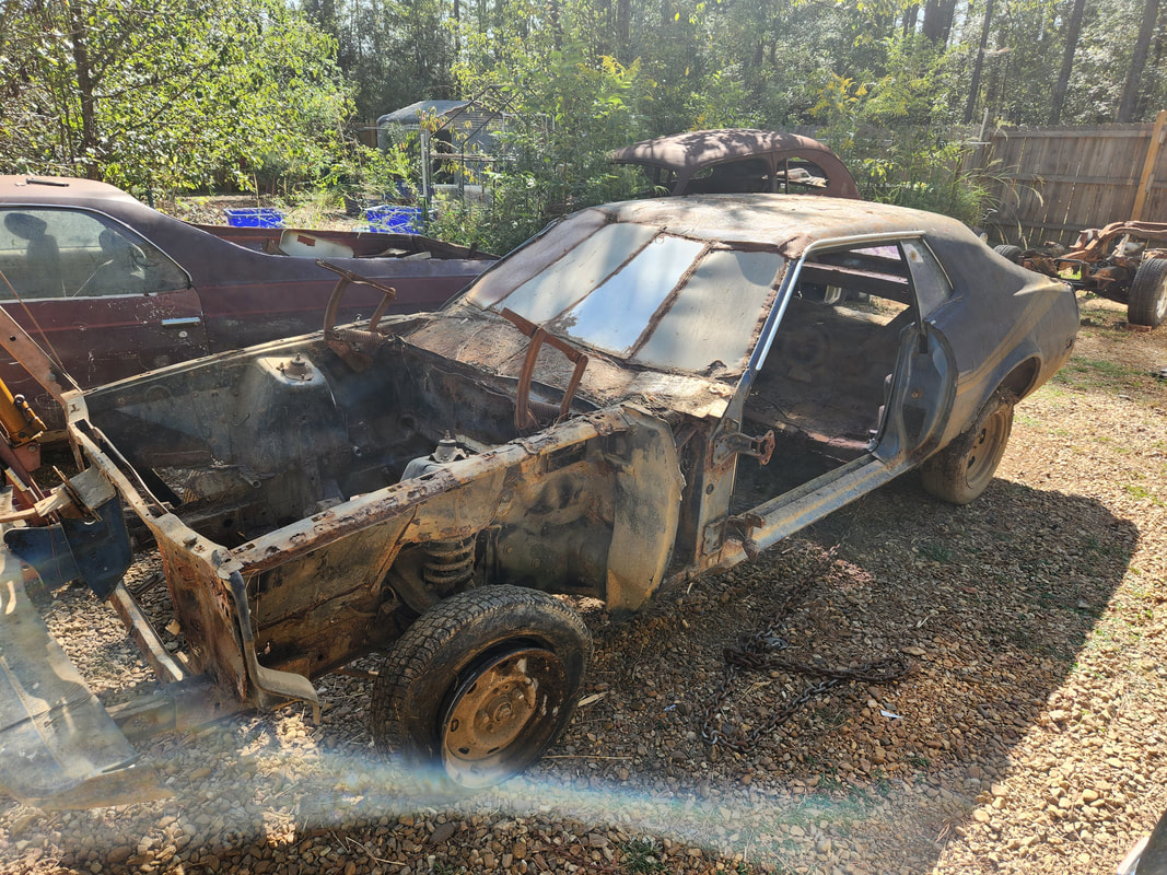
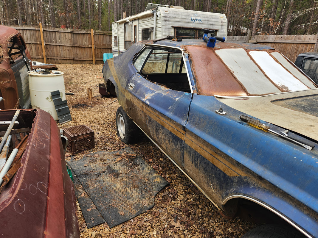
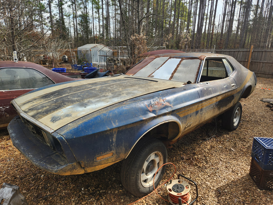
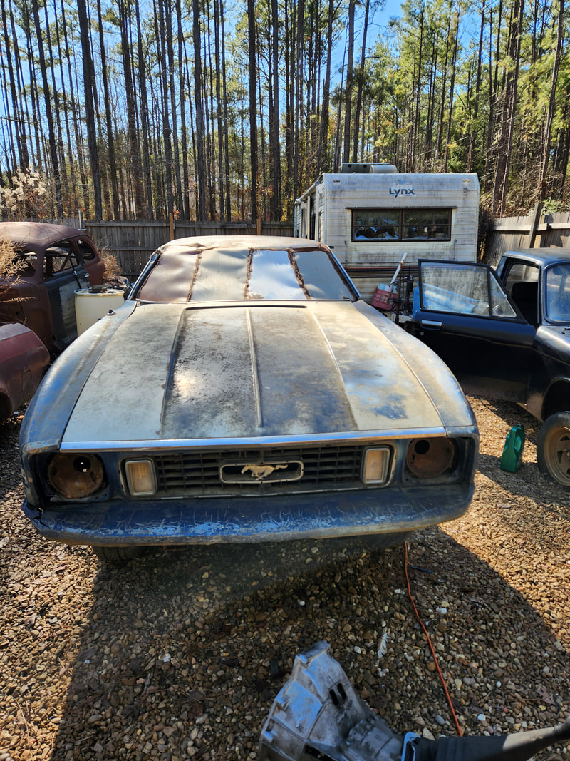
After a few years of service in the chicken yard housing chickens from babies up to adults, the Mustang Chicken Coupe has fallen into a state of disrepair as the sheet metal that was used for the cab and brooder areas rusted away in multiple spots. Even after a couple patch ups, it has gotten to the point where the chickens really didn't use the coop anymore, mainly retreating to the Minivan Coop, as well as the Toyota Chicken Truck, up until we closed it off to use it as a brooder coop. Now with plans to utilize the Toyota Chicken Truck's frame for a frame swap with the LUV, we also have plans to bring the Mustang Chicken Coupe, which is a 73 Mustang Coupe, back into car status and build it out as another Truckstang build, installing the body on another small truck frame. We recently picked up a short wheelbase S10 frame that we would use for this Truckstang build, as these frames have the same wheelbase as the vintage Mustangs, just like the SWB Ranger frames. The good thing about the S10 frame is that the front suspension uses the upper/lower control arm front suspension versus the swing arm style like the older Rangers do. This also opens the door for more modifications, whether I want to raise or lower the whole frame. I could very well lower the frame to bring the car down to an almost normal stature, versus the raised up ride height of Truckstang with its swing arm early Ranger front suspension. In the meantime I will have to move the Mustang Chicken Coupe from the chicken yard and cut out the floors and essentially everything that I welded or bolted in place when I built out the car as a chicken coop. One more thing, my plans are to make Truckstang 2 a bona fide Truck-stang, as the welded trunk lid will be cut out and the rear window and area cut out to make a carryall bed, essentially making a ute out of the body, giving the car some utility as well as uniqueness, and making it a true Truck-stang.
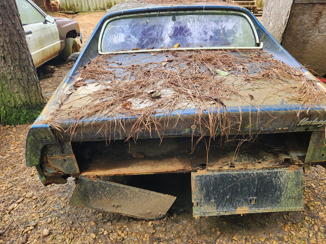
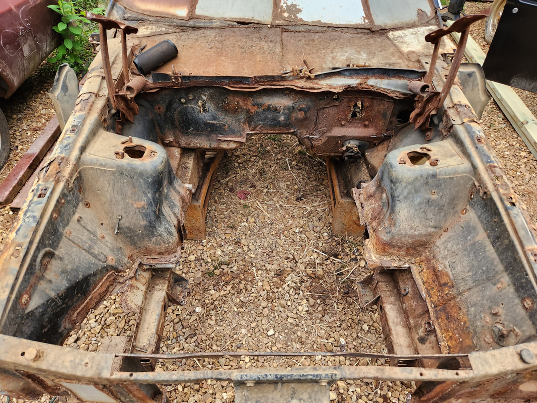
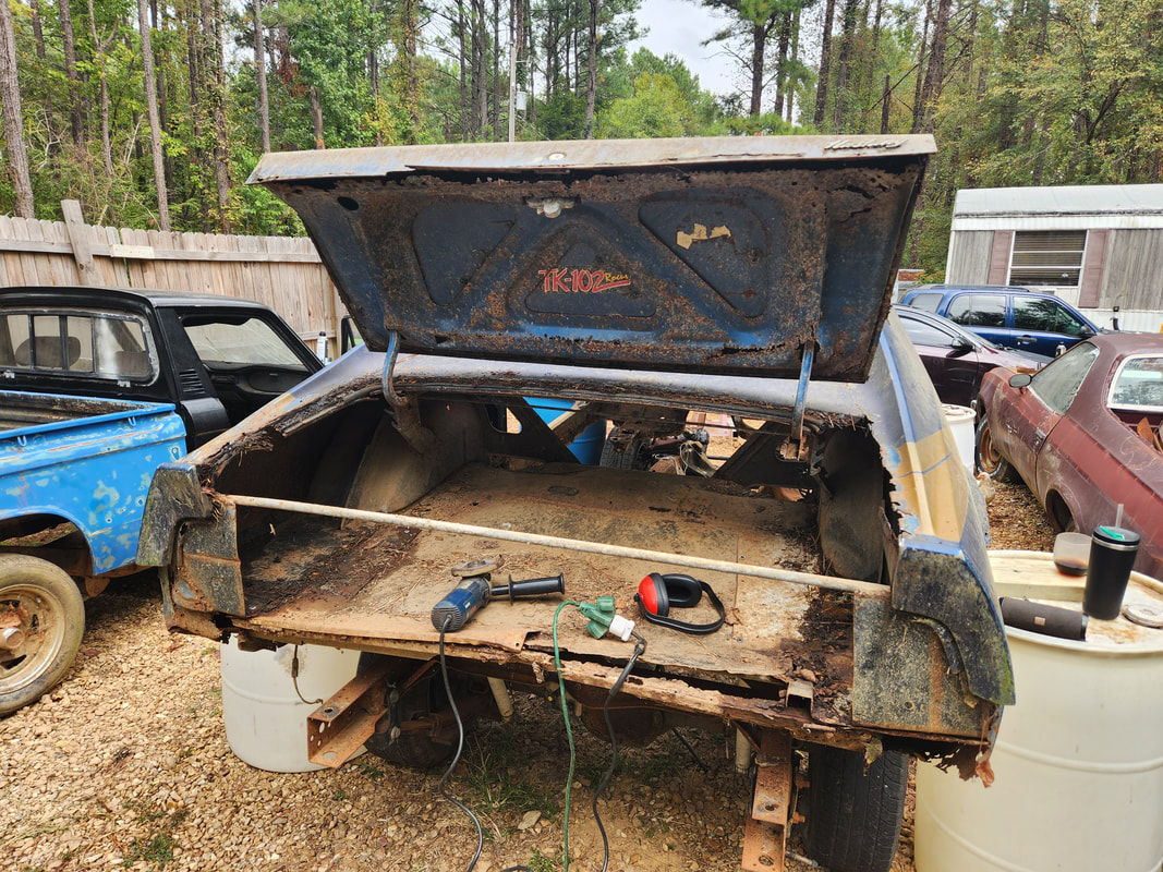
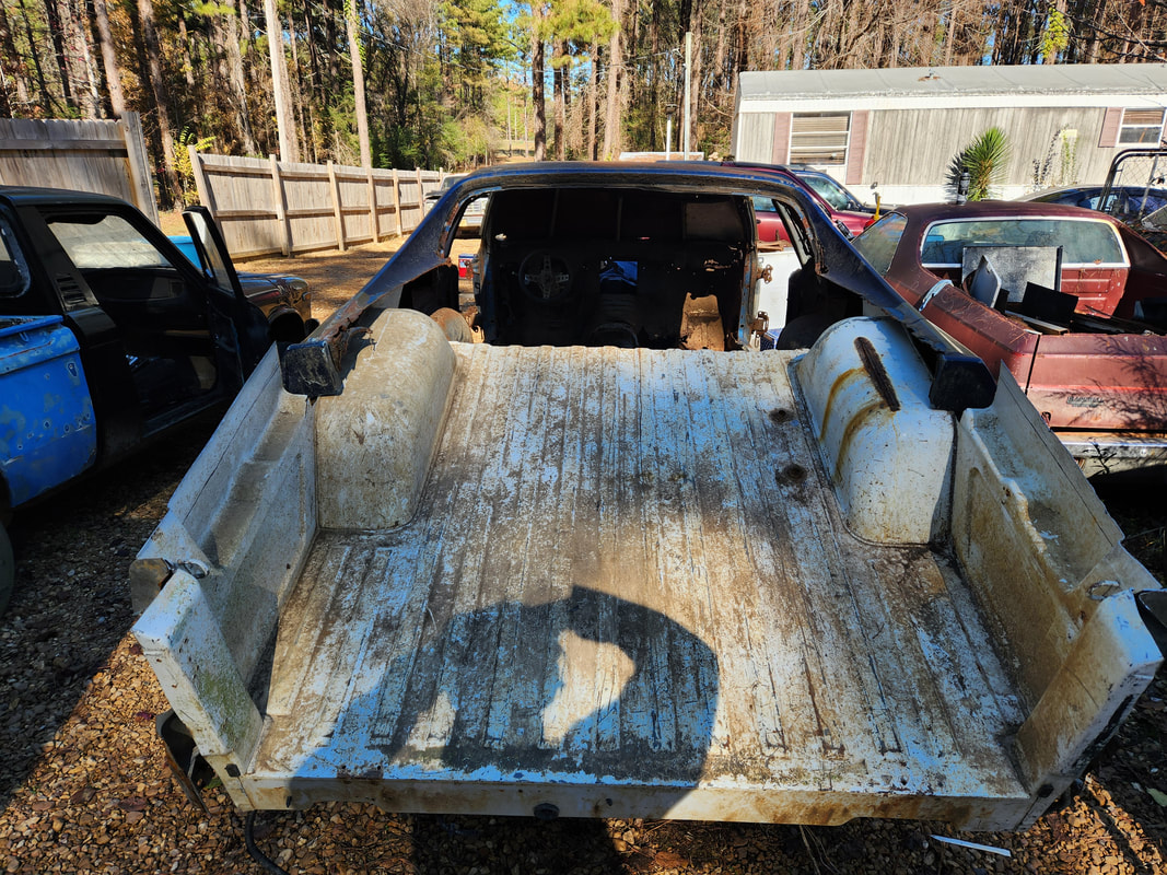
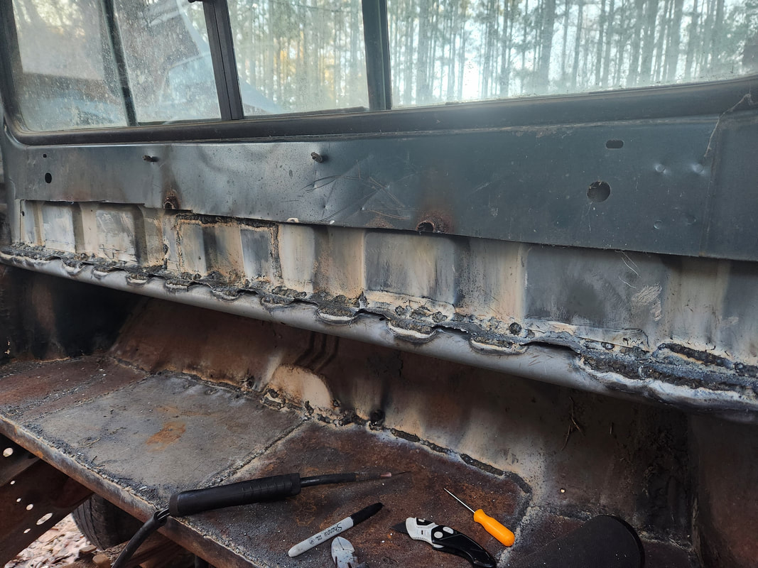
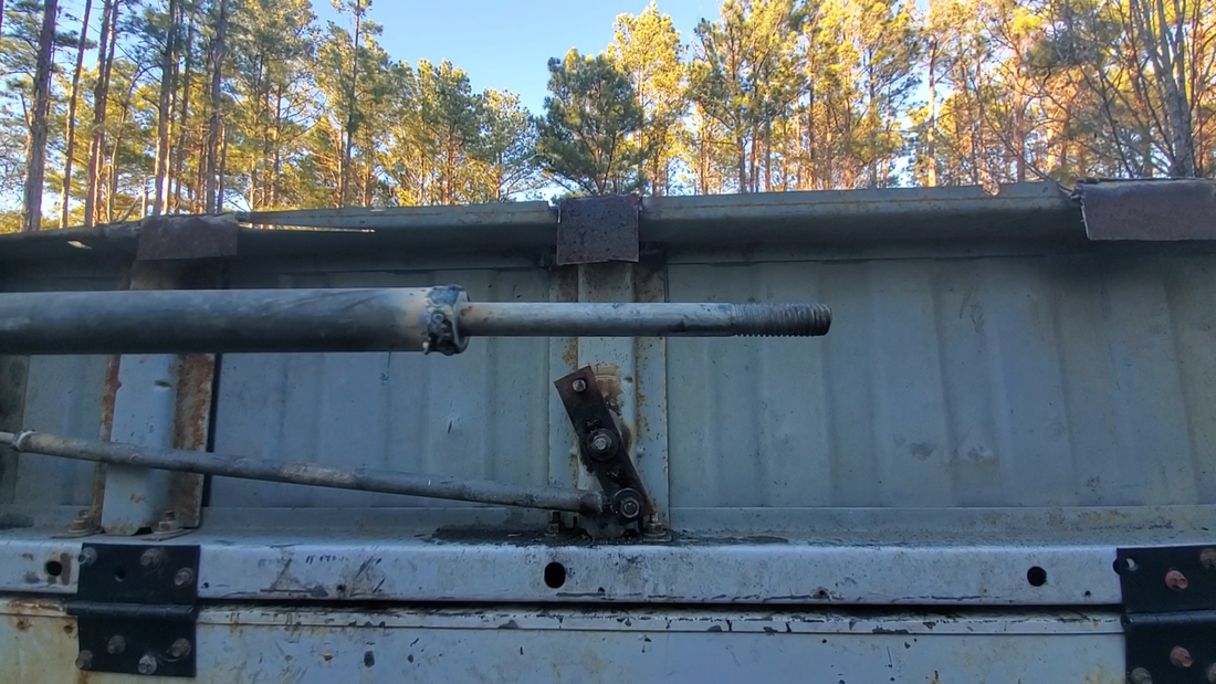
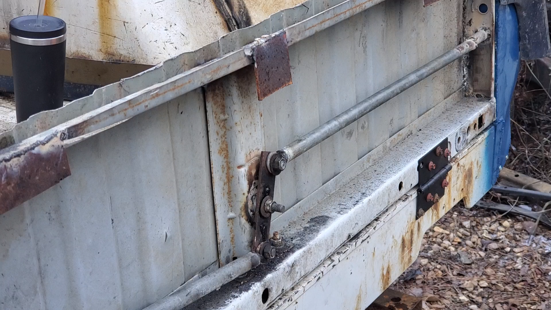
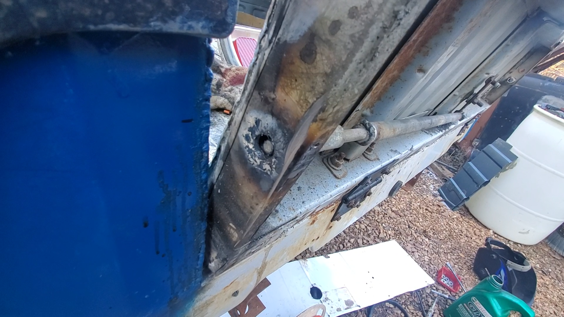
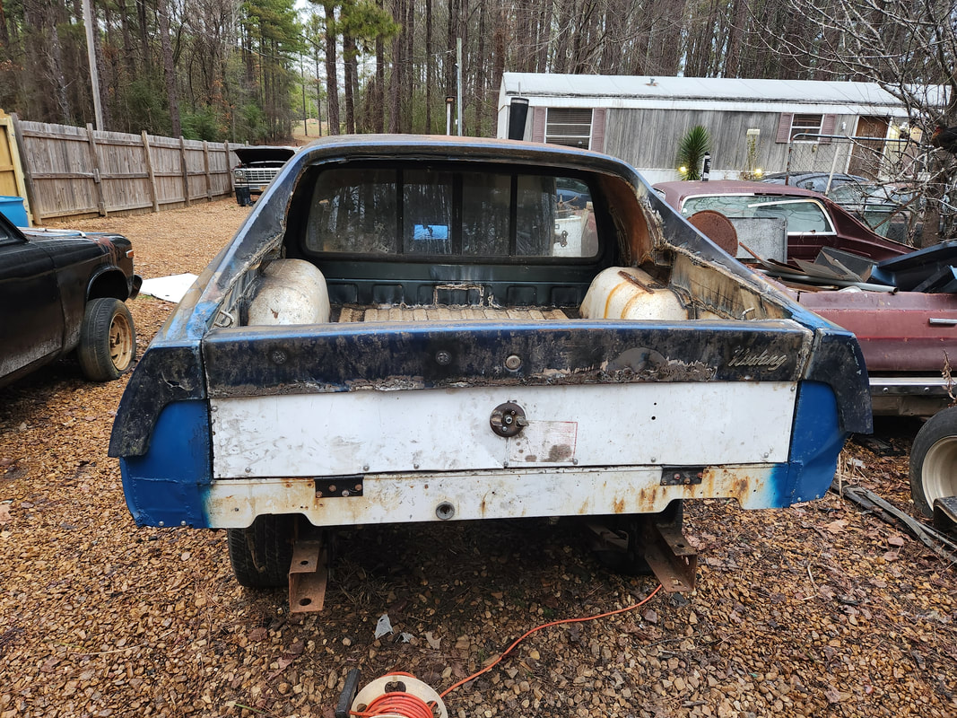
The rear of the old chicken coop showing the level of degradation of the metal that was used in the construction of the coop.
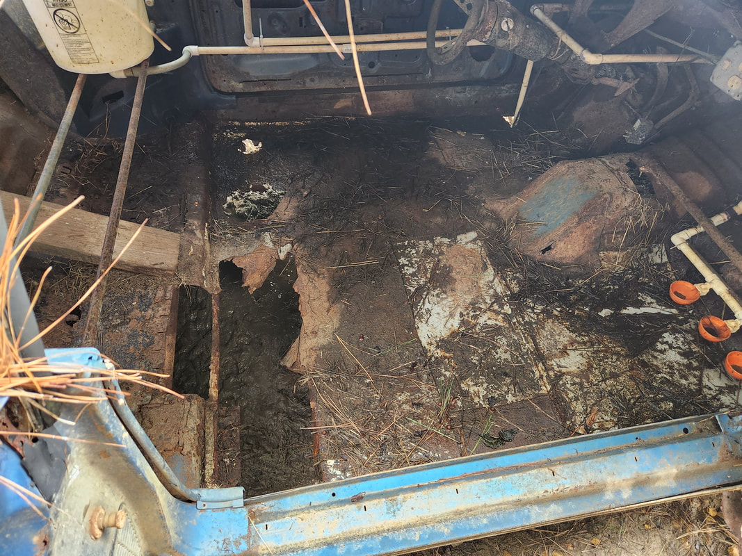
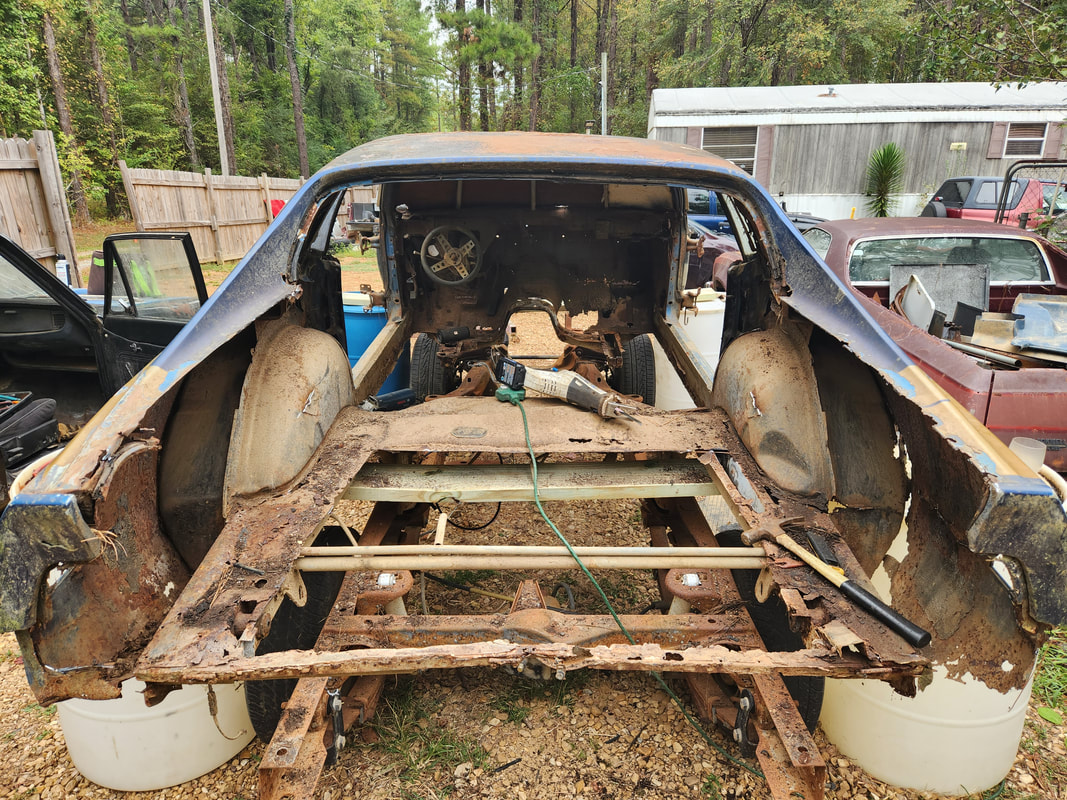
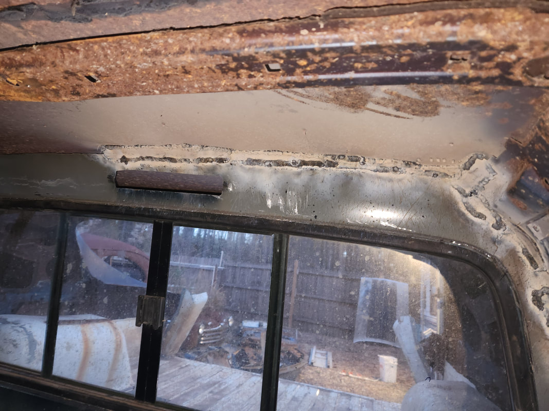
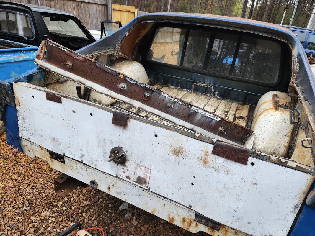
Large sections of the interior floor have rusted away, which is just as well, since all of this will need to be cut out, opening up the entirety of the interior. As with Truckstang, the entire undercarriage, including torque boxes and a portion of the frame rails and shock towers will need to be cut out. This build will be very similar to the first Truckstang.
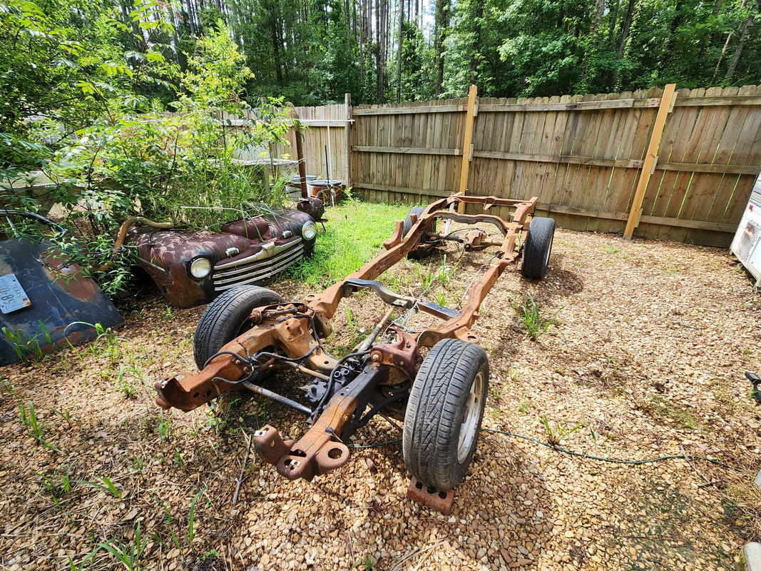
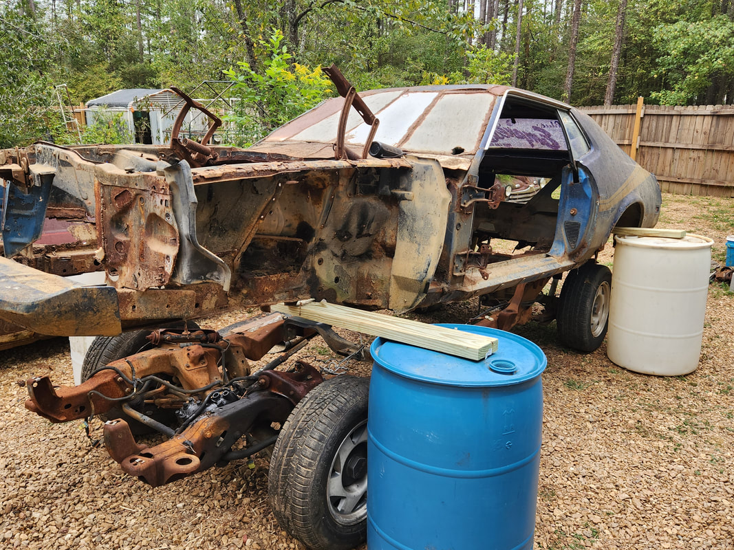
The SWB S10 frame we recently acquired for use in the Truckstang 2 build.
The first order of business is to break down the car, removing everything that can be removed, especially the material used to turn the car into a chicken coop. The doors, fenders, hood, etc all have to come out. The sheet metal and conduits used to make the floors in the engine bay and cab areas have to come out. All the plumbing and electrical hardware have to come out. Once the car is stripped as much as possible, it will be moved to the area where the S10 frame is staged at. I can then continue with the further break down so the body can be lifted up onto the drums and boards, just like Truckstang 1.
First the doors came off. Multiple bolts held the fender in place. One in the rear, several along the top, a few at the bottom front where the fender attaches to the valance panel and a few behind the headlight where it attaches to the core support area. Everything that can be removed has been removed from the car, body wise, now the next thing is the chicken coop related hardware. The engine bay has been cleared by removing the self tapping screws that held the sheet metal then the rest was cut out around the edges of the firewalls/shock towers/side panels. The plumbing has been removed from the engine bay as well. A few of the electrical components in the engine bay have been removed as well.
With all the old chicken coop stuff removed from the car, the next move was to pull the car from the chicken yard. With the aid of the tractor, we managed to pull the car body out and get it staged where we were able to push it in backwards, parking it in front of the S10 frame. With the car in this spot, I can begin the advanced disassembly. I jacked the car up and removed the front wheels, placing the set of metal ramps under the front subframes. From here I began the breakdown of the front suspension stuff, at first using the pair of spring compressor tools for the coil spring but then the 2nd time I just removed the nuts for the upper control arm and popped it and the coil spring out. After removing the upper/lower arms and spindles and springs, I removed the steering gearbox and tie rod assembly. Lastly I cut out the two crossmembers, the one that held the front of the stabilizer struts and the other one that connects the two shock towers. After some effort the latter was done, and I freed the engine bay area of everything that needed to be removed. Next I will be working on the rear suspension, cutting and removing everything to get the whole rear end and leaf spring assembly out of the car.
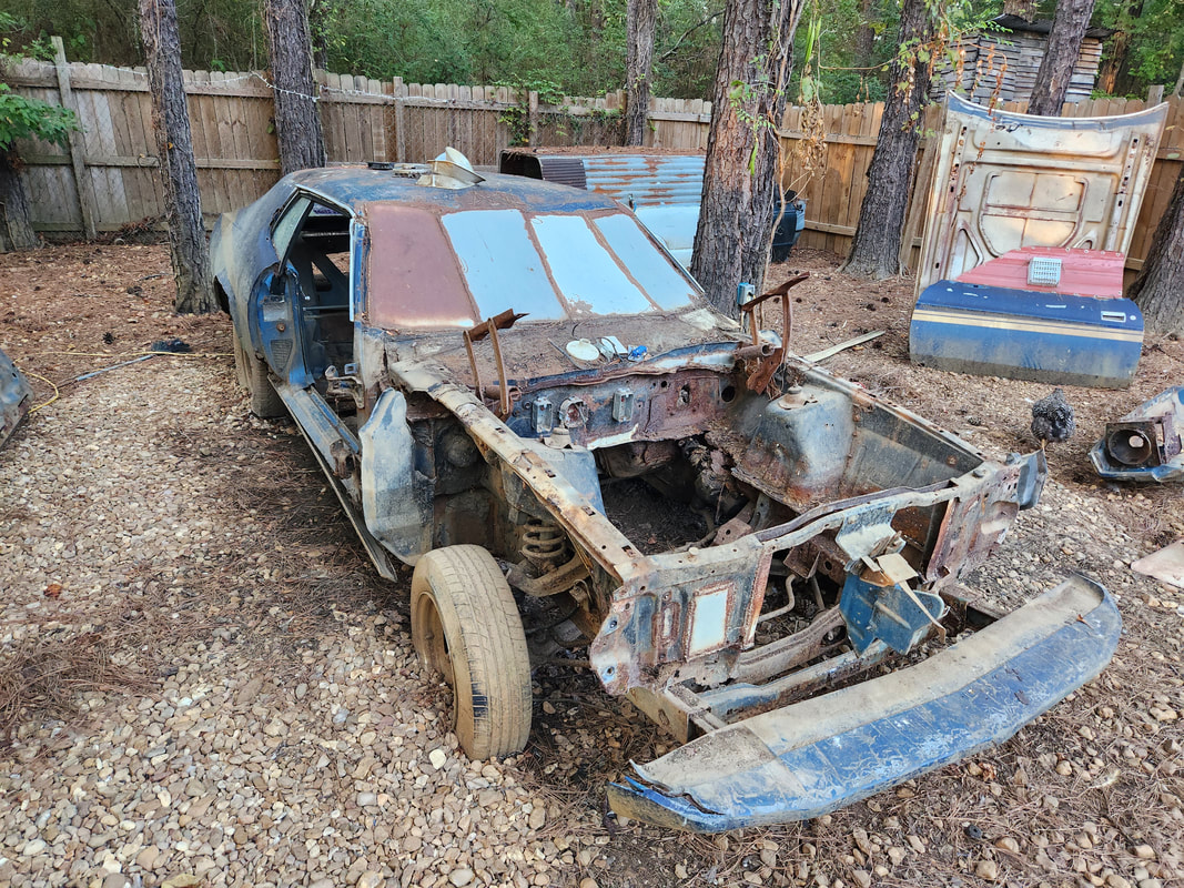
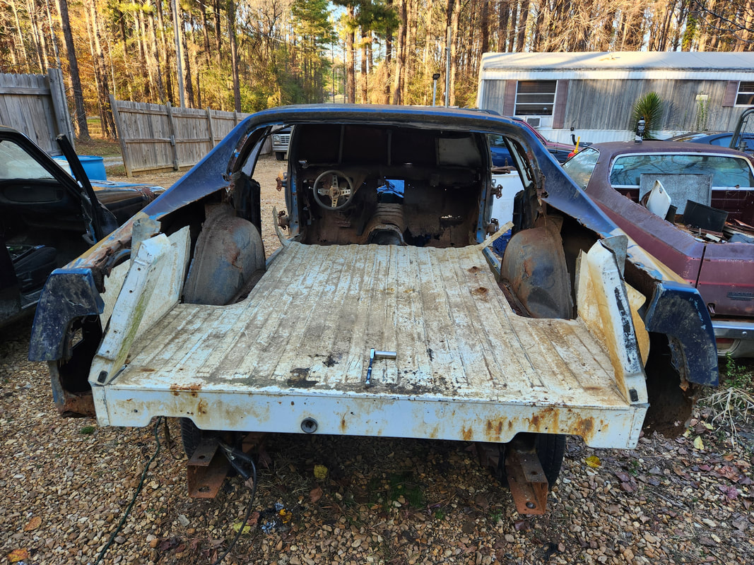
After pushing the car back into the yard, the car is in position so it can be further disassembled. Note in the upper right the S10 frame that is behind the car, ready to be rolled underneath when the body is ready for mounting.
On the left side I used a spring compressor to remove the spring while some of the bolts had to be cut to remove the rest of the suspension. On the right side I disconnected the upper ball joint then the nuts holding the upper arm in place, allowing me to knock the spring and arm out in one shot. I then used the grinder and saw to cut out the two crossmembers in the engine bay, clearing this area of everything that will need to come out.
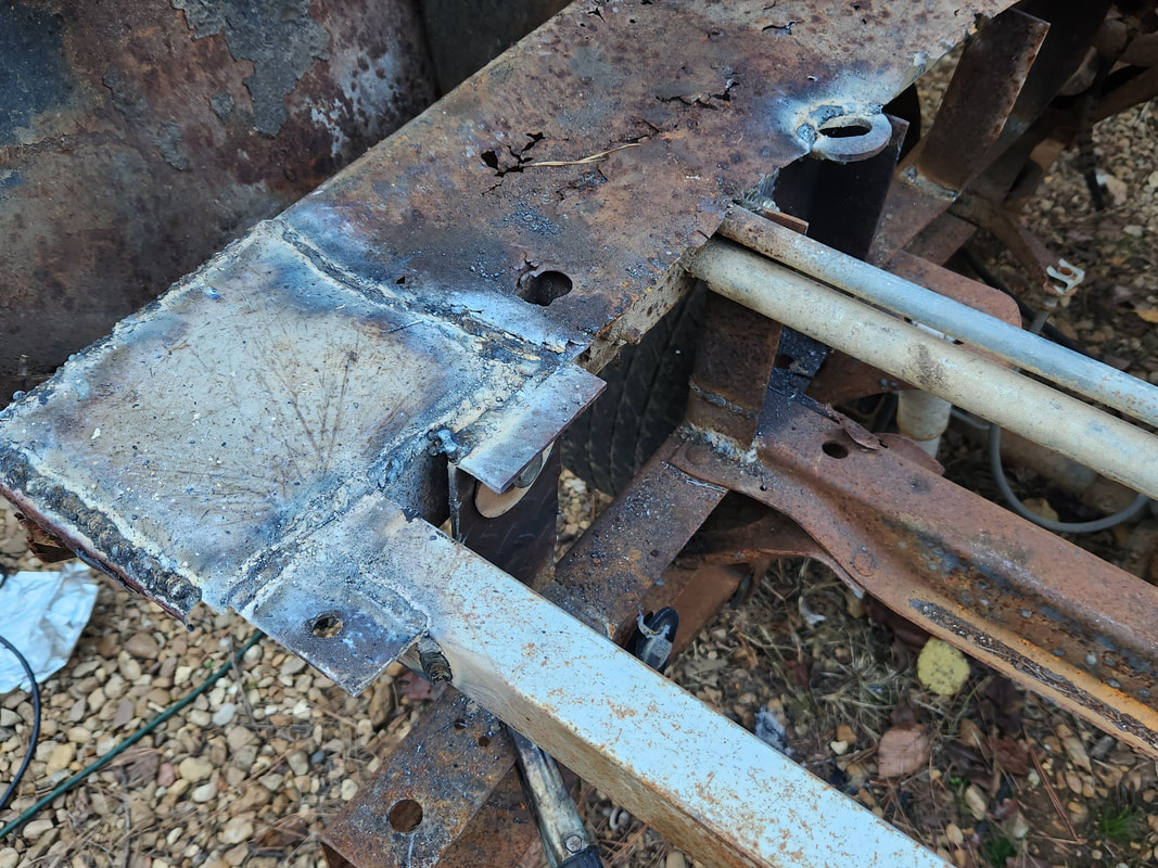
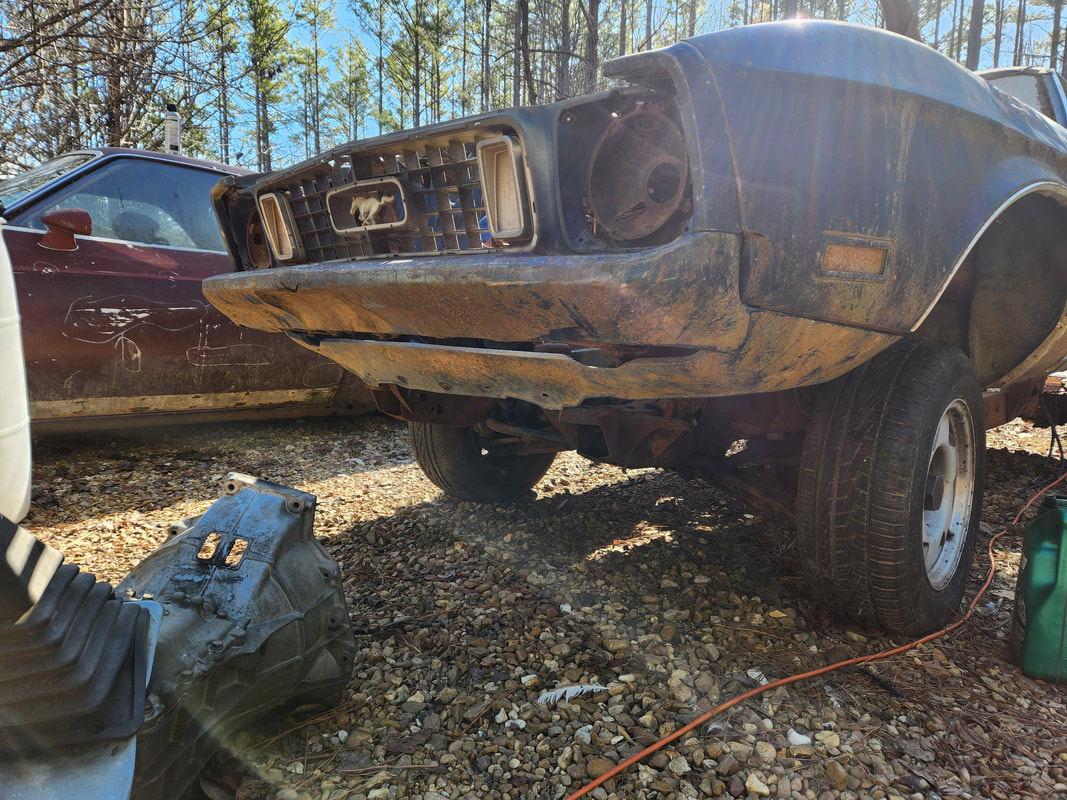
The next move is removing the rear end from the car. This involved removing the nuts from the rear shackles on the leaf springs, cutting the parking brake cables and brake line and removing the bolts holding the fronts of the springs in place. I had to cut out the rest of the floor at the rear of the cab to gain better access to the areas around the torque boxes. The rear of the springs was easy but one of the bolts at the front was frozen in place. I had to do some cutting around the torque box to get the spring free. I also had to cut the U-bolts to free the springs from the rear end so everything could be easily removed. I then used the engine crane to jack up the body, starting at the rear, just like on Truckstang. I should've known, but just like on Truckstang, trying to jack up the front by placing the boom under the bumper. I ended up only getting successful results by placing the boom above the bumper. Once the body was on the boards and drums, I was able to roll the S10 frame under the body to get an initial staging of the two components in order to see what will need to get cut out first.
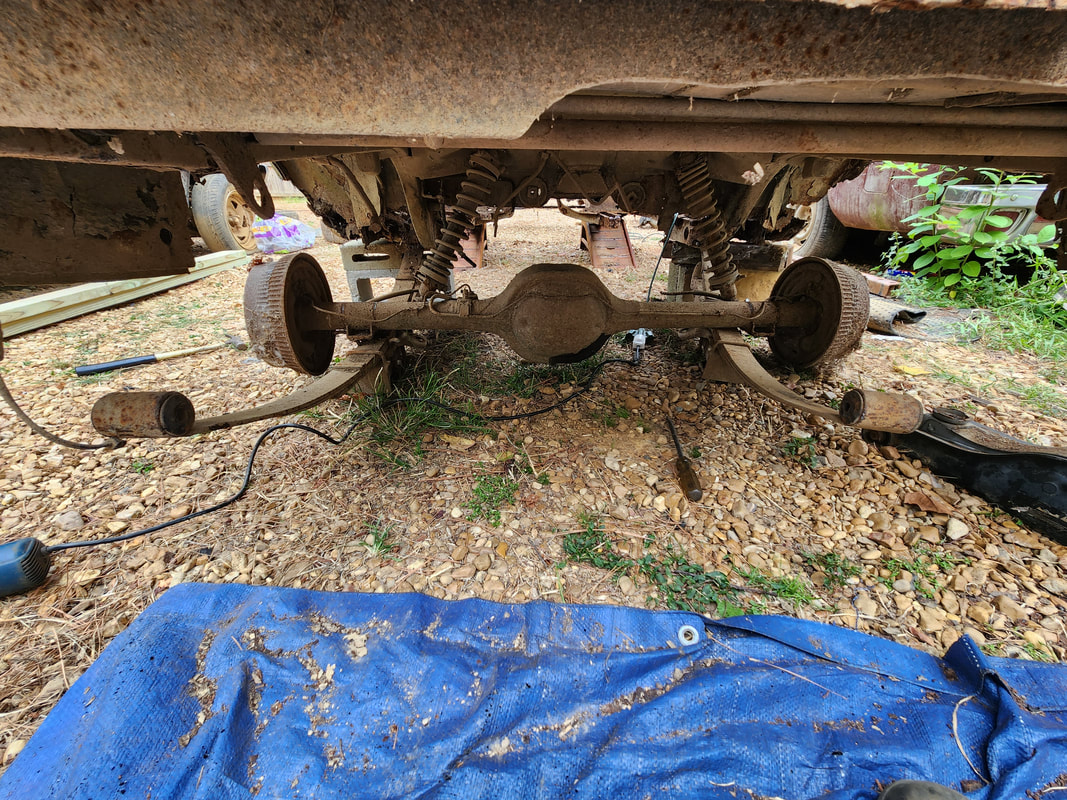
The rear spring shackles were easy to remove, but the torque box at the right front had to be cut and pried away to allow for the spring to be slid off the bolt which was frozen to the metal hub in the spring bushing. I also had to cut the U-bolts on the springs to separate everything to make it easier to pull the components out. The body had to be supported on ramps and blocks to hold it off the ground so the rear suspension and rear end can be removed.
With the body sitting on the drums and boards, I was able to roll the S10 frame under the body to stage the two components in order to see where I will need to begin the initial cuts to the subframe in the placement of the body to the frame. I do want to get a powerplant installed in the frame before I really do any serious work so I can make all my measurements and cuts and modifications around the placement of the powerplant.
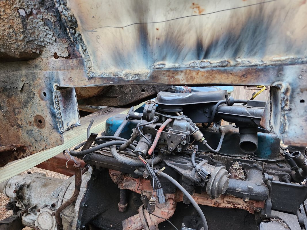
Since this car is going to be built out as a Ute, it only made sense to start with the rear on the beginning of the chop job. As a chicken coop, the trunk lid was welded shut and the taillight panel was cut out and two smaller panels welded in to create a hatch. The trunk floor also had to be repaired with welded in sheet metal which also had to come out due to rust. After cutting open the trunk lid and removing that, I removed the self tapping screws that held the sheet metal in at various points then cut the welds to remove all the added sheet metal. The rear panel was chopped, freeing up the rear window, which was then removed in one piece. The internal substructure was cut to allow for the full removal of the rest of the rear sheet metal. With the rear opened up fully, I turned my attention to the front, removing the shock towers in their entirety. I cut and welded in two patch panels made from salvaged appliance sheet metal. The next move will be the installation of a powerplant on the frame so I can continue nwith the fitment of the body around the powerplant, instead of guessing where to set the body.
Cutting the truck open to begin the chopping of the rear of the car. Most of the metal back here has to come out, not only because its from the chicken coop project but because a lot of it is rusting and will need replacement. The floor area will be replaced with sheet metal salvaged from the old S10 bed in the process of turning the rear into a pickup bed.
The trunk, sheet metal and rear panels are all chopped out and the rear window is also gone in the process of converting into a Ute. The pickup bed will be donating a lot of metal to finish this area like a truck bed.
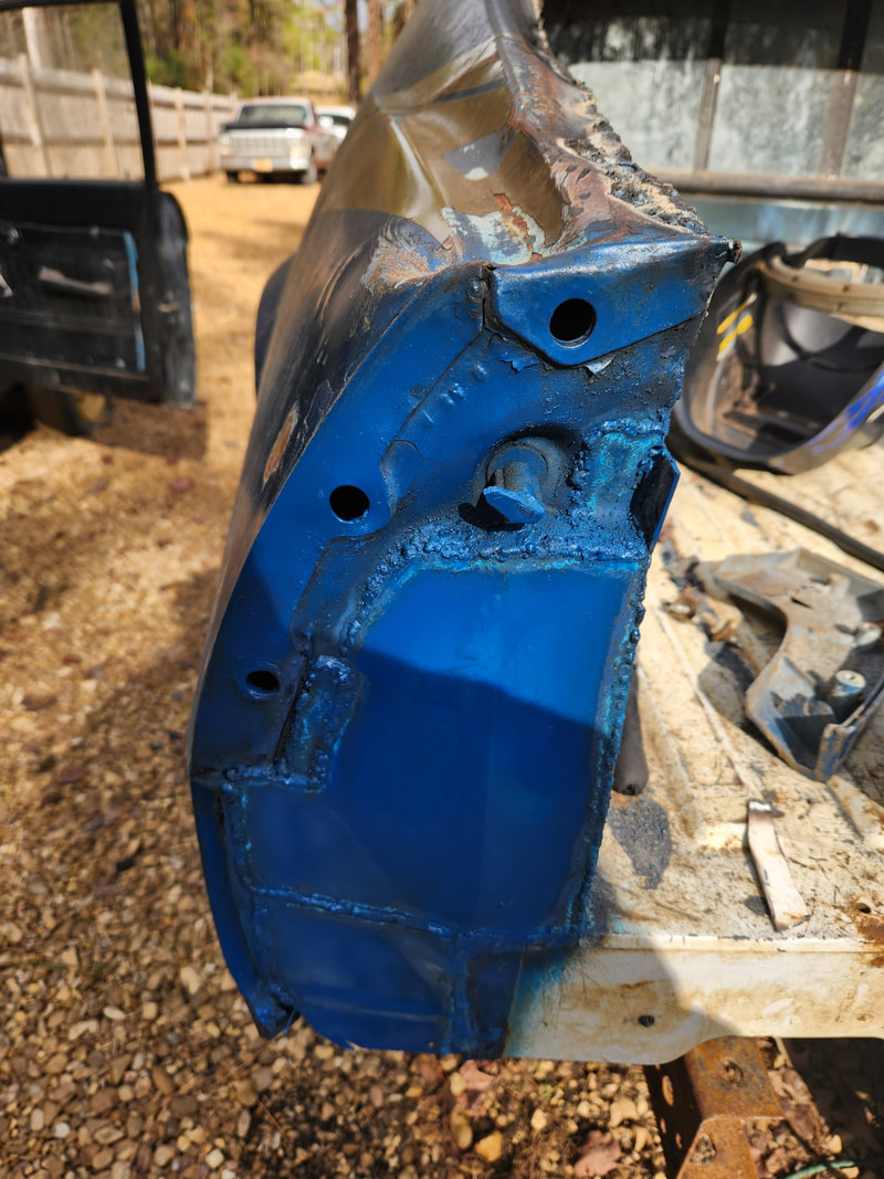
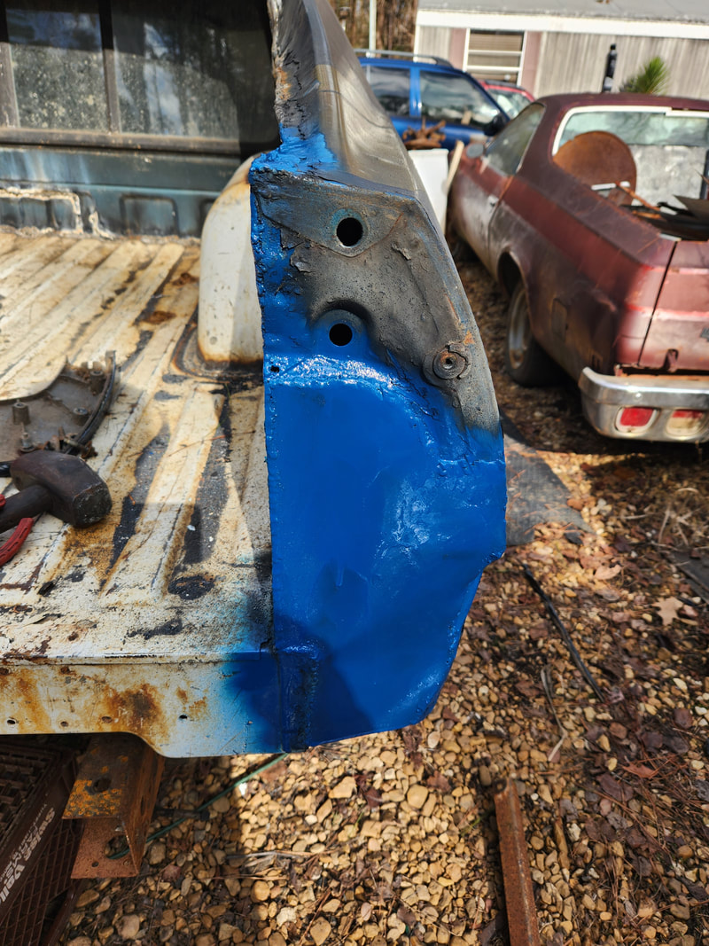
The old shock towers are chopped out in the front in order to clean up the engine bay area since they are not needed. All suspension components are on the truck frame so these bulky body components just take up space. They will be replaced with sheet metal just like on Truckstang.
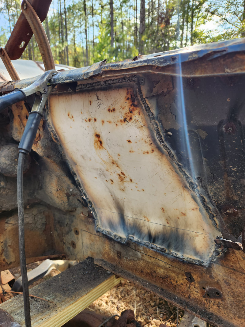
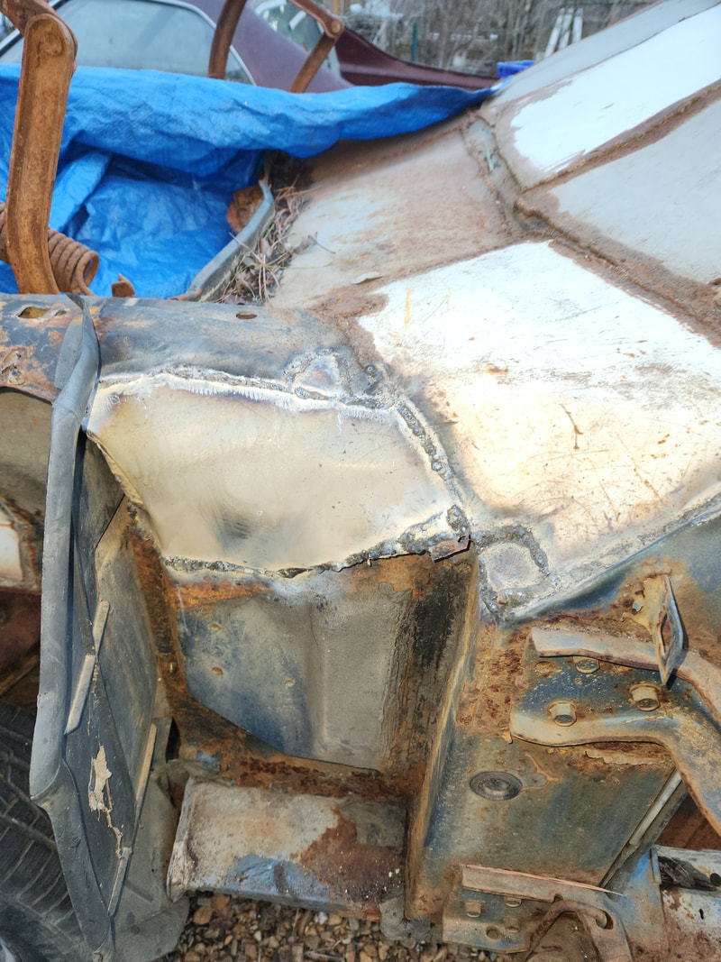
A large piece of appliance sheet metal was cut in half to yield the two pieces of metal to make the patch panels for the shock tower deletes. The sheet metal was outlined, cut out and bent to match up to the contours of the side panels on the car. The sheet metal panels are welded in place on the outside first, with multiple tack welds, then full welds filling in the lines around the hole until the whole thing is welded in. After getting both panels welded in around the outsides, I came back over the insides of the panels to weld them, reinforcing the panels.
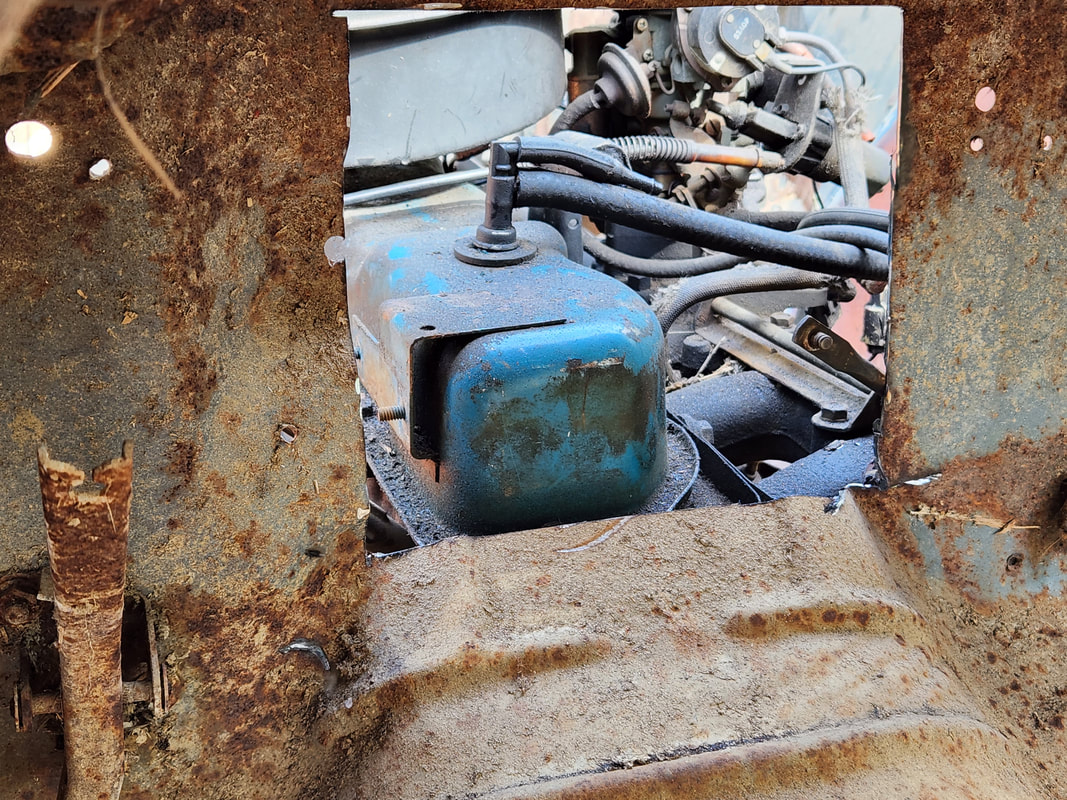
Going off on a tangent, we took a moment to grab us a 300ci 6 cylinder engine for the build. One of the good things about the big block 6 cylinder Ford engines, unlike the small block 6 cylinders, like the 200ci in Rustang, is the idea that the bellhousing bolt pattern is the same as the SBF V8's, so we can use one of the C4 transmissions we have laying around, along with the spacer and flywheel. After getting this engine, I got it staged in front of the frame and body where I can jack it up in place to mount in the frame later. I mounted the transmission and jacked the rig up so I can fabricate motor mounts, using the remnants of the mounts on the engine as well as the brackets on the truck frame. Once that was done I jacked up the body to roll the frame back under the body with the engine in place. From there I marked the spots on the front subframe rails that would need to be cut out so when the body is lowered down onto the frame, the front subframes would clear the upper control arms on the frame. At the same time I also moved the front board and drums more to the rear on the front subframes to completely expose those points to be cut out. Once the sections of frame rails were cut out, I cut small pieces from these pieces to weld in place to plug up the openings in the box metal of the frame rails. At this rate I can continue with the fitment of the body at the front of the frame.
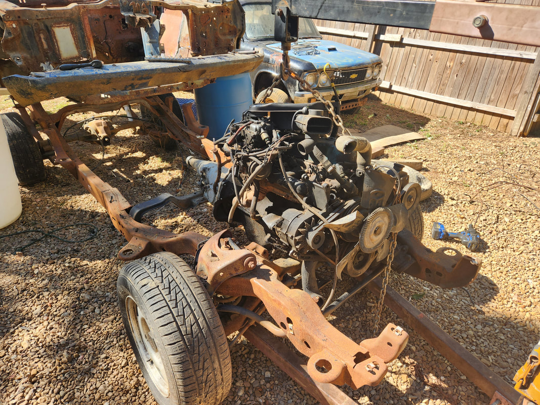
The powerplant is suspended over the frame after rolling the frame out from under the body. I had to add a couple bricks under the rear subframe where it sits on the rear board to raise the body up so the frame would clear everything under the body as I rolled it out.
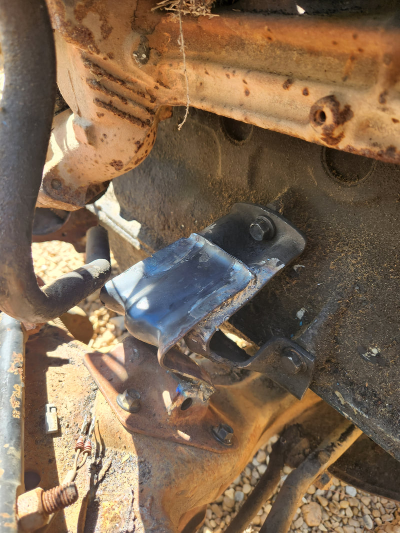
The motor mount assembly is bolted in place to the engine and the frame on both sides. One of the unique things about the V metal is the idea that it has a bit of a springy action that will hopefully take the place of regular rubber, so we might still have the ability to cushion the vibrations from the engine.
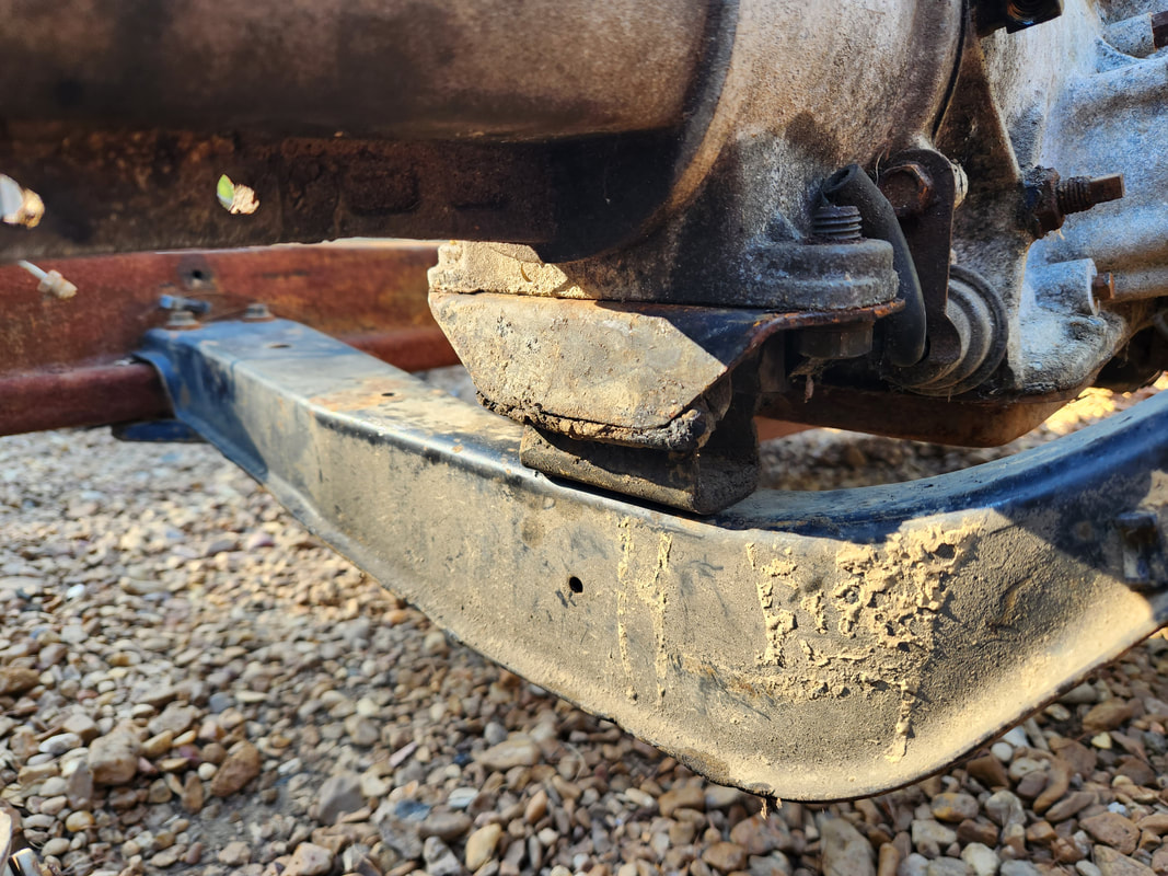
To do the transmission mount, I had to cut the mounting bracket on the S10 crossmember since it was touching the rear of the transmission oil pan. I cut a notch from the bottom of the crossmember to expose the inside of the crossmember where I can drill holes up through the top of the member to accommodate the studs on the transmission mount. On the underside I cut a section of metal which allowed me to drill holes through the top of the crossmember so the studs of the transmission mount can pass through.
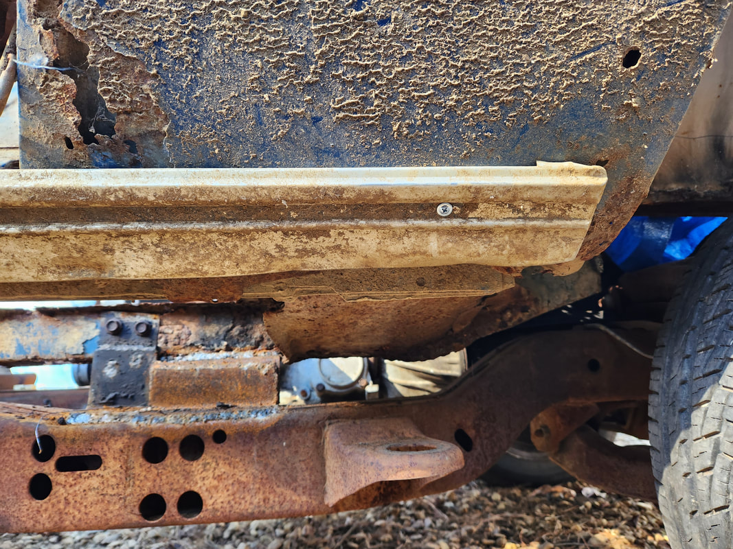
The front of the body had to be jacked up with the crane to allow the engine to clear as I rolled the frame back under the body. The front board and drums were moved to the rear of the front subframes to expose the section of subframes that will have to be cut out. The sections of subframe just over the upper control arms are cut out to allow the body to sit lower and closer to the truck frame. I borrowed some metal from the cut out frame rails to make the patches to cover the openings on the frame rail.
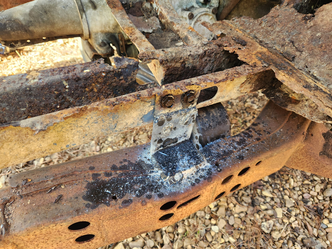
With our powerplant mounted and the front subframes cut and welded to fit around the control arms on the truck frame, I can move forward with mounting the body. The first thing that I did was utilize the pair of brackets on the front subframes that were used for holding the sway bar. Since they rested on top of the truck frame, I just drilled holes through the holes on the brackets and into the top of the truck frame. Since the truck frame metal is so thick at the top, I just tapped those holes for 3/8" bolts. From there, I moved to the back and hacked out the sections of subframes where they made contact with the truck frame and terminated at the torque boxes. This large section of subframe allowed the body to sit much lower against the truck frame. A set of brackets on the truck frame also sit higher and are at a position where it allowed for the mounting of a section of angle iron right on top of the torque boxes which also had them sitting right on top of those truck frame brackets as well. Holes drilled through the angle iron allowed me to place a pair of grade 8 bolts with washers and lock nuts through the angle iron and truck frame brackets. With that done I will move to the very rear and make up a set of brackets that will be welded to the truck frame but bolted up to the bushings where the rear shackle of the old leaf springs mounted at. The rubber will help cushion the mounts while still holding the body to the truck frame.
In the process of mounting the body down onto the front of the truck frame, I had to cut out this section of the firewall since the rear of the valve cover hit the firewall. I will have to weld in a patch panel that is contoured to go around the valve cover with clearance.
The rear of the body is resting with this section of subframe sitting on the top of the truck frame. This section of frame is cut out to allow for the body to be able to sit lower on the truck frame. After hacking out the sections of subframe, the body sits lower and is now using the torque boxes as the resting points on the truck frame. Also note the body mount brackets on the truck frame and where they sit compared to the torque boxes.
A long piece of angle iron is welded between the torque boxes. An extra piece of angle iron was welded against the other side of the angle iron, just between the main angle iron and the lip on the torque box for added reinforcement. Holes were drilled through the angle iron assembly where it sits on the truck frame body mounts to accommodate grade 8 nuts and bolts and washers to hold it down.
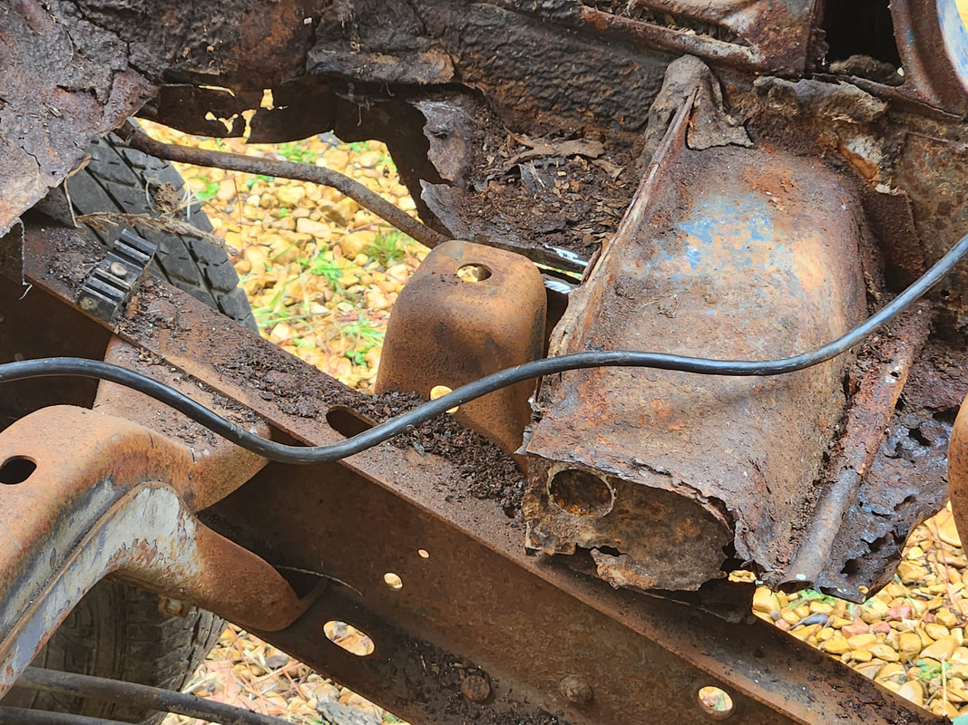
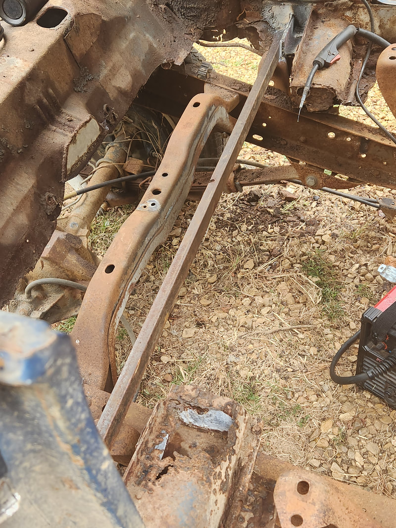
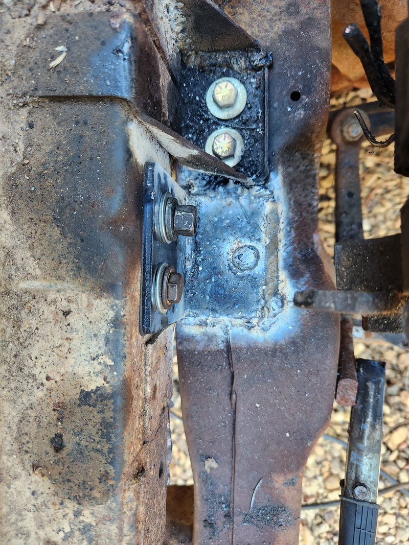
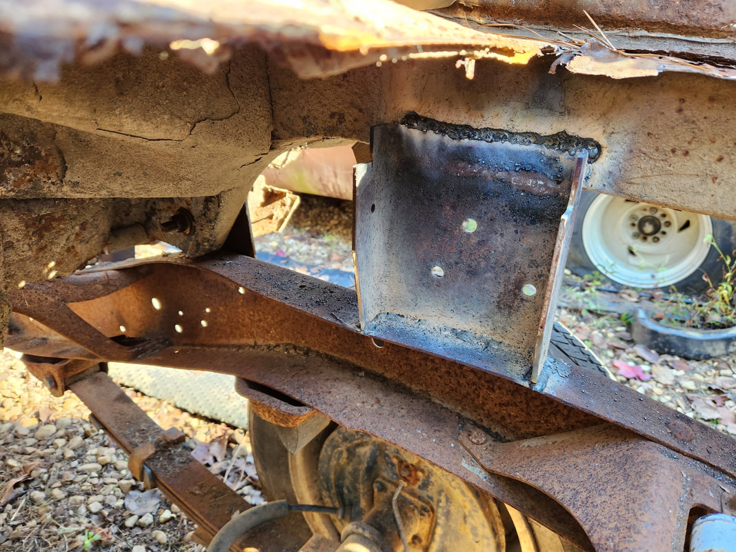
When it comes to the real stress points on the body, the real meat and potatoes is in the mounts at the very rear, front and middle, made from heavy metal brackets and bolted in place with grade 8 bolts. At the very rear, I used some 3/16" thick metal that I cut and welded in place on the truck frame and bolted to the old leaf spring bushings at the rear of the subframe. A little farther ahead where the axle is, I made a couple heavy plates that are welded to the truck frame and secured to the subframe using grade 8 bolts through the frame rails. In the cab at the front subframes, I made a couple more brackets that I welded to the truck frame and bolted to one side of the frame rail, using nuts and bolts to hold the two sections of sheet metal together. I couldn't go through both sides of the frame rail since I would've had to include some kind of heavy bushing that would keep the frame rail from collapsing in on itself as I tightened the nuts and bolts. I might correct this later before I start installing the floors. As for the very front, I took a couple heavy angle brackets that I welded to the truck frame and bolted in place with long bolts through the entire subframe. In addition to the sway bar brackets that are bolted to the truck frame, there is a double mounting at the front of the car between the truck frame and the body.
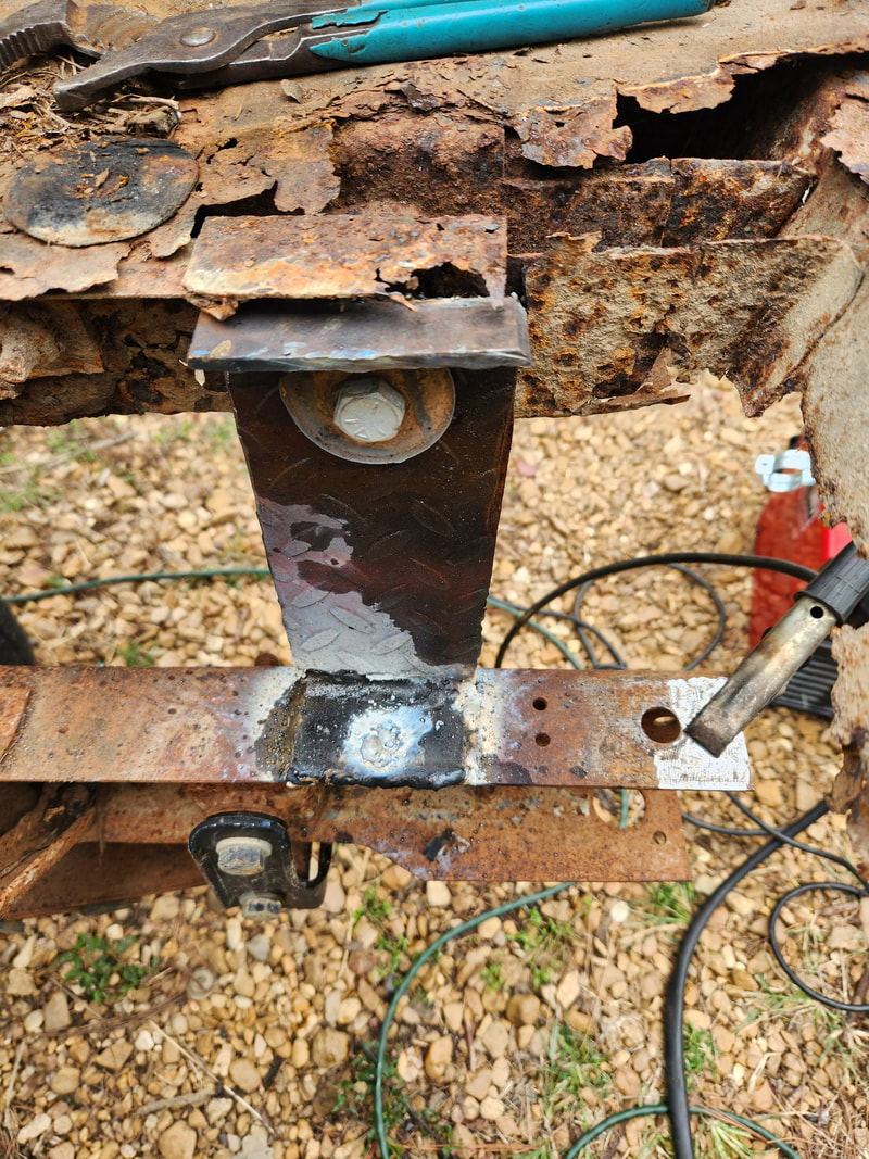
This bracket, made from some thick plate steel, is bent to create tabs at the top and bottom, with the bottom welded to the truck frame while the top serves as a bit of a lip for when the metal truck bed panel is attached in place. The bracket is held to the subframe through the old leaf spring bushing, which of course is extra strong to support the weight of leaf springs holding up a whole car while bouncing on a road.
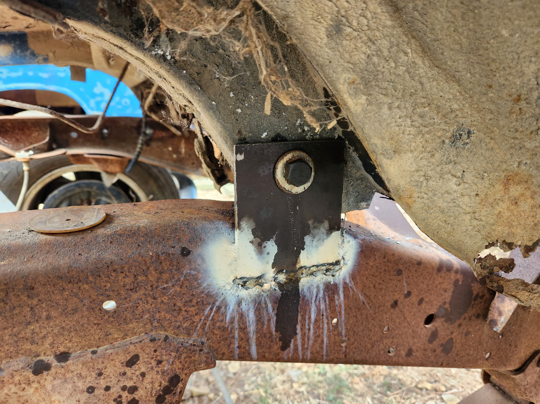
These brackets are made from more heavy metal that is welded at three points to the truck frame and bolted to the subframe through both sides with long grade 8 bolts. On the driver's side I did have to add a thick spacer bushing since the left subframe was off by a half inch.
These intermediate brackets, made from salvaged frame metal and heavy brackets, are welded to the truck frame to ensure strength while being bolted to one side of the frame rail, since these frame rails are relatively weak and rusty. Spacer bushings will have to be used to keep the frame rails spread apart and strong to allow the bolts to be torqued down properly without distorting or otherwise damaging the frame rails further.
At the very front, in addition to the sway bar bracket that is bolted to the truck frame through tapped holes, two heavy angle brackets are welded to the truck frame next to the sway bar brackets and bolted through both sides of the subframe with long bolts.
For extra reinforcement in the rear area where the truck bed will go, I cut some sections of frame rail from the old 51 Chevy frame to use for these brackets, one on either side, just over the axle. Even though both of these rail pieces are welded at the top and bottom, I did add a pair of nuts and bolts later on for redundancy.
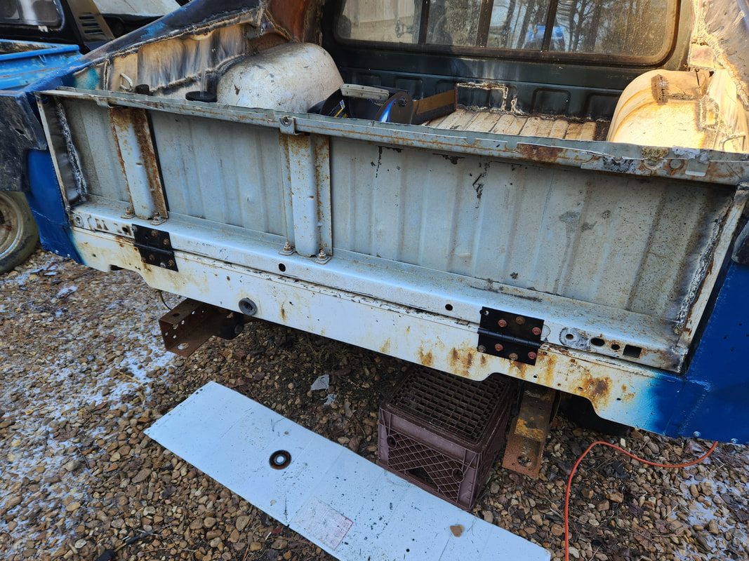
When it comes to the bed, in the fitting of the bed, I ended up cutting out the tire wells and the entire side panels, leaving just the bed floor and the rear third of the sides. I had to weld in a square tube across the very rear of the subframes, and added some metal around the ends of the subframes to reinforce the rails since the metal was rusty and weak in spots. i added some sheet metal over the tops of the subframes at the rear for added reinforcement since again, the metal was rusty in these areas. Since the bed has thread spots for mounting it, I welded in angle iron pieces on the square tube and over the axle body mounts to serve as anchor points to bolt the rear of the bed down. The front mounts were made using scrap metal cut from the old frame. After multiple episodes of measuring and fitting, I was finally able to install the bed and secure it with the four bolts. I will have to add some crossmember metal at the front of the bed to support the thing so when the rear cab panel is installed and welded to the bed, it won't stress those welds when something heavy is loaded in the bed. I will also have to weld the tire wells and side panels back on the sides as well as extra sheet metal to connect the bed to the quarter panels of the car to make everything look somewhat factory.
The very beginning of the fitting of the S10 bed, showing all the metal that is present.
The square tube crossmember is welded in the rear between the ends of the subframes. Angle iron is welded in place to serve as mounting brackets while a couple of tie down tabs that were cut off the subframe were welded in place to serve as mounting points in the middle of the bed. Also note the sheet metal welded on top of the rear subframe area, same goes for the right side.
The bed is mounted in place with the mounting bolts in place at the rear. The corner posts were cut to allow them to be folded down so the bed can be fitted in place. These posts will need to be welded back in place and trimmed down so they can fit within the quarters of the car.
With the bed in place, I turned my attention to the inside. I took a moment to weld a framework to create a trunk space of sorts just under the front of the bed that will sere as a storage area behind the seats. Later on I will have to add some spray foam to some hard to reach areas between the bottom of the bed and the old Mustang shock tower area so those areas will be closed in from the outside. Next I fitted the Ranger cab rear window panel, which required a bunch of trimming to get it to sit good enough where there wasn't too much dead space between the edges of the panel and the Mustang roof and sides. I cut the panel down to where it would be able to sit right on the top of the front lip of the bed, with a 1/4" of space at the edge. After welding this line I welded around the sides and the roof, which required a lot of filler pieces of scrap metal to close the dead space in. With the rear window panel in place I then trimmed the side panel pieces that were cut from the old S10 bed so they can be welded in place. This also included the cutting of a large piece of patch sheet metal that went over the inside upper quarter panel on the Mustang body to close those areas up. With the S10 bed side panel pieces trimmed and welded in place, taking care to keep everything symmetrical, I added a couple more pieces of sheet metal to cover the ends of the quarter panels where the taillights would've covered. These panels help close in the ends of the Mustang quarter panels with the rear of the body and the pickup bed, helping to further complete the Ute transformation on the rear of the Mustang body.
With a frame made from old conduit tubing and large pieces of sheet metal welded over each segment of the frame, a trunk space was created that will sit just behind the seats and just under the front of the bed, similar to how the Elco is made. The rear window panel is also trimmed and fitted in place, sitting just on the edge of the front of the bed. It is partially welded in this picture.
A closeup showing the full weld along the bottom of the panel as well as the trunk panels.
Small pieces of scrap metal were used to fill the dead spaces between the window panel and the roof and sides. A lot of welding was done to close all this in.
The tire well humps from the S10 bed are welded in place first before the side panels are trimmed and welded in place.
With the S10 bed side panels trimmed and a couple of sheet metal patches cut to fill in the upper quarter panel areas just behind the window panel, the sides of the bed are fully closed in. This also includes the corner pieces from the S10 bed, which also had to be trimmed to fit in place at the rear of the Mustang quarters.
More pieces of sheet metal were cut to fill in the open spaces at the rear corners where the taillight panel would've covered. The left panel was made of one larger piece and a smaller piece at the bottom that covered the lower portion where the bottom of the quarter curves inward to connect to the lower portion of the rear of the S10 bed. I sprayed Ford blue engine paint over the area to cover the welds to protect from future rust. Because these areas are welded up, access panels will need to be made for the bottom of the quarter panels to close in those areas. They have to be removable since I need to be able to reach inside to install the bolts to hold the old Mustang quarter extension pieces later on.
The right side was made with one piece of sheet metal but the same rules apply as with the left side. This side is fully overed with paint as well and will get an access panel underneath later on.
Since the rear corners have quarter extensions that have bolts that apply from the inside, I needed to leave the bottoms of the quarters open. To fix this problem, access panels were made from sheet metal and held with sheet metal screws. With the quarter extensions in place and the access panels secured, I moved on to making the tailgate. This was made with the front section of S10 bed I chopped off during the fitment of the bed. I welded sides to the panel to help in closing the tailgate in and attached the thing to the bed with large hinges held in place with self tapping hex head screws. I made a latching assembly with scrap metal, operating in the same way as a regular truck tailgate. The knob that rotates to pull the latches in and out is centered on the tailgate to mimic the Mustang fuel cap that would've been in this same location originally. I cut a piece of sheet metal to serve as the skin for the tailgate as well, cutting a large hole to allow for the latch mechanism to be open for the knob to be attached. As for the top of the tailgate, I cut the back end of the old trunk lid, welding bolts to the inside to hold the panel in place to the tailgate. Extra sheet metal was welded to the inside end of the trunk lid and the sides to close in the open spaces around the panel and the tailgate. With the entire tailgate done, I moved forward, welding some patch metal around the top sides of the inner body where the ends of the firewall and the wiper panel are, as these areas rusted out enough to leave large holes. With that all done I can move forward to getting the rest of the mustang body reassembled.
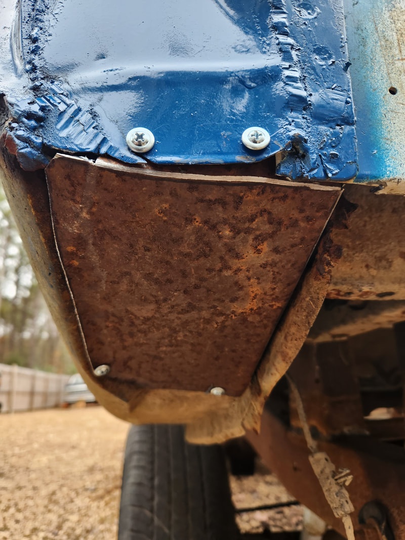
One of the access panels cut from scrap sheet metal and secured with sheet metal screws to cover the large hole under the quarter panel. This allows for access to the bolts that hold the quarter extensions to the rear of the quarter panels on the body.
The tailgate, after trimming down from the leftover piece of S10 bed, is secured to the bed with large hinges and self tapping screws. The sides were closed in with small pieces of support rails that were cut from the bottom of the old bed.
A closeup of one of the latching rods that make up the latch assembly on the tailgate. The rods are made from a long piece of 1/2" conduit with a long bolt welded in one end as seen here and an eye bolt welded on the other end. The rotating lever is seen in the background with the other rod in place.
The rotating lever is made up of a piece of flat steel with a center hub made from a bolt welded to the tailgate to serve as a fulcrum. A nut and washer holds the lever in place. Two more bolts are welded to the ends of the lever to serve as attachment points for the eyebolts on the latch rods so when the lever is rotated, they will pull the rods in to unlatch the tailgate or push them out to latch the tailgate. The rods are guided in and out with small pieces of conduit welded on the sides of the tailgate, with holes drilled through the sides so the rods can pass through. Holes on the corners of the bed allow the rods to insert to latch the tailgate in place.
A closeup of the outside showing the side of the tailgate with the hole where the rod passes through.
The knob for the latch is made from a truck body bushing cap, with tabs of metal welded on either side of the center hole to serve as tabs to grip to allow for rotating of the knob. The large skin of the tailgate is made from a large piece of appliance sheet metal cut to fit. Three large sheet metal tabs are welded to the top of the tailgate to catch the top of the panel while holes along the sides and bottom allow the rest of the panel to be secured with sheet metal screws. The trunk lid lip is modified by welding long bolts inside, which pass through holes drilled through both the skin of the tailgate and the inside of the tailgate. The bolts are held in place on the inside with washers and nuts. A lip of sheet metal is welded to the inside of trunk lid as well as on the sides to close the open spaces between the trunk lid and tailgate. Holes drilled through the sheet metal and the top of the tailgate allow for the rest of the trunk lid to be secured with sheet metal screws.
The trunk lid is secured to the top of the tailgate, lining up with the quarter panel extensions, maintaining the original lines of the Mustang rear. The lock face in the trunk lid lines up with the latch knob, which sits where the original fuel cap would've been. We even managed to keep the Mustang logo on the right side. A bunch of rough welding patches were done on the inside of the tailgate as the bottom most part of the lip was rusted badly.
These areas of the inner body where the wiper panel terminates were rusted away and needed to be filled in with welded scrap sheet metal to close the open space up.
With the patches made over the inner areas outside of the firewall, I got down to reassembling the body. Of course the panels on the car are in various stages of decay or damage since some panels suffered impacts from trees while some just have the normal Mustang rust that these cars are known for. Since some of the fasteners were rusted and broken, I had to substitute nuts and bolts where those fasteners were missing and in some areas had to actually take more bootleg measures like drilling holes to apply long wood or sheet metal screws to hold the ends of some of the components down. The grille was especially bad since all the plastic tabs for bolting the thing down were broken. The mounting tabs for the bottom rear portions of the fenders were also gone so screws were used to hold these ends of the panels in place. In the case of the doors and hood i had to take a moment to make minor adjustments to get the panels situated where they will open and close properly, or at least as close to true as possible, given the circumstances with these compromised components.
The passenger side fender and door are hung after adding all the fasteners and making the adjustments necessary to allow the door to open and close without binding against the fender. This door is one that took a hit and has a serious dent on the top of it so this door will need more work later on in order to get it where it will even accommodate a window.
On the driver's side the fender is what got hit by a tree. I was able to knock the dent out of the fender as much as possible so its not too unsightly. The door didn't take too much to get it to line up properly, for obvious reasons.
The hood took a couple attempts to get it lined up right where it sat even from front to back and be able to close properly or at least as close to properly as possible. The grille is in place after having to drill holes in four spots around the top and bottoms of both headlight buckets to allow me to apply long wood and sheet metal screws. Until I decide to source a replacement grille, this will have to do.
The front valance panel was one of the only things that went in pretty smoothly. The bolts along the tops of the panel still required me to reach around through the fender to get the tools in there but once snugged down, that was it. The hood latch was attached using the stock fasteners at both the grille and valance panel. Only other thing I had to do was slightly bend the bottom of the middle to allow for clearance at the front of the truck frame.
The rocker panel trim pieces had to go on in the same unorthodox manner with screws applied through holes drilled through the pieces and into the rocker panel. Again, all these pieces were compromised through rust and physical damage so most of them were not able to be secured in the "stock" manner.
