THE 1976 CHEVY EL CAMINO
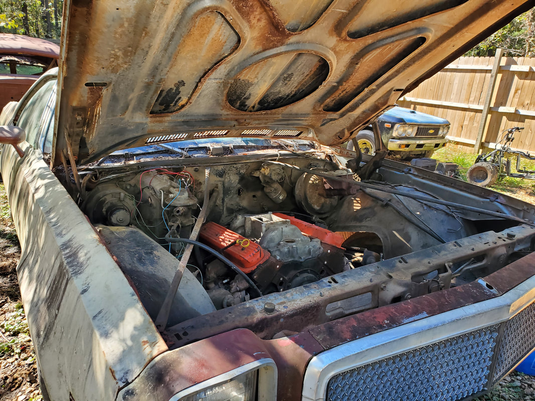
This little project is one that we had for quite some time and had actually done some work on prior to my recording it in this section of the TIC website. This is a car that started its life in our hands as a mere body with a bunch of parts. We actually picked this car up from a local auto shop for a mere $300, delivered to our door, title in hand. It was of course missing a few odds and ends but still, we got an El Camino for $300!
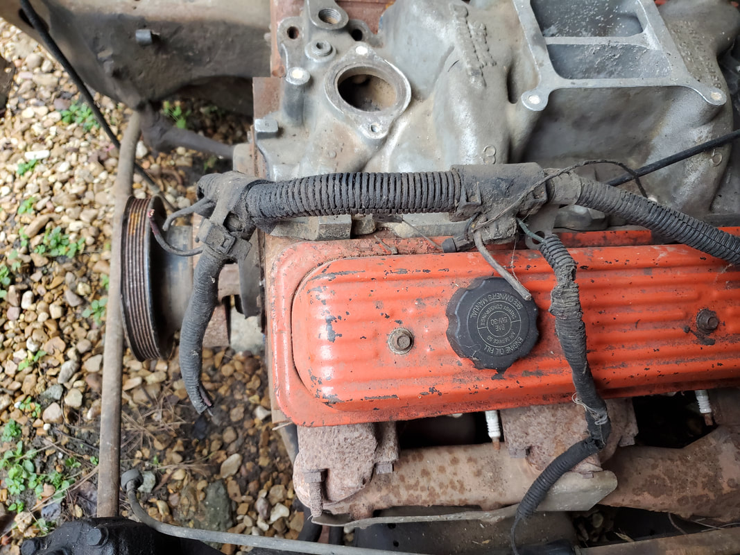
One of the first things that I did was pick up a used engine and a transmission that was supposed to be a rebuild and drop these two components into the car. Of course with the car being a SBC car, the whole powerplant went in smoothly, motor mounts and all. I also had stock exhaust manifolds that I put on the engine since I wasn't really keen on using headers. I will have to cut a couple of flanges from another SBC car/truck to use on these exhaust manifolds in order to build the exhaust system when I get to that point in the project. As for the transmission mounts, since the crossmember was one of the missing pieces, I had to fabricate one out of angle iron to use temporarily to hold the transmission up. As for the details on the powertrain, I installed a 305 that I helped pull from an early 90's Chevy truck and the transmission is a 700R4 that was sold as a rebuilt unit. I wanted the 700R for its overdrive gear as this would make the Elco a more economical daily driver especially on the highway. After doing this work, the car sat for a while, parked in the same spot along the driveway, collecting pine needles and crap in the bed.
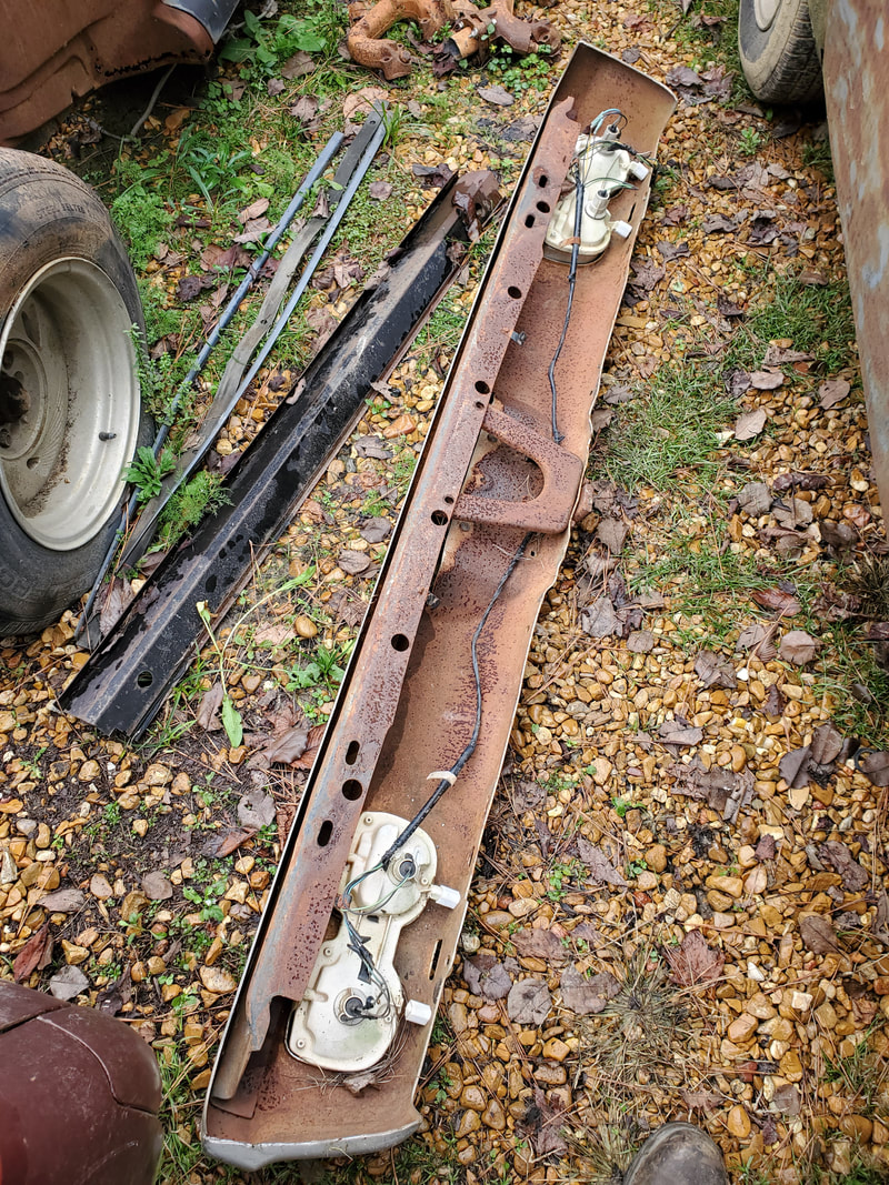
Fast forward to today and I decided to resurrect the project, as far as doing anything on the car goes. I figured that anything I can do on the car that doesn't involve spending any large amount of money would be worth it in order to get farther along in the project so even if I do put the project on pause again, I can at least know that there isn't much left to do in order to finish it. What I'm really looking at here is reassembling the car using the loose parts that came with the car along with some extras I managed to pick up from a past trip to Texas. I managed to pick up a replacement transmission crossmember and a rear bumper, which was also missing. That bumper was worth more than what I paid for the car as its the bumper with the integrated taillights. Luckily I found both pieces from the same guy for a little over $100. Taking these parts along with the rest, I can start getting the body together.
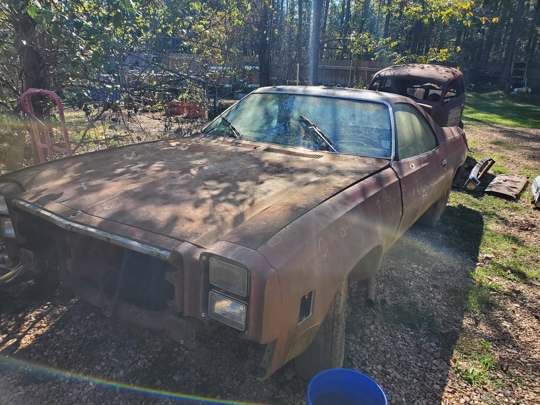
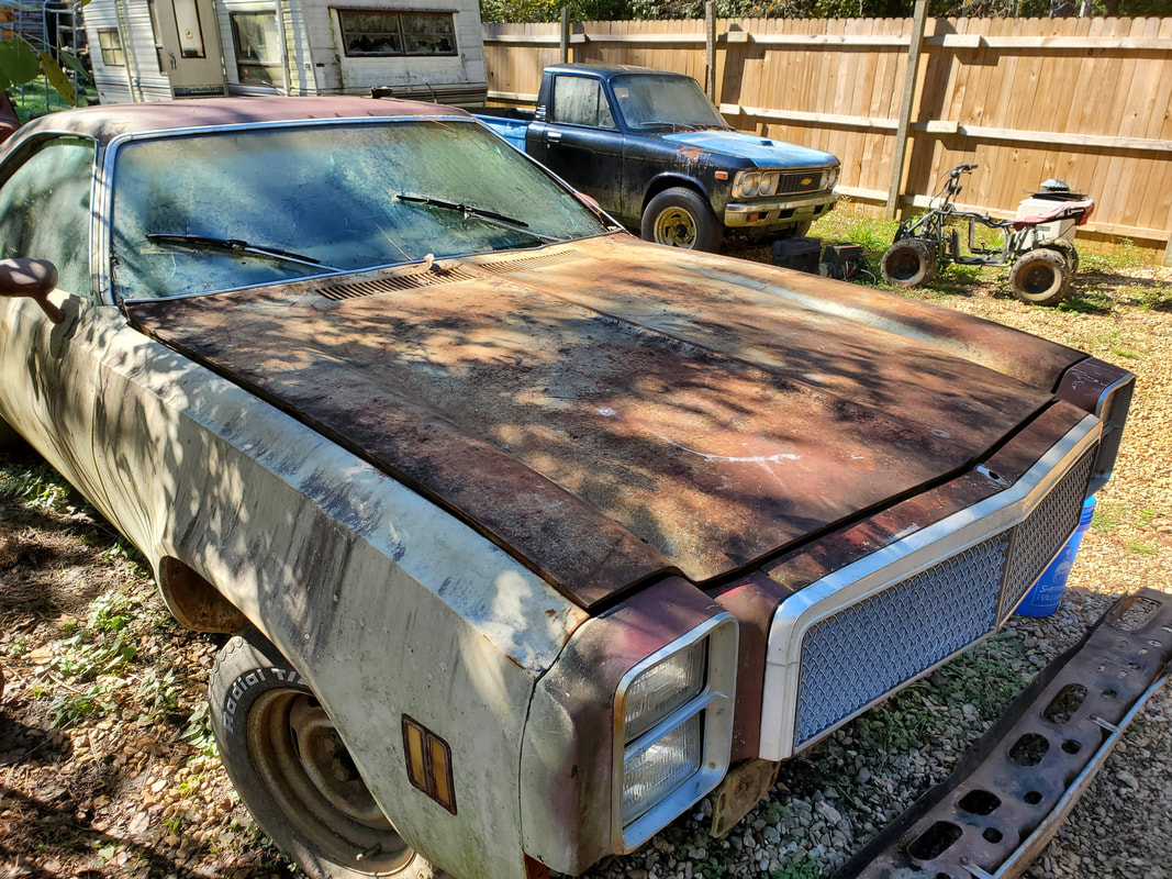
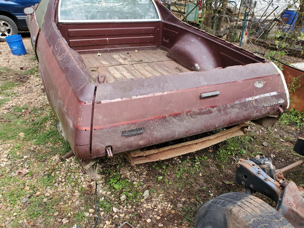
The El Camino as it stands since I last worked on it a few years back. We moved the car from along the main driveway into the newly fenced in compound where I can work on it better on the gravel.
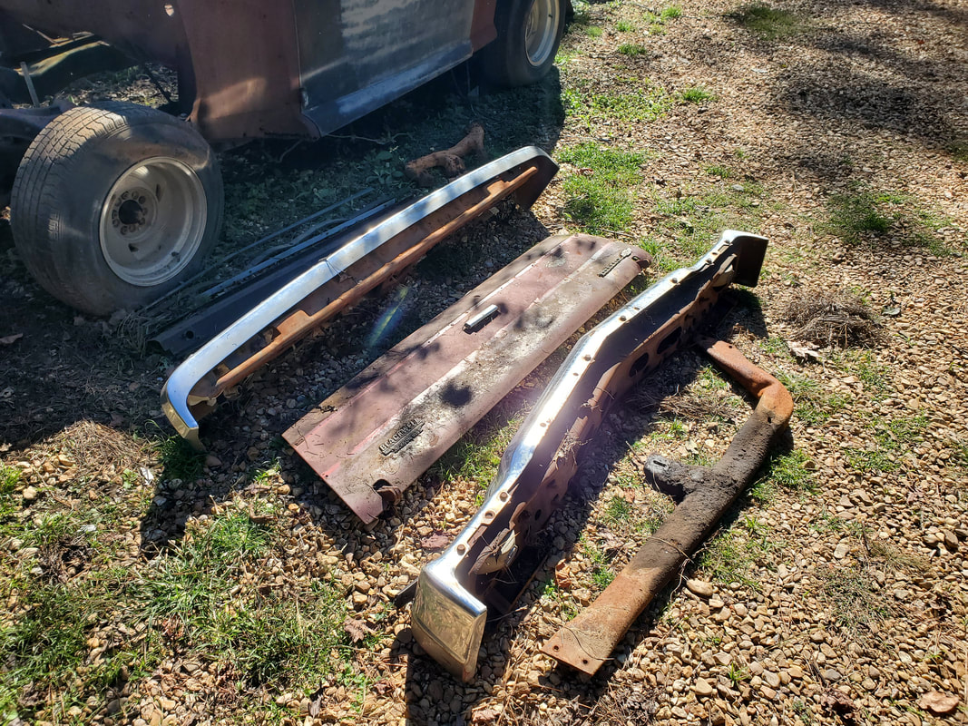
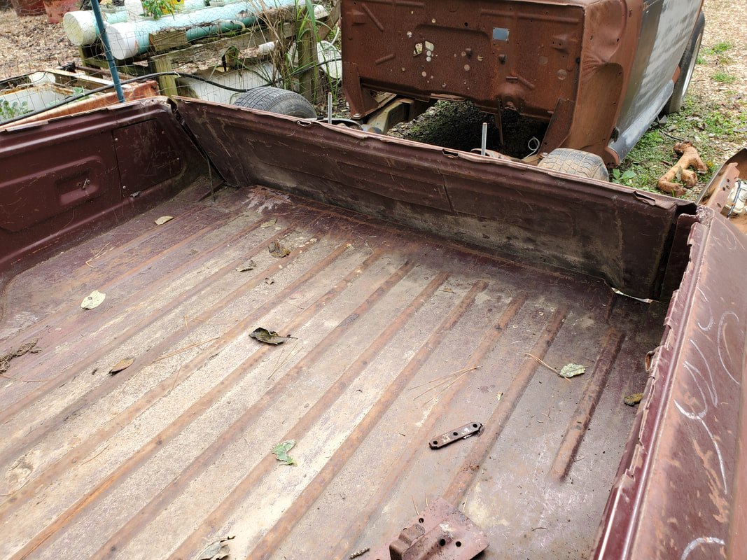
The bumpers, tailgate and transmission crossmember removed from the bed in order to clean the bed of pine mulch and other trash, prior to starting work on the car once again.
Elco bed after clearing larger body parts and cleaning pine mulch from inside the bed.
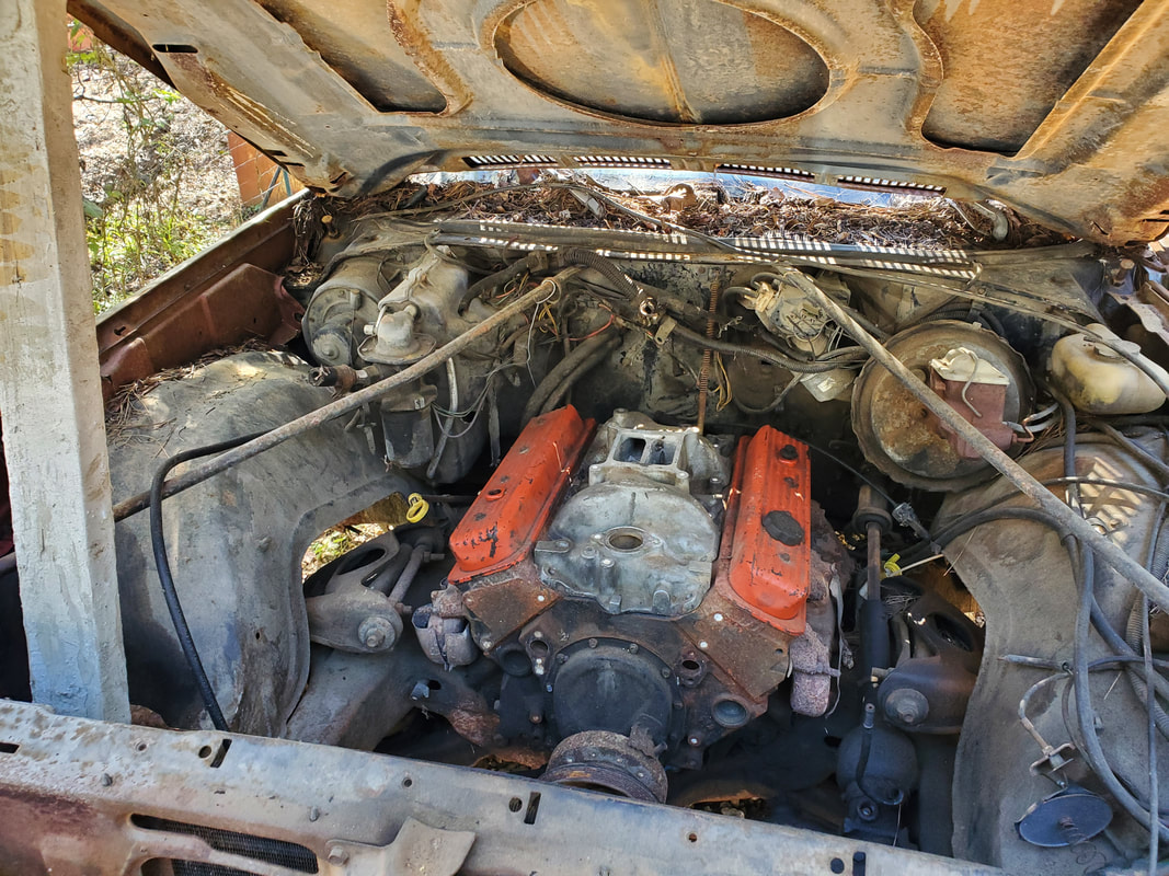
Luckily I didn't bolt down this 4bbl intake on the engine after removing the TBI intake. Rats decided to use the intake as a toilet, causing me to have to vacuum loose rat shit up, then remove the intake and shake out the bulk turds.
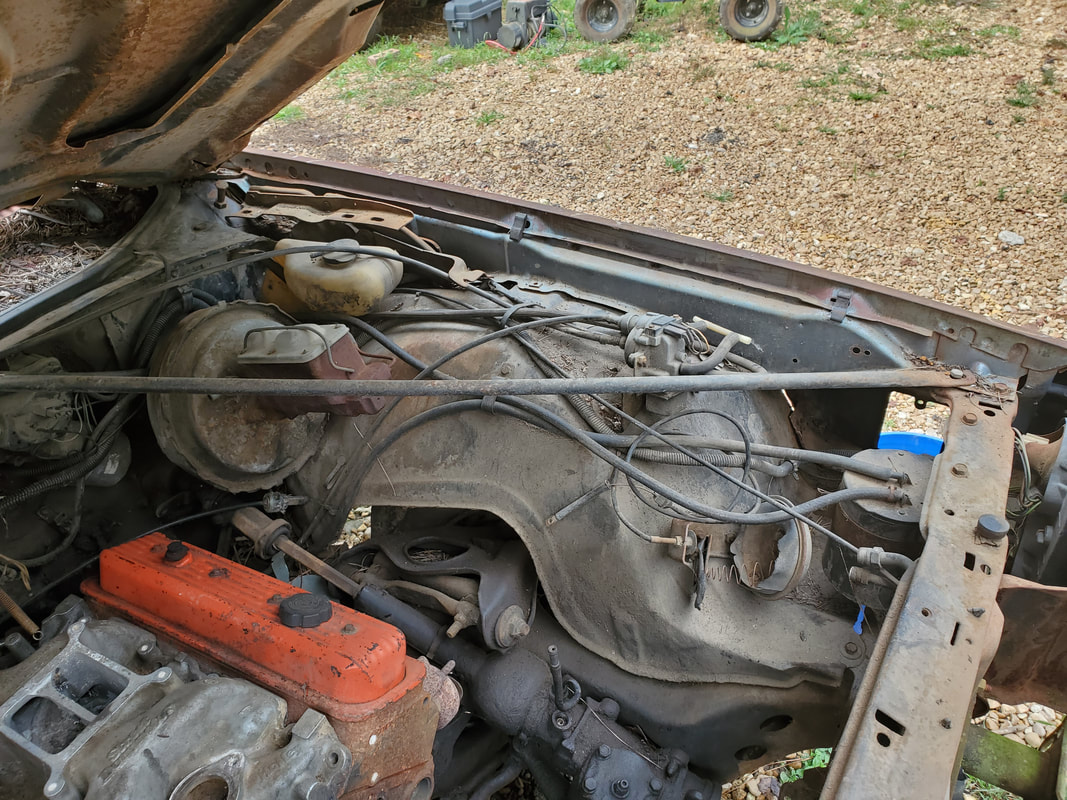
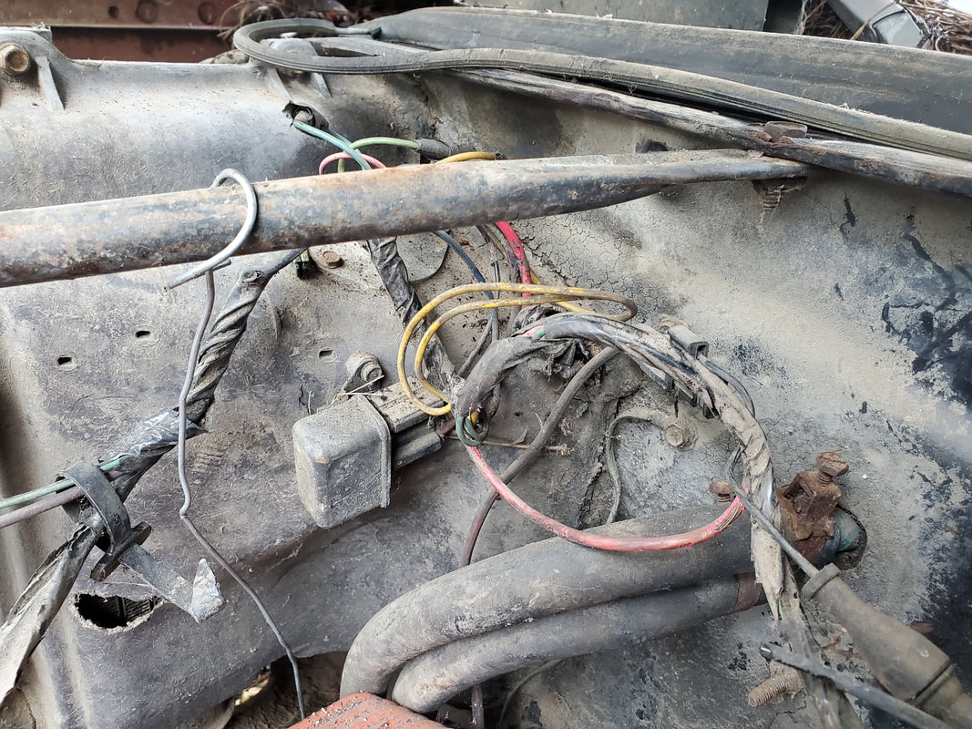
Emissions related hardware as well as a cruise control module that will all be removed during the work on the car. I will research the cruise control to see what all it may need to actually reuse this feature on the car. It would be kind of cool to have cruise control on this "old" car.
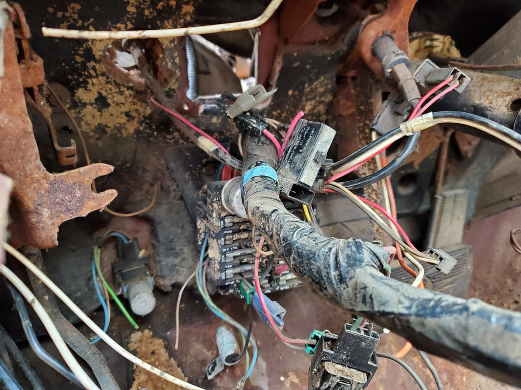
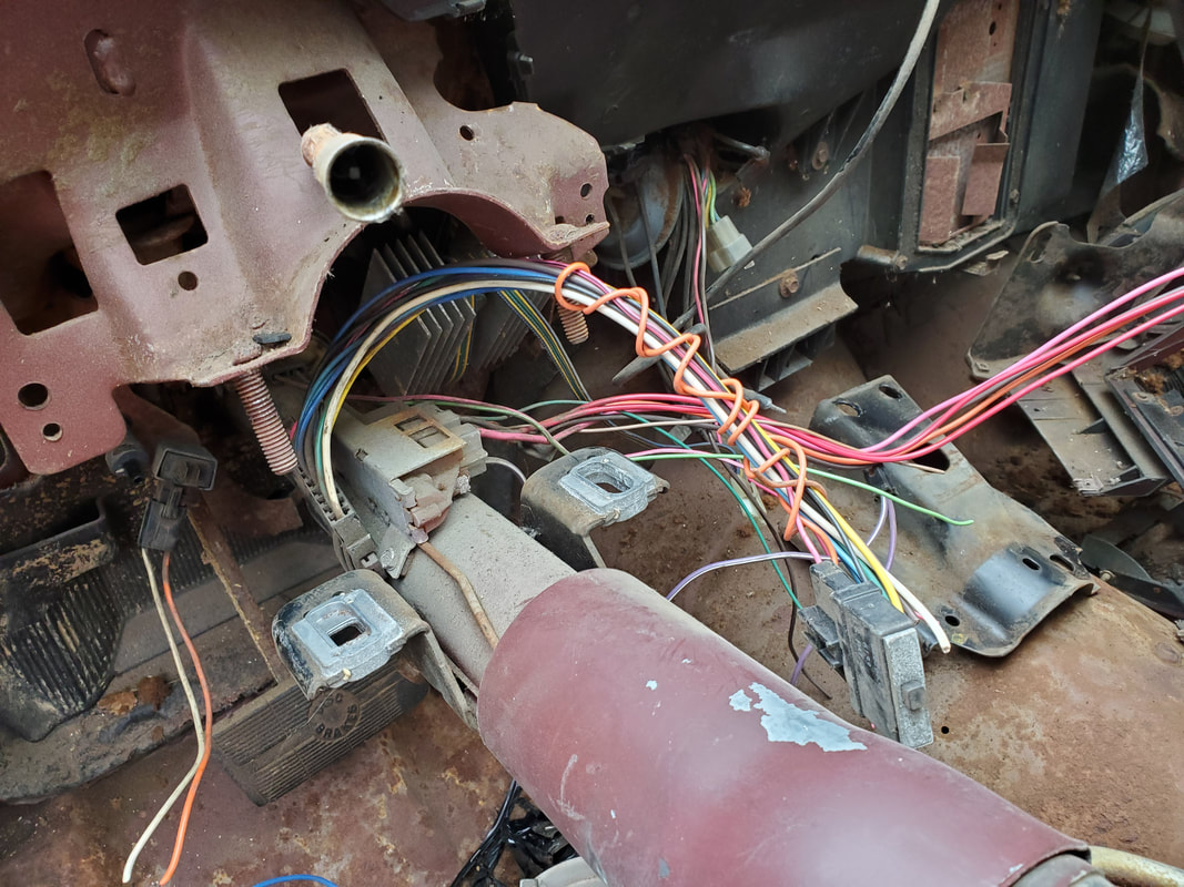
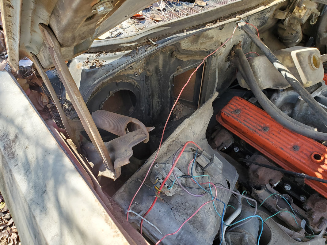
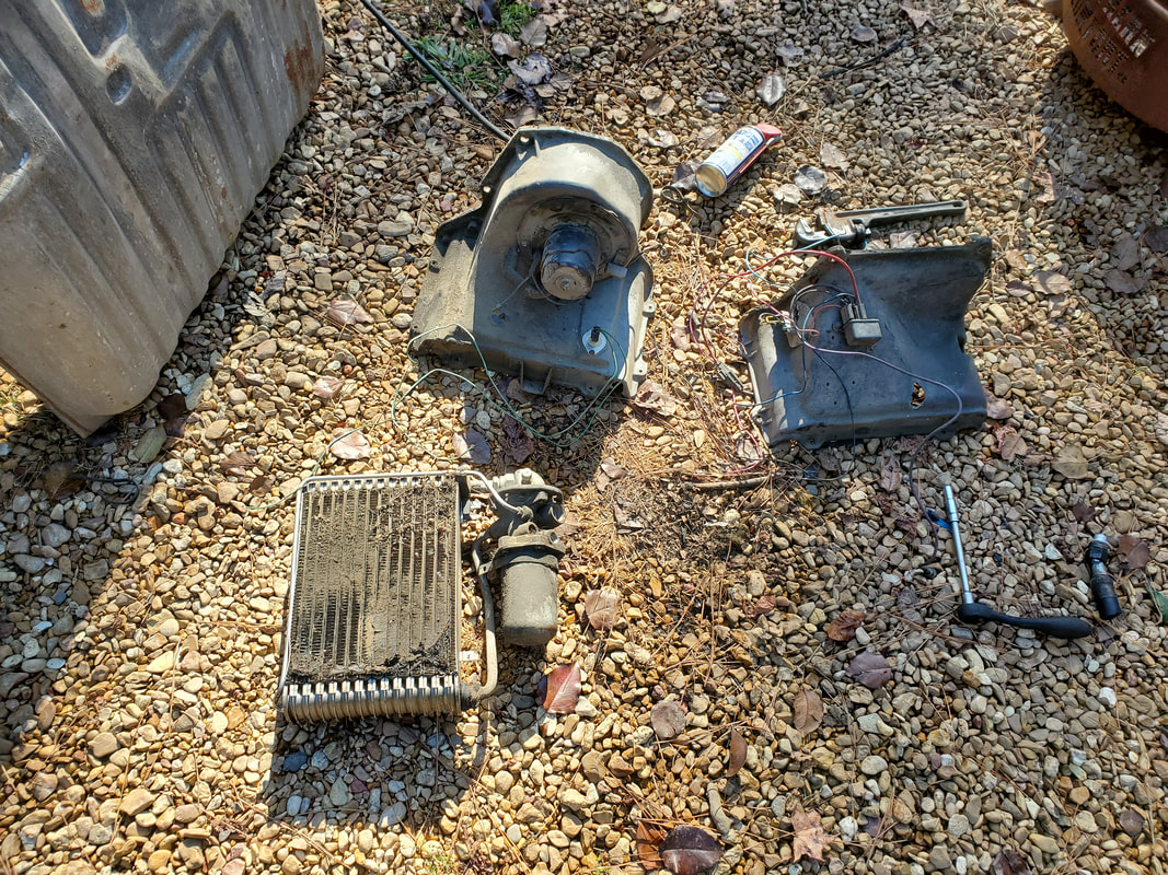
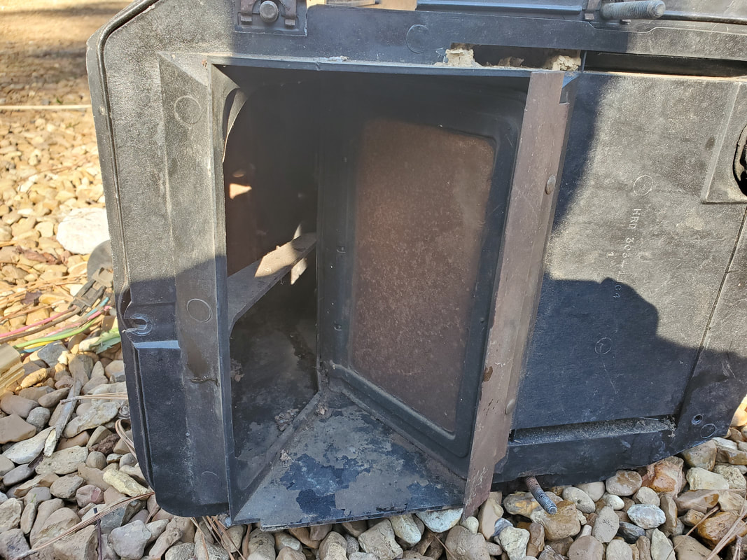
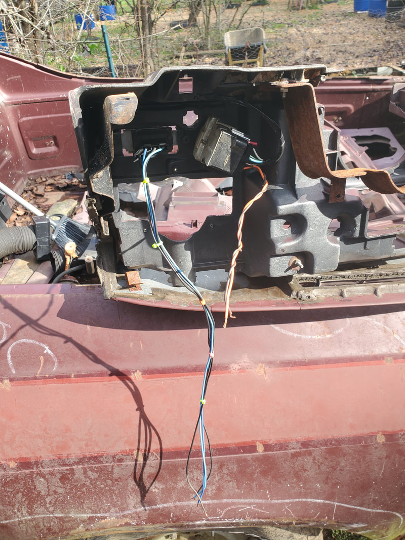
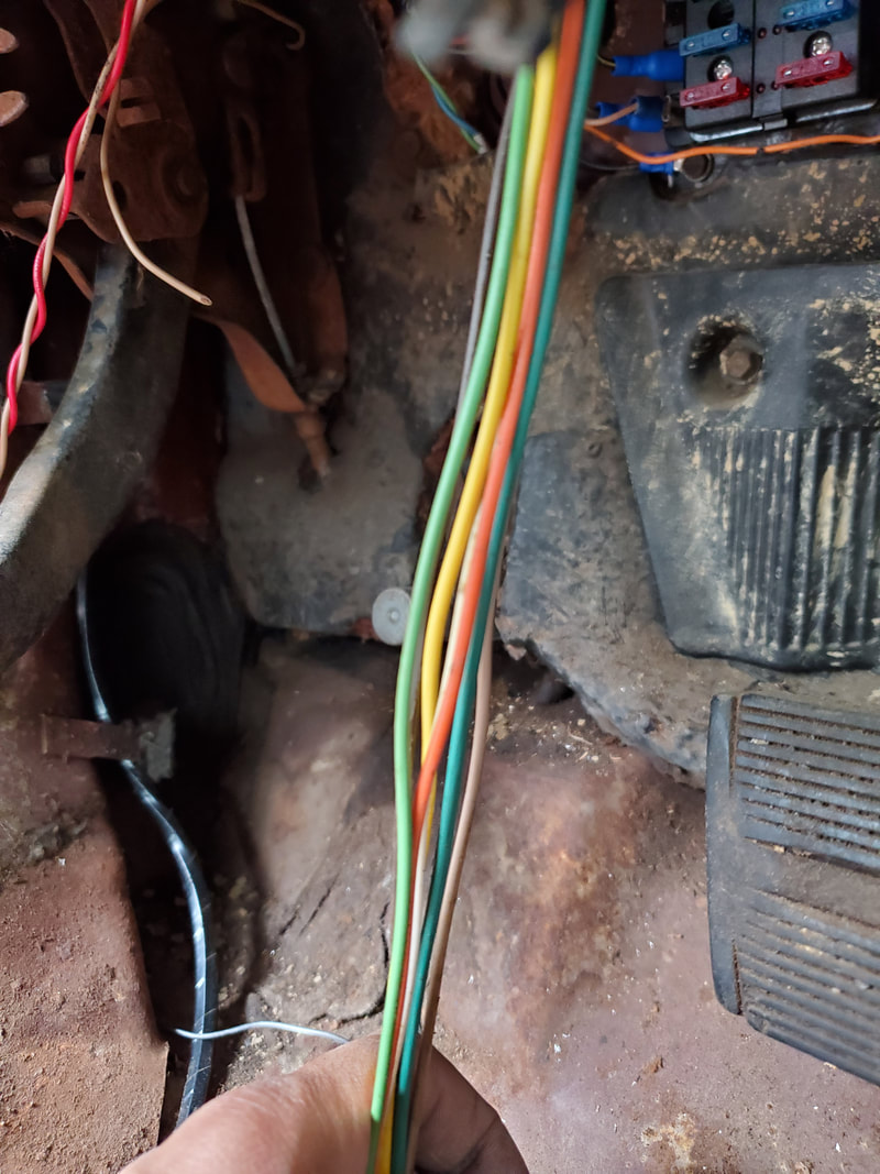
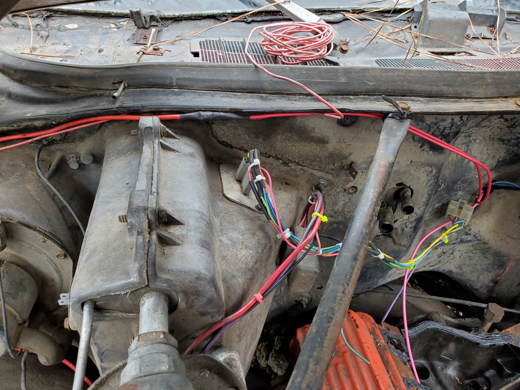
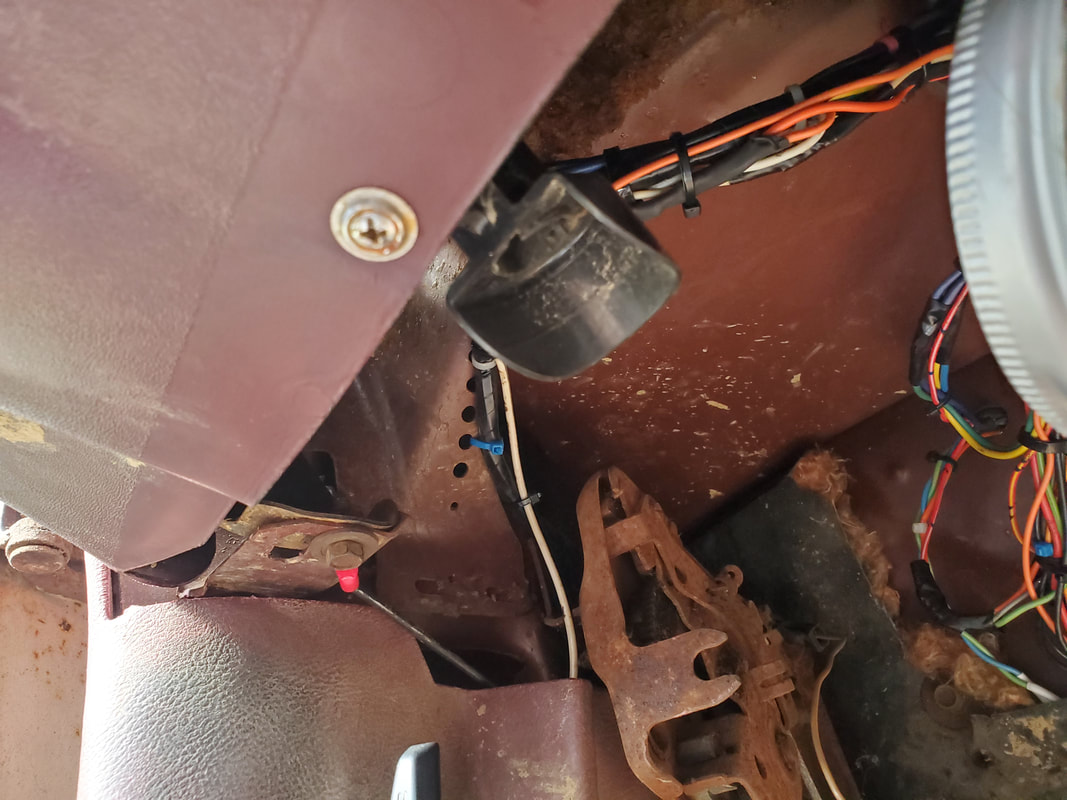
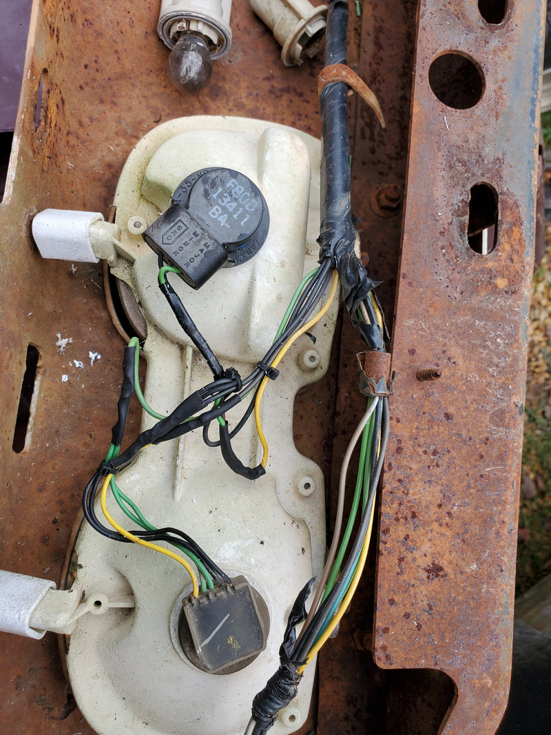
Firewall and HVAC box where wires and other hardware are situated. When I rewire this car I'll be cutting most of these wires in order to connect them to the new wiring that will be run through the car.
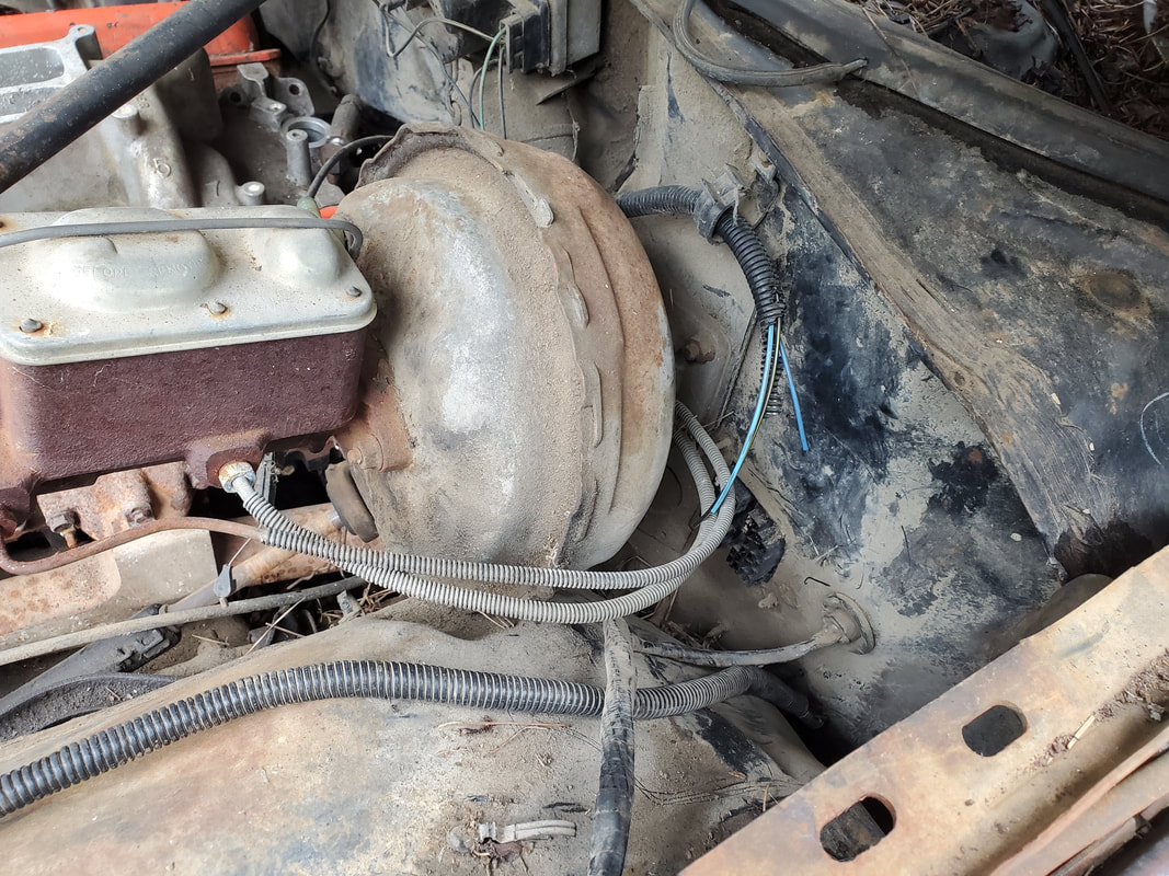
One of the first things to be removed from the car was the old AC condenser. This part was bent up some and more than likely wouldn't hold refrigerant if I did reuse it.
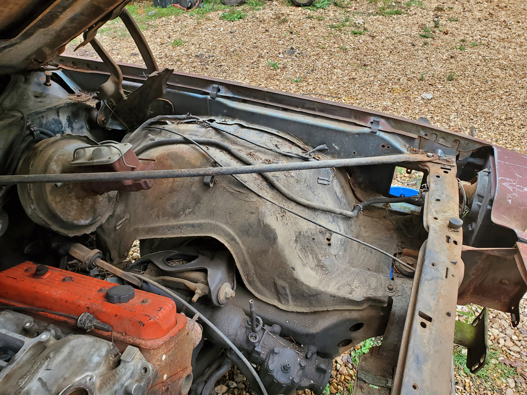
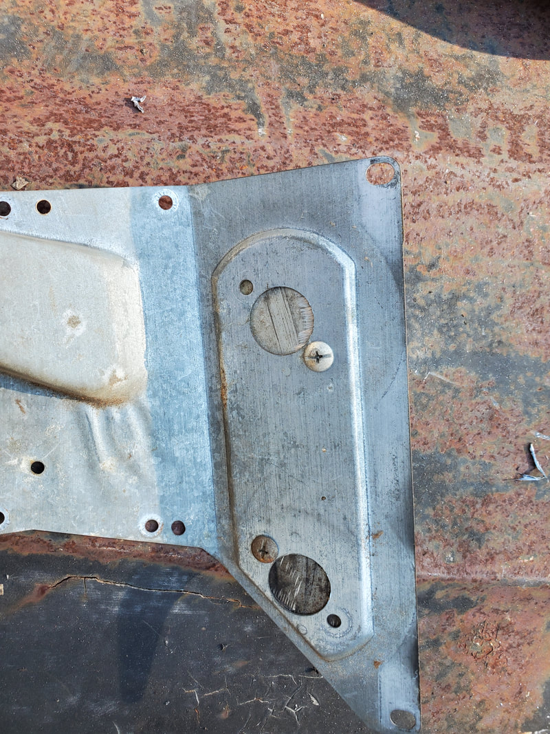
Left fender well after removing old charcoal canister, cruise control and other hardware that isn't needed.
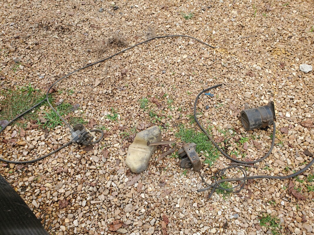
Hardware removed from left fender well.
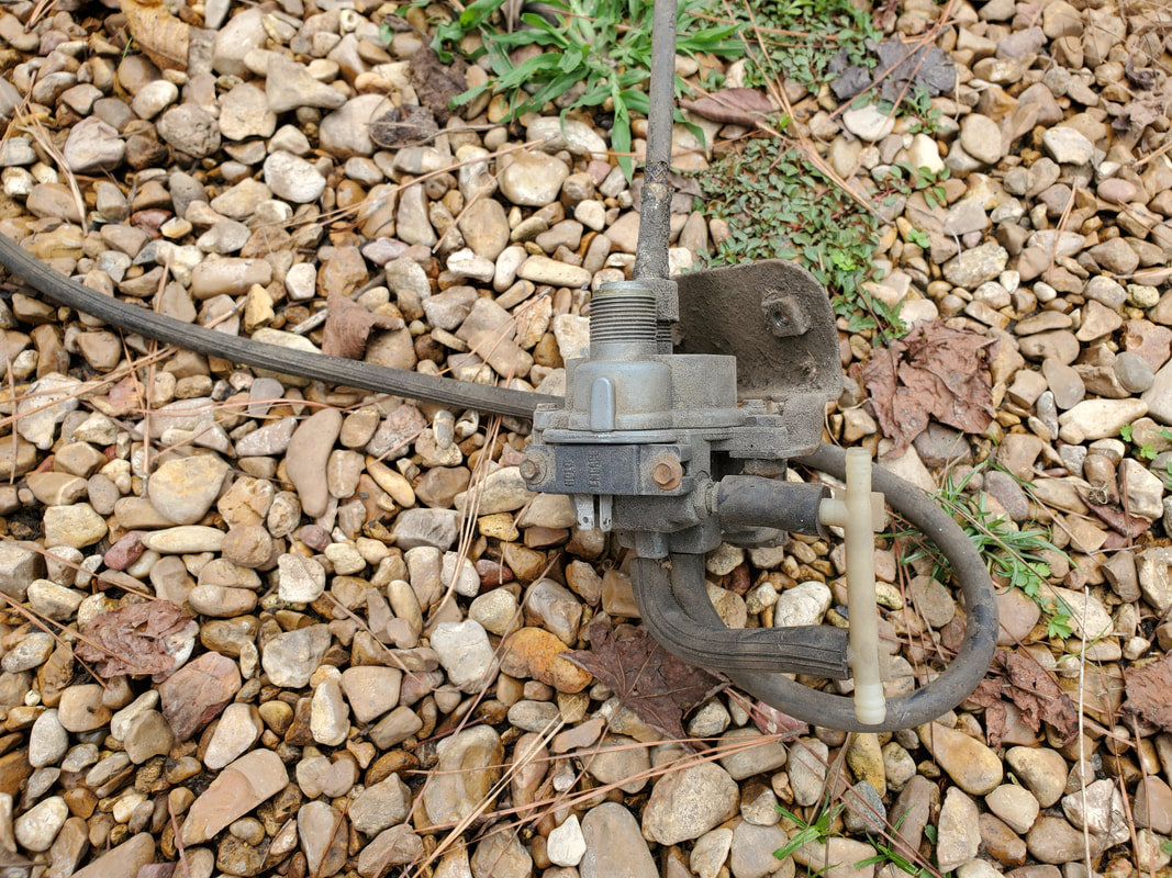
Cruise control module removed from car, I really want to try and reuse this. Its really a simple setup that helps in holding the throttle to maintain a set speed, its a simple electro-pneumatic actuated module.
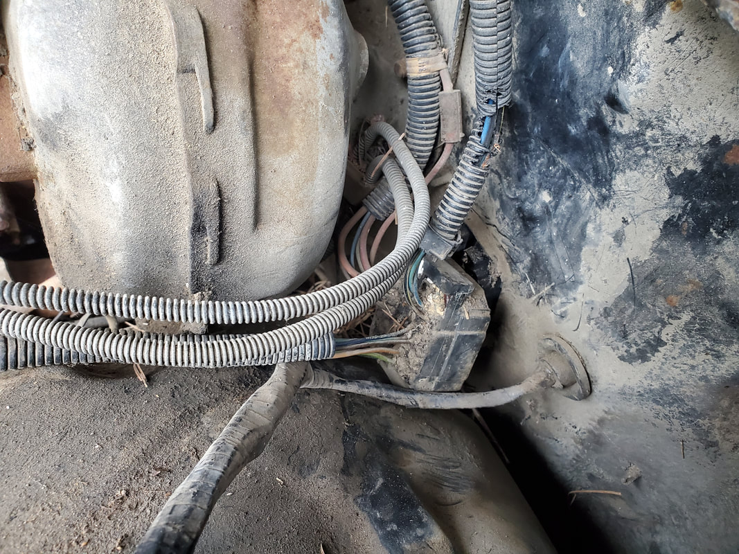
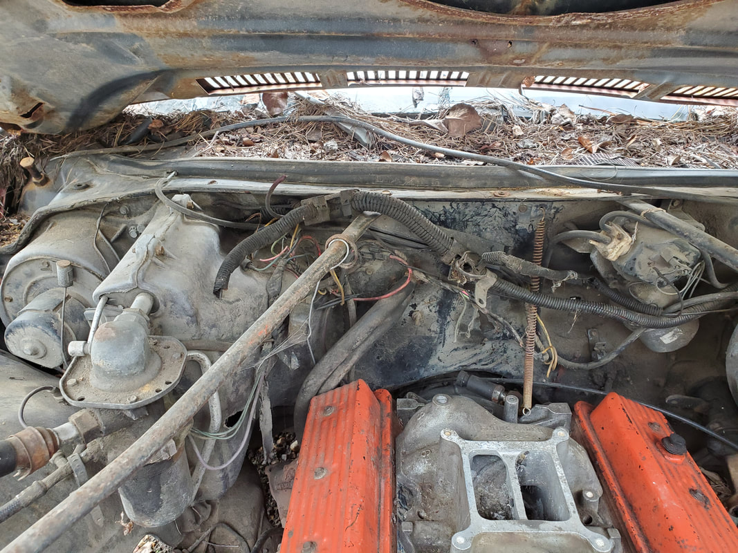
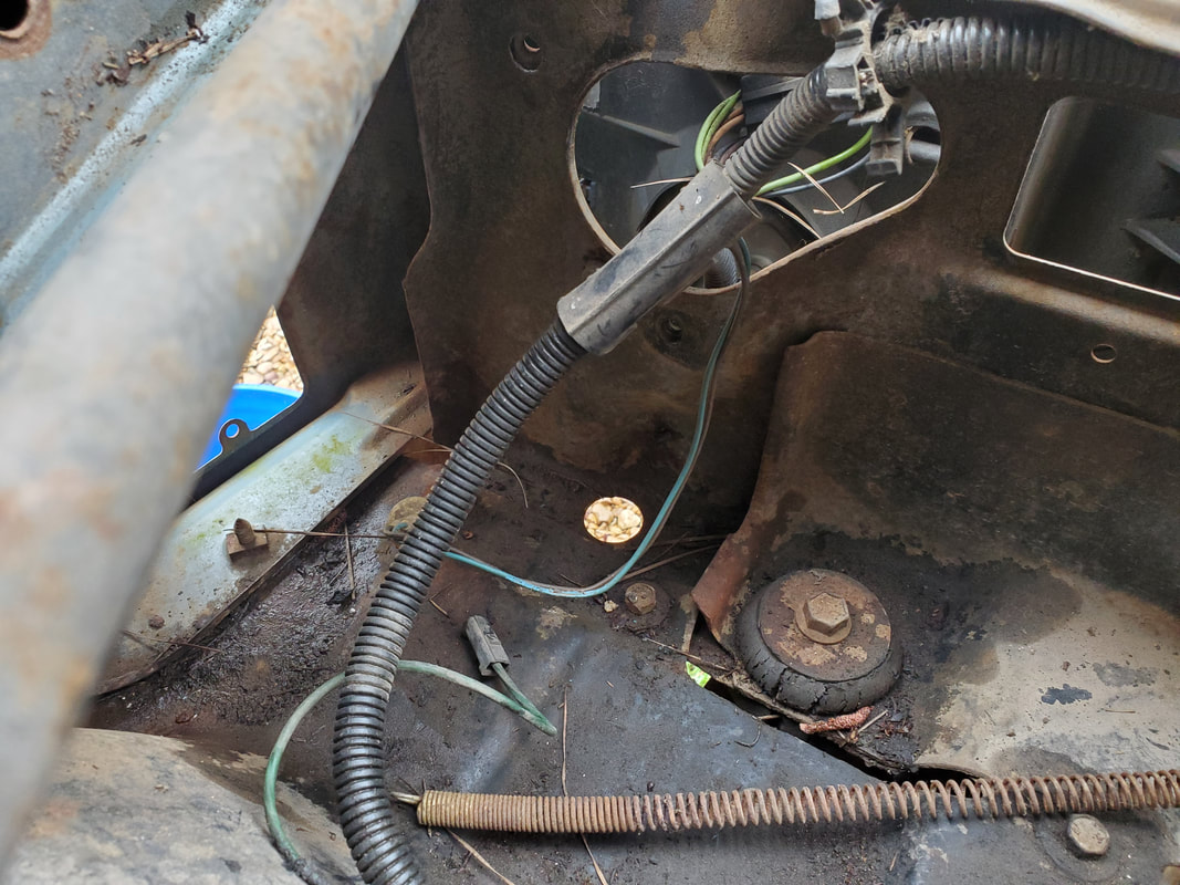
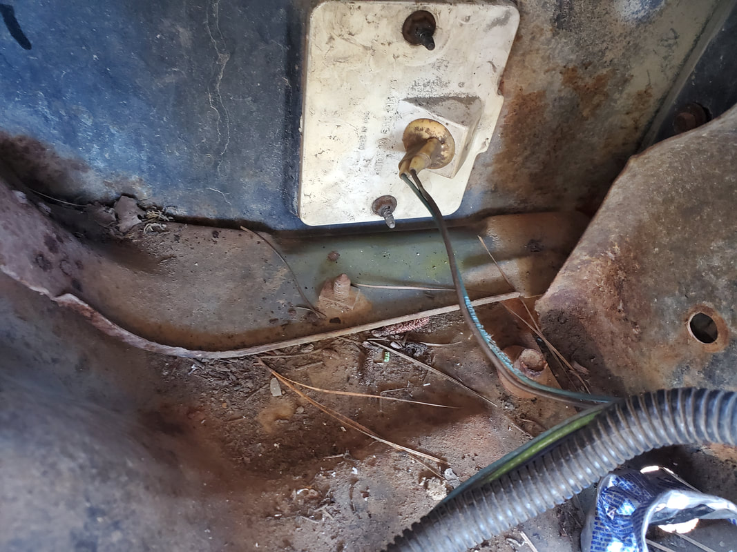
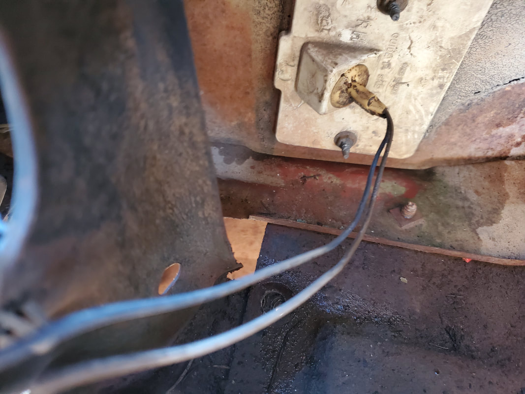
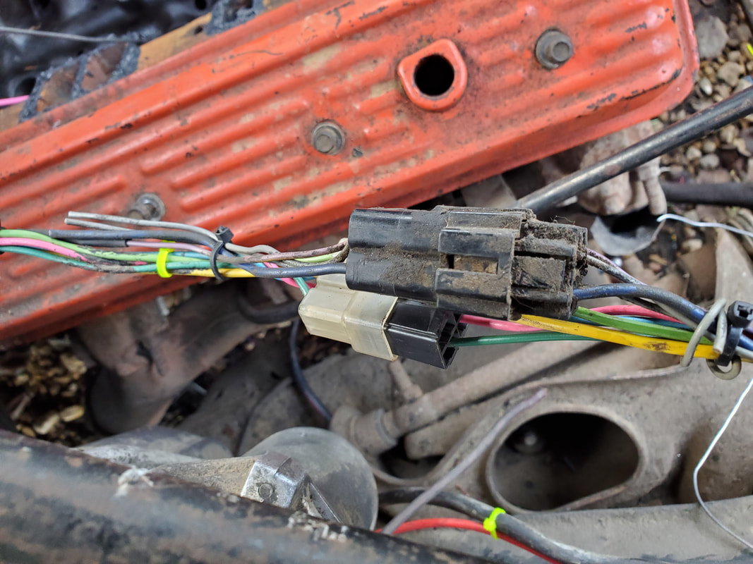
Junction plug where engine bay wire harness plugs up. The engine wire harness will be removed and the plugs for the different devices will be cut from the harness, leaving several inches of wire to connect to the new wiring when I do run the circuits.
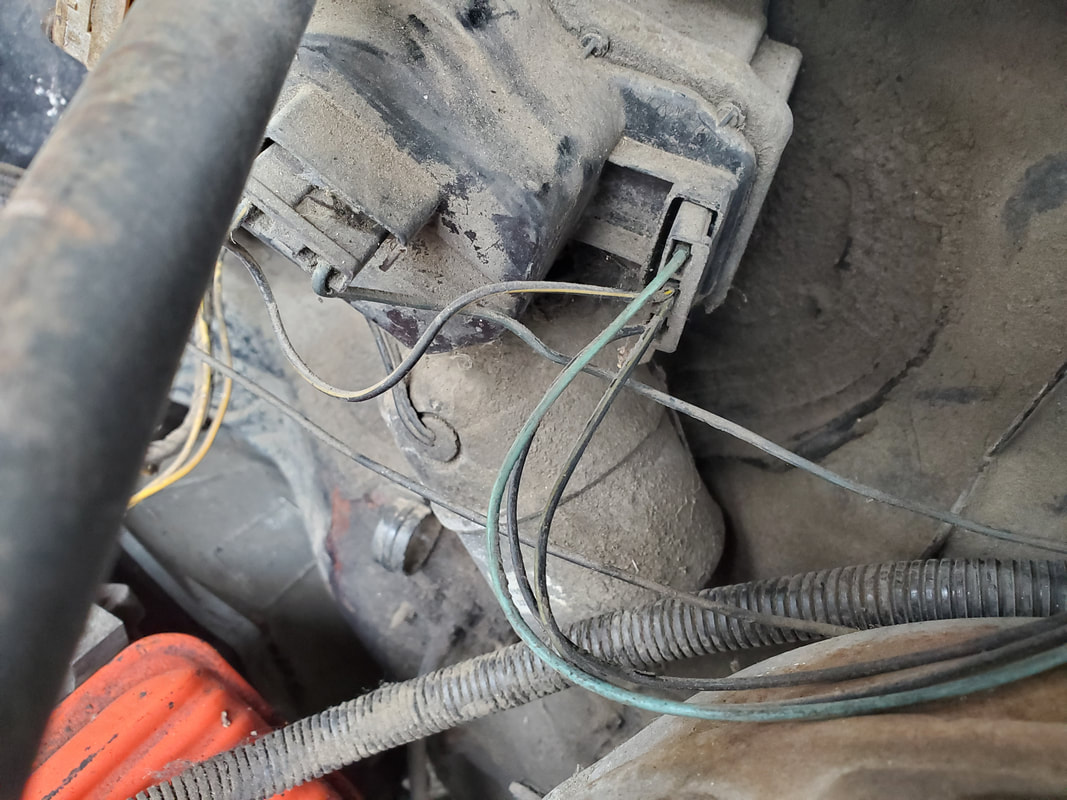
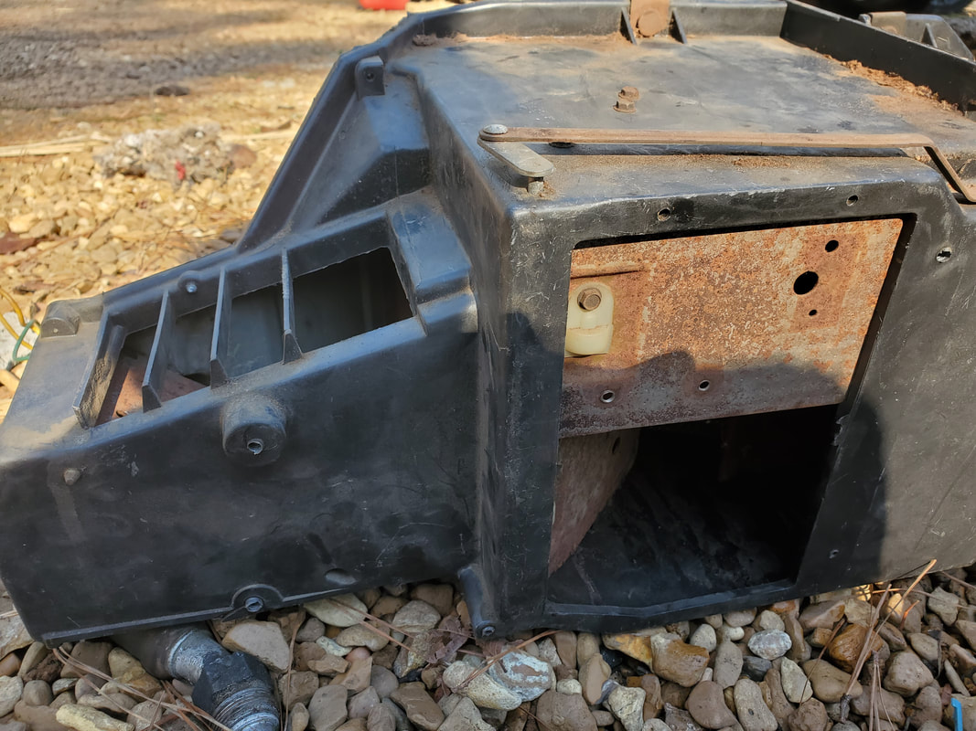
HVAC box and wiring going to blower motor and other associated HVAC hardware. This box, if reused, will have to be patched due to the obvious hole chewed in the side of the box. Otherwise I'll have to replace all of this with a simpler HVAC system that takes up less space under the hood, we'll see.
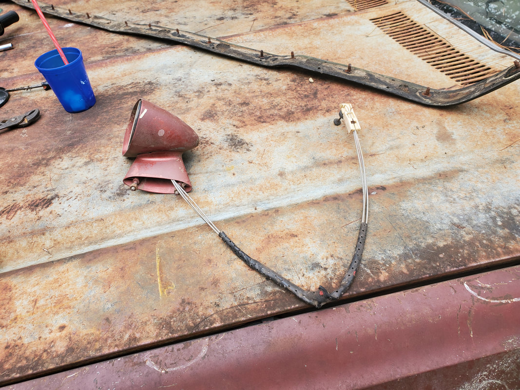
Length of wiring cut from bundle feeding headlights and front side marker lights. I'll hook into this with the new wiring when I get to that point in the project.
Wiper motor plug with short run of wires after cutting harness.
Engine control wiring which will be completely removed as there are no usable plugs on these wires.
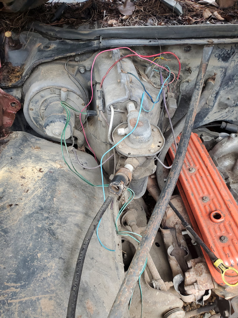
Wires going to plugs on HVAC devices after cutting the wiring harness out of the car.
Junction plug with engine harness removed fully. Note the wires over the brake booster, these are for the wiper motor. The flexible shielding is for the headlight wiring that I cut close to the firewall since this wiring is still intact.
After removing the hardware and wiring that I planned on removing I got to work on putting things back together. It appears the previous owners disassembled this car with the hope of restoring the car then reassembling the car with these same components or better looking replacements. Most of these parts - moldings, panels, fixtures, etc, are mostly intact and able to be reused so I'm going to just commence putting this car back together so I can get to the point where there's no left over panels or other components, allowing me to focus more fully on the electrical and mechanical aspects of this car.
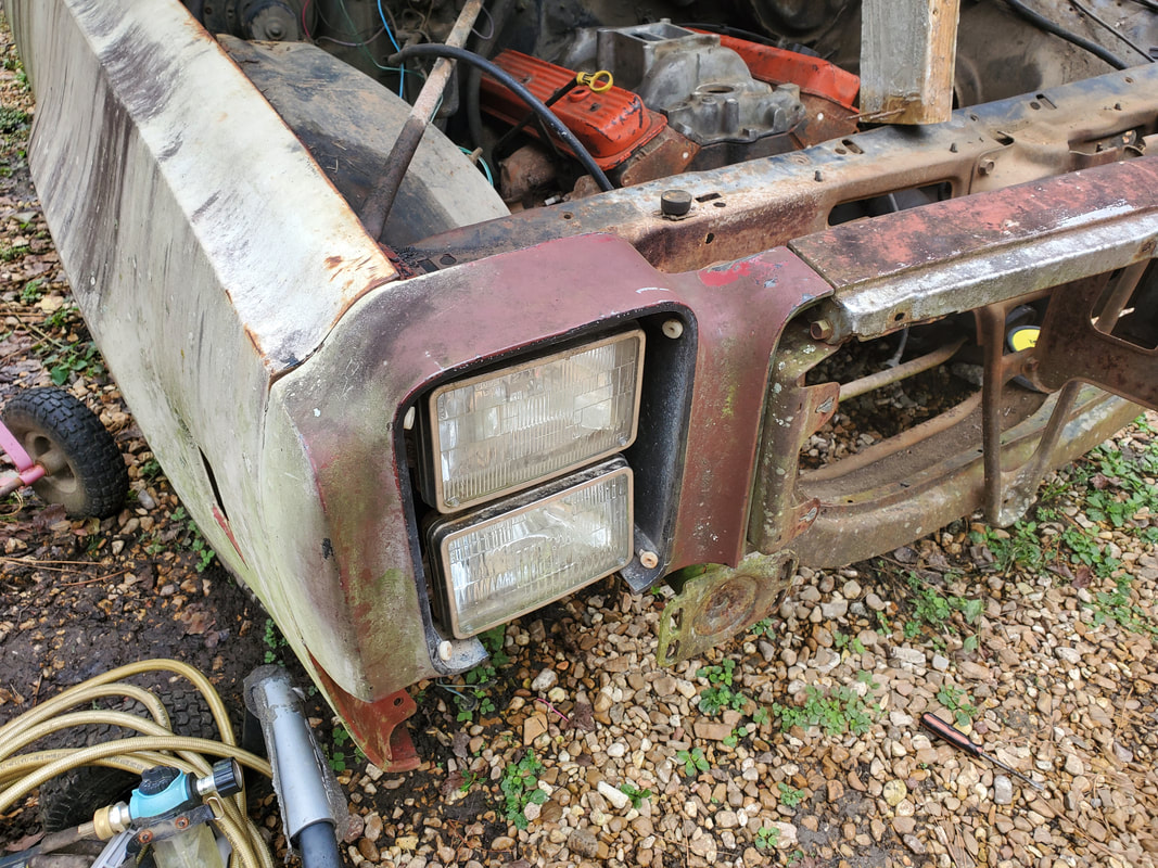
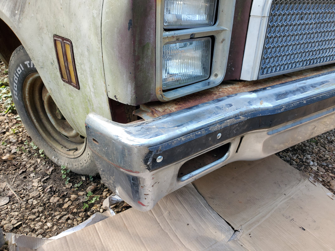
Right headlight housing needed to be remounted as there were several bolts missing. After replacing these missing bolts I got the housing secured properly along with the right side of the top body/grille trim panel.
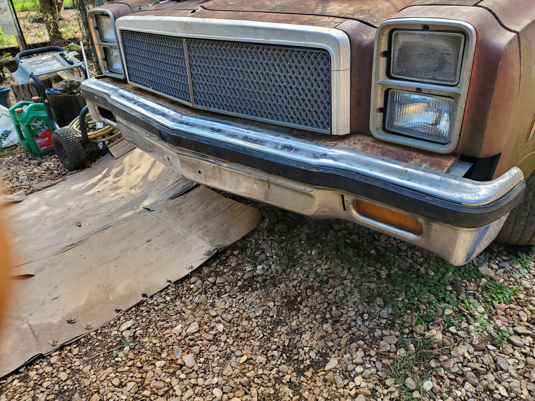
In the process of installing body parts, I got to the front bumper. The bumper is held on by two brackets that have four studs each and are held in place on the inner bumper by lock washers. This allows the brackets to stay in place while the bumper is hung against two posts with four holes to accommodate the studs, then secured with nuts. The bumper itself is two parts, the inner bumper that holds those mentioned brackets and the outer bumper which holds the turn signal light fixtures and is the more aesthetically pleasing part of the bumper assembly. After trying to install the bumper it turned out the inner bumper was bent where the brackets mount due to a front end collision. I had to disassemble the bumper in order to be able to beat the inner bumper straight again. That was fun...
Back of inner bumper showing the dented in section right of the signal light. The holes are where the studs from the bracket would poke out from. The bracket would be placed inside the bumper.
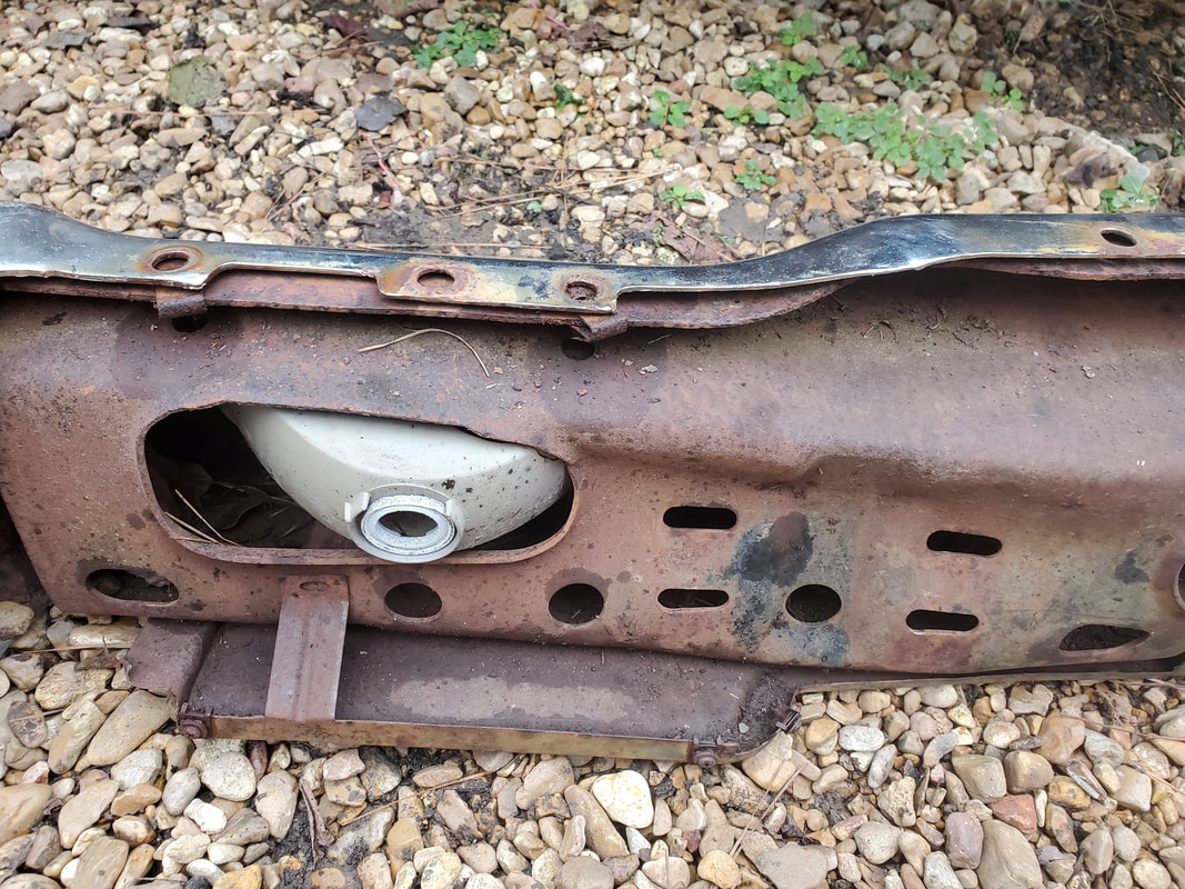
Right side bumper mount, note how the bottom of the mount is bent, damage from the same accident that bent the inside of the inner bumper. These mounts are not able to be straightened out due to their position where a sledgehammer can't reach it and the studded mount inside the frame is frozen at the nut or whatever it is that is holding the mount in place. This shit is not coming out easily.
The left bumper mount's damage is even more pronounced than the right side.
Bumper after removing rubber strip that covers carriage bolts that help secure outer bumper to inner bumper. A line of regular bolts also hold the two pieces together. The hex bolts were able to be removed easily but the carriage bolts had to be cut off due to being rusted to their holding nuts.
Rubber strip removed from bumper. This piece has a series of studs that are anchored in the rubber and are held in place with cap nuts.
Since I needed to get some new carriage bolts for the bumper and clean up the threads on the studs of the bumper brackets I turned my attention to installing the moldings, trim pieces and other loose hardware on the outside of the car. This all consisted of grille, grille moldings, door frame moldings, mirrors, door jamb panels and side marker lights. Installing all of this stuff removed this loose stuff from the cab of the car and put it back where it belongs, on the car itself. If I ever do decide to do extensive body work to an extreme level then I would have to remove most of this stuff again in order to be able to prep the surfaces under where these pieces go so I could paint all the metal surfaces properly. Otherwise I would just have to mask off a lot of stuff to not get paint on them.
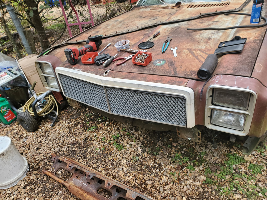
Grille, grille trim moldings and headlight trim pieces all installed. Headlight trim and grille were held in with sheet metal screws to clip pieces in the metal tabs of the body while the grille trim was held in with cap nuts to the integrated studs on the trim.
Driver's side mirror showing remote cable control and knob. Mirror had to be screwed to the base mount before mounting the whole thing to the door using nuts to secure the two studs on the bottom of the base to the inside of the door. The control cable had to be routed through the door and around to a point where it'll be able to be inserted into the door panel when that part gets installed on the door.
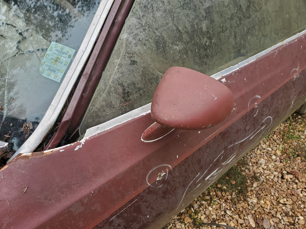
Driver's side mirror bolted to the door.
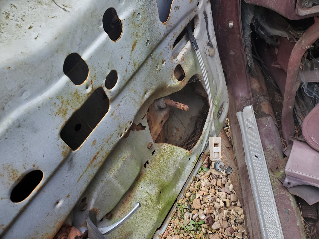
Remote cable control and knob as shown after being routed through the door.
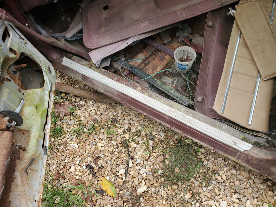
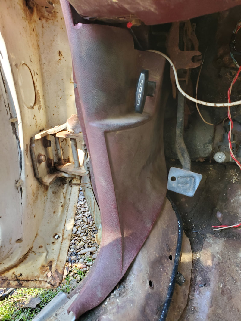
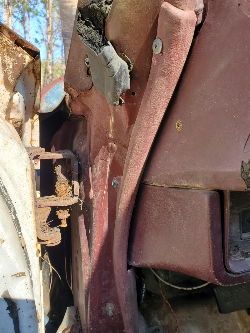
Door jamb trim panel piece secured to the top of the rocker panel via sheet metal screws.
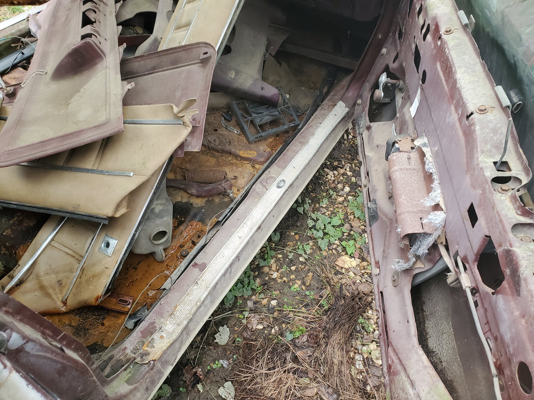
Passenger side door jamb trim panel piece secured to the top of the rocker panel.
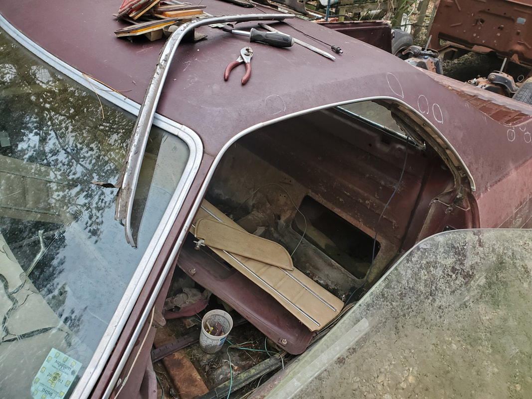
Driver's side door frame trim moldings secured in place via sheet metal screws. Weather stripping used to be under these trim pieces to help cushion the window when the door is shut but are long gone. I'll have to remove the trim pieces to install new weather stripping.
Passenger side door frame trim molding installed the same as the driver's side.
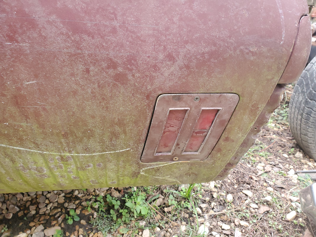
Driver's side rear marker light installed. These are installed from the outside and are held in place via two sheet metal screws.
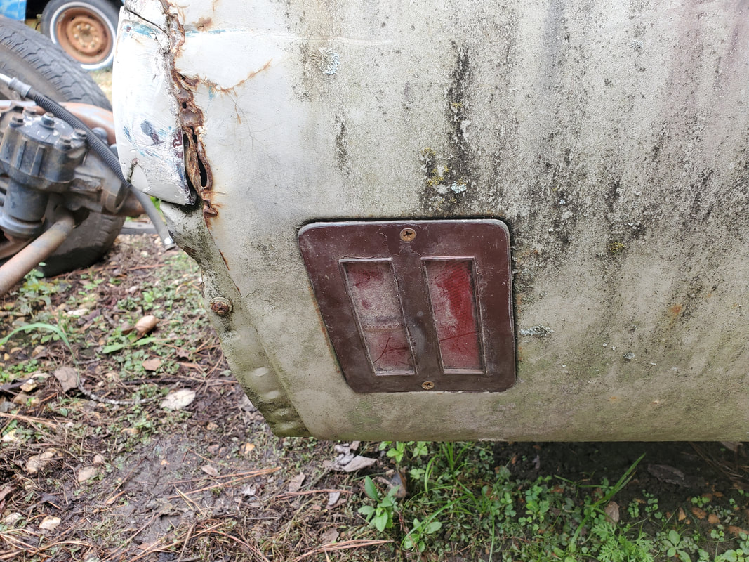
Passenger side rear marker light installed.
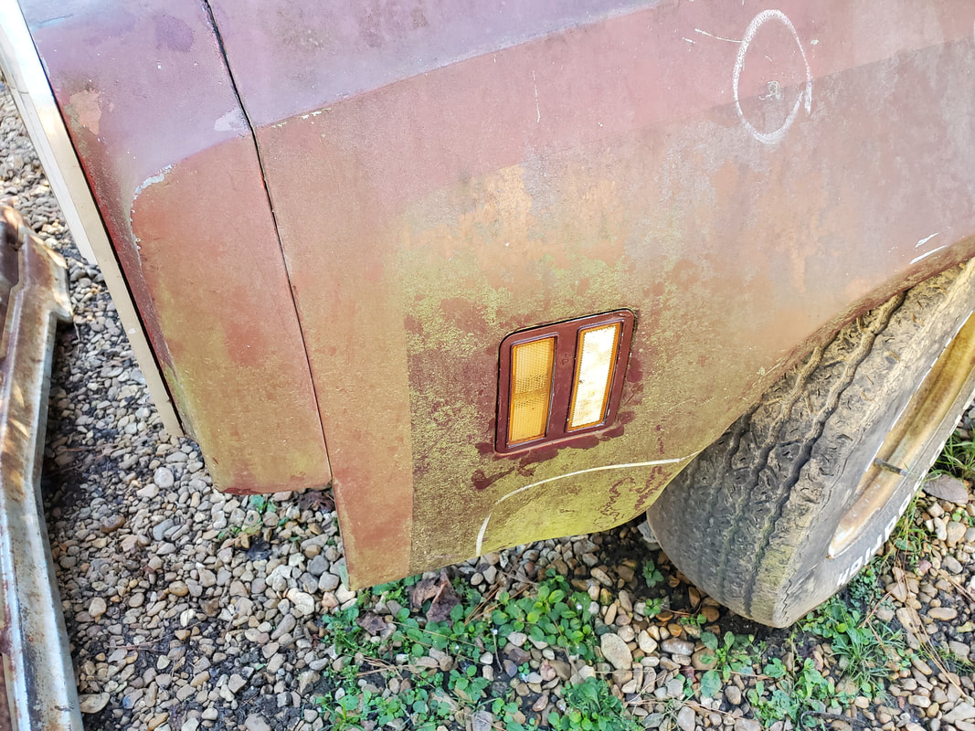
Front left side marker light fixture installed. These fixtures are installed in two parts, the inner shell that holds the light socket is installed from the inside while the lens frame piece is installed from the outside. The lens frame has two studs that pass through tabs on the fender and through the inner shell and are held in place with cap nuts.
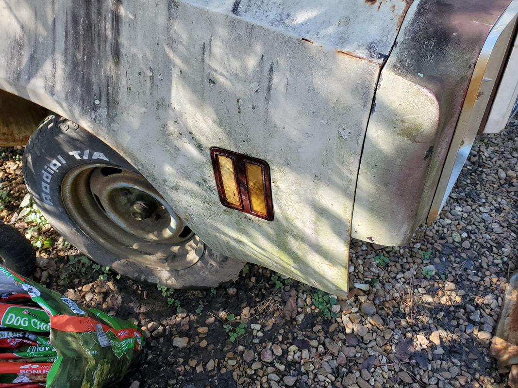
Right front side marker light fixture installed.
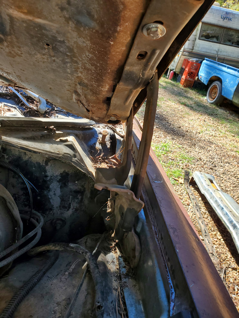
With all of these trim pieces and other hardware installed I then turned my attention to the hood. I happened to have the other hinge sitting loose in the cab with the rest of the hardware, along with the springs that go on both hinges to hold them in the open position under the weight of the hood. I had to use a grade 8 bolt to cut the threads on the hood so I could install the shorter bolts I planned on using, without the risk of stripping the threads or breaking a bolt off in one of the holes. After installing the hinges I put the springs on then got the help from the ole lady to hold the hood while I installed the bolts to hold the hood on. I then discovered the driver's side hinge was flexing sideways when I tried to close the hood so to keep the hinge from just fully folding up to the point of being useless, I removed the spring. While I can close the hood I'll still have to use a board or pipe to hold the hood open. It's a small price to pay for not having to immediately hunt down replacement hood hinges. Also I had to cut a longer bolt slot on the passenger side hood hinge to allow me to slide the hood back some more to allow it to close properly without laying on top of the fender or anything. Using the die grinder I cut into the hinge by the holes to make them longer. The job wasn't clean but it had to be done in order for me to close the hood properly.
Hood after bolting to hinges that were also bolted up to side firewalls in engine bay.
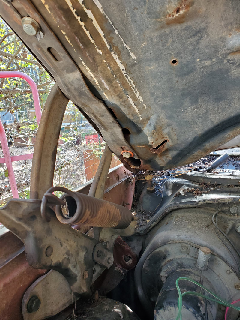
Passenger side hood hinge bolted to side firewall. Note spring hooked to top of hinge. This stretches under pressure from the closing hood only to spring back out when opening the hood to help hold the hood up.
Driver's side hood hinge in place bolted to hood. Note absence of spring on this hinge.
Hood closing properly after slotting the bolt holes even more than they already were. I have to get a fresh pair of hood hinges with the springs so I can at least be comfortable in knowing I have good hinges hooked up to allow me to close the hood right. I'll have to address whether I have to straighten out the front body panel and/or headlight frame body pieces to allow the hood to close due to same accident damage that killed the front bumper.
The next thing is the front bumper. In order to do this I had to do a couple of things first. First I had to take the bumper mounting stud brackets and cut the threads to clean them from the surface rust that built up on them. This was done with a simple die. I also had to straighten out the bracket so the studs were straight enough to pass into the bumper mounts on the front of the frame of the car, but before straightening the studs out I cut the threads since the die tool wouldn't pass between the studs if they were straight. After cutting the threads on all the studs I then had to straighten out the bent up surfaces of the inner bumper. This was easy to do since I separated the bumper assembly into their separate pieces. I beat the shit out of the inner bumper with a sledgehammer to straighten the surfaces out as much as possible. Afterward I took one bracket and tack welded the piece to the right side of the inner bumper. From there I was able to hang the inner bumper in place on its mount, using some washers to help level the inner bumper due to the frame mounts being distorted. I was able to install the other bracket and get both secured with the washers and nuts I had available, all but one stud. After getting the inner bumper mounted I was able to slide the outer bumper over the inner and install the carriage bolts I had, getting them secured then moving on to the hex bolts along the bottom of the bumper, getting them installed. With that the front bumper is secured and centered and leveled. Other than the rubber strip that goes across the bumper to cover the carriage bolts across the front of the bumper, we can move on to something else on the car.
Right side bracket tack welded to inner bumper to allow for easy installation onto the frame mounts. The bracket is centered to ensure that the inner bumper is centered on the front of the car. Note the crack to the left of the bracket, showing where I beat the surface with the sledgehammer to straighten it out.
Shot under the inner bumper showing the washers that were used to space out one of the studs on the bottom of the right bracket. The washers show just how bent the frame mount was. This spacing allowed for the inner bumper to be leveled properly. Nuts are installed on all but one stud, the one with the washers.
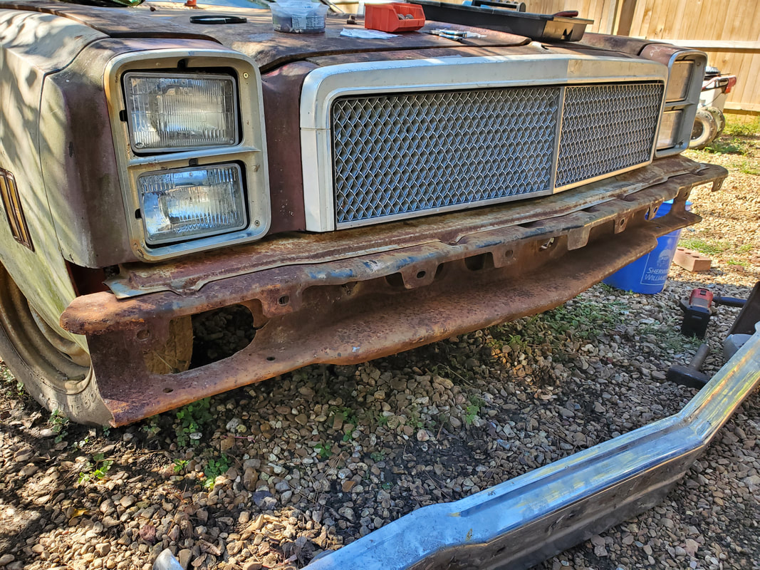
Inner bumper installed on front of car. I didn't need any spacers on the studs on the left side due to the surface of the inner bumper being at the right angle after beating it to allow it to mate against the frame mount and be secured with nuts.
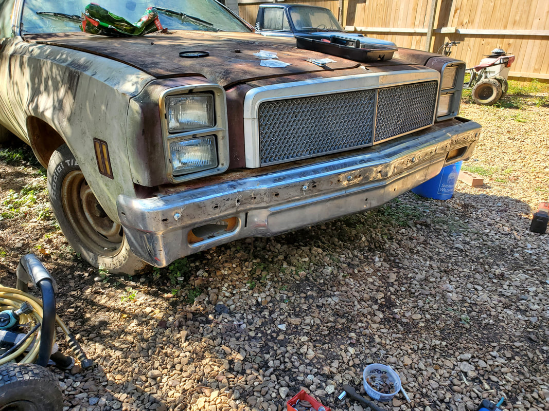
Outer bumper mounted in place. Five carriage bolts were bolted across the front of the outer bumper evenly to hold the front in place. One of the carriage bolt holes on the far left of the car needed its hole reamed out a little due to a slight misalignment. The multiple hex bolts on the bottom of the bumper went in without incident. Other than the rubber strip and replacing the passenger side signal light, the front bumper is done.
Rubber strip secured across front of outer bumper. This strip has a series of studs embedded that are 1/4" thread, normally used with cap nuts but because I didn't have enough available due to using them to secure the grille molding, I used regular nuts to secure the strip on the bumper.
The last foot of rubber strip was missing two studs due to them being pulled out during its removal. I drilled two holes and inserted carriage bolts in the rubber strip to secure the end of the strip. I'll probably paint these bolt heads to mask them easier.
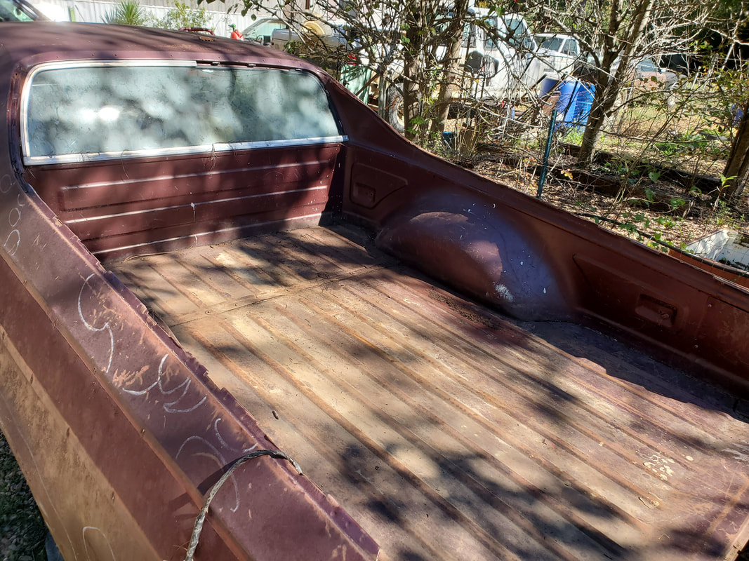
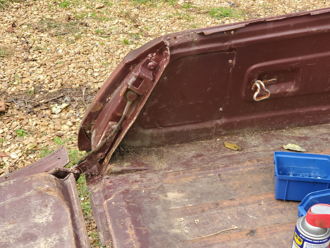
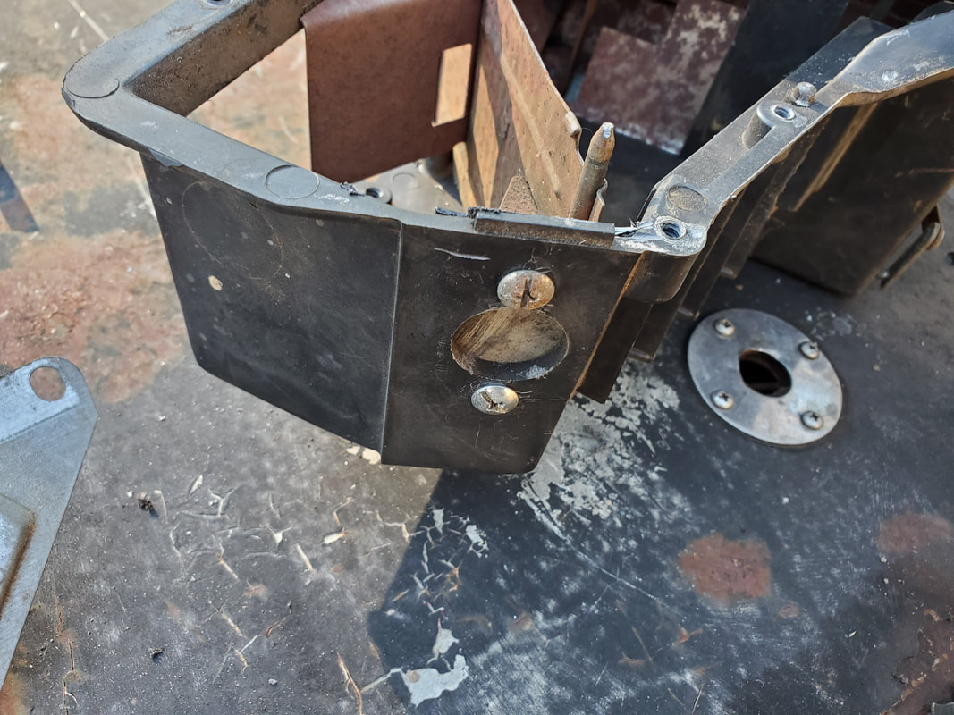
The next thing on the list was the installation of the tailgate. This was pretty easy, just three bolts on each side to secure the hinge to hold the piece in place. There are two thread panels that are stuck inside the fender to take the bolts but the threads are rusted enough that even after trying to cut the threads with a grade 8 bolt I still had resistance. One of the panels popped loose, so I ended up popping the other one loose, choosing to just use regular nuts and washers behind them to secure the hinges. Luckily there are two access panels in front of the hinge mounting points that are each held in with four sheet metal screws. All but one screw on each panel came out easily, but it still allowed me to turn the panels out of the way to allow me to get my hand inside to install the nuts. The bolts are Phillips head bolts with 3/8" thread, so they used regular 3/8" nuts, which I have plenty of. After putting the bolts in with some help holding the tailgate, I was able to latch the tailgate properly. I had to pull the left linkage separately along with the latch in order to open the tailgate due to a linkage not being connected to the latch. I'll probably end up having to remove the access panel in order to access the linkages and latch, which hopefully will be the only thing that needs replacing.
Access panel on left side of bed, held in place with four sheet metal screws.
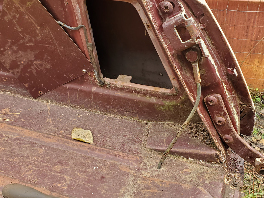
Right side access panel pulled up to allow access to inner fender/quarter to put nuts on the three bolts for the right hinge.
Inside of tailgate and bed after latching the tailgate closed. Note thread panel in the foreground, it has the three thread holes in it.
Outside of closed tailgate, there is a dent on the right side of the panel that will need to be addressed. The name logo will also need to be replaced, for aesthetics sake, and the dealership logo will need to be removed as I don't want some two bit dealership's name dirtying my car.
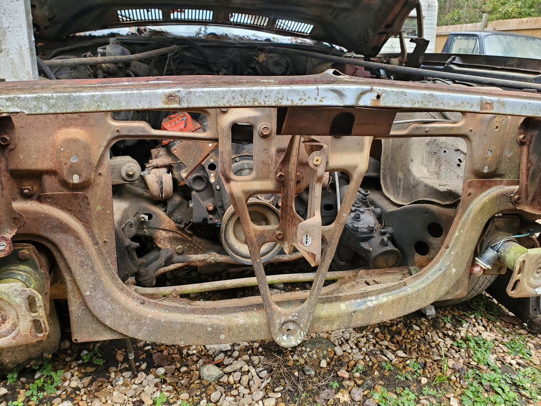
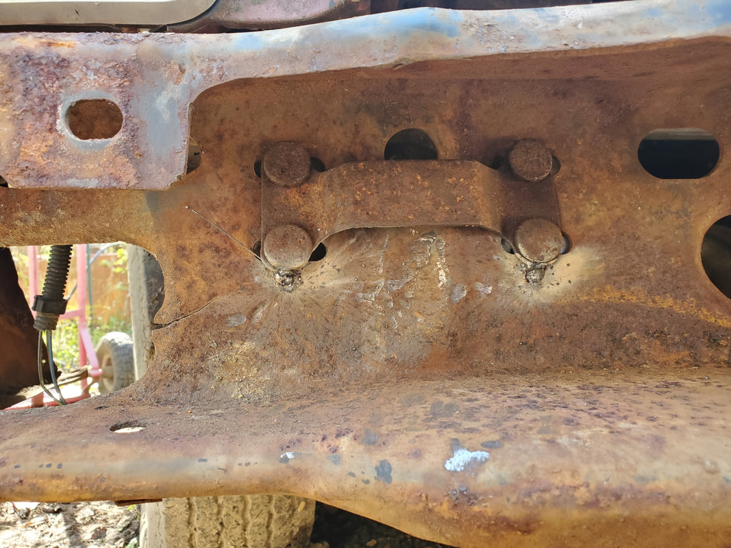
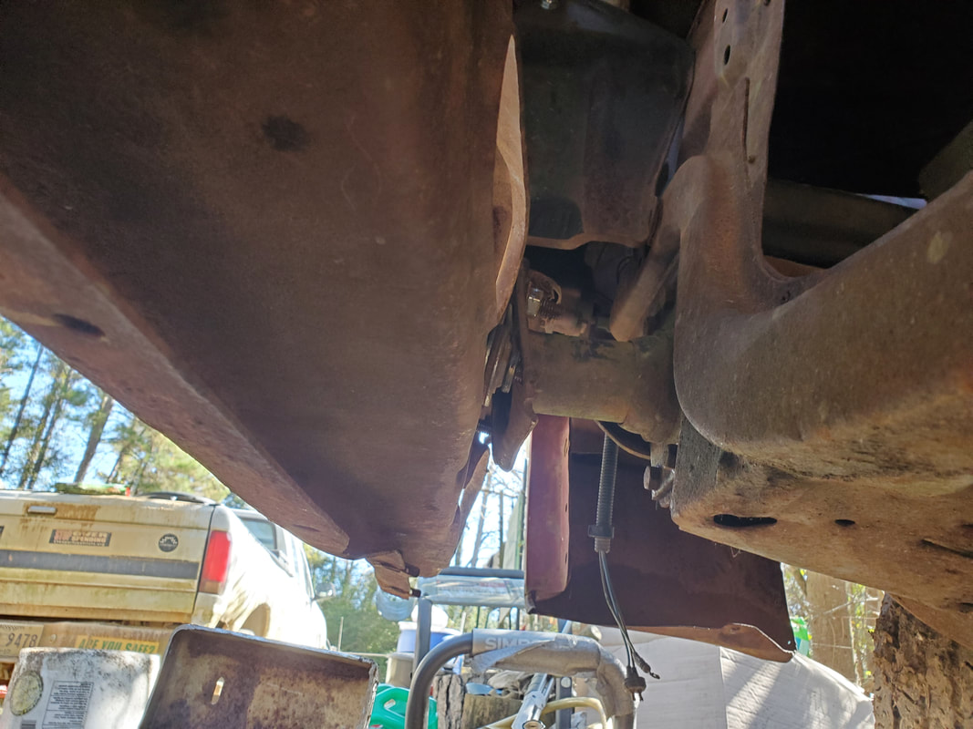
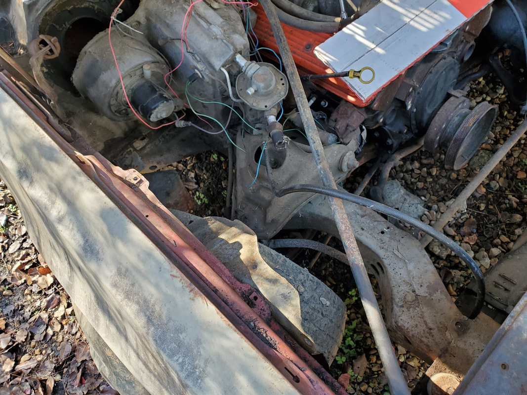
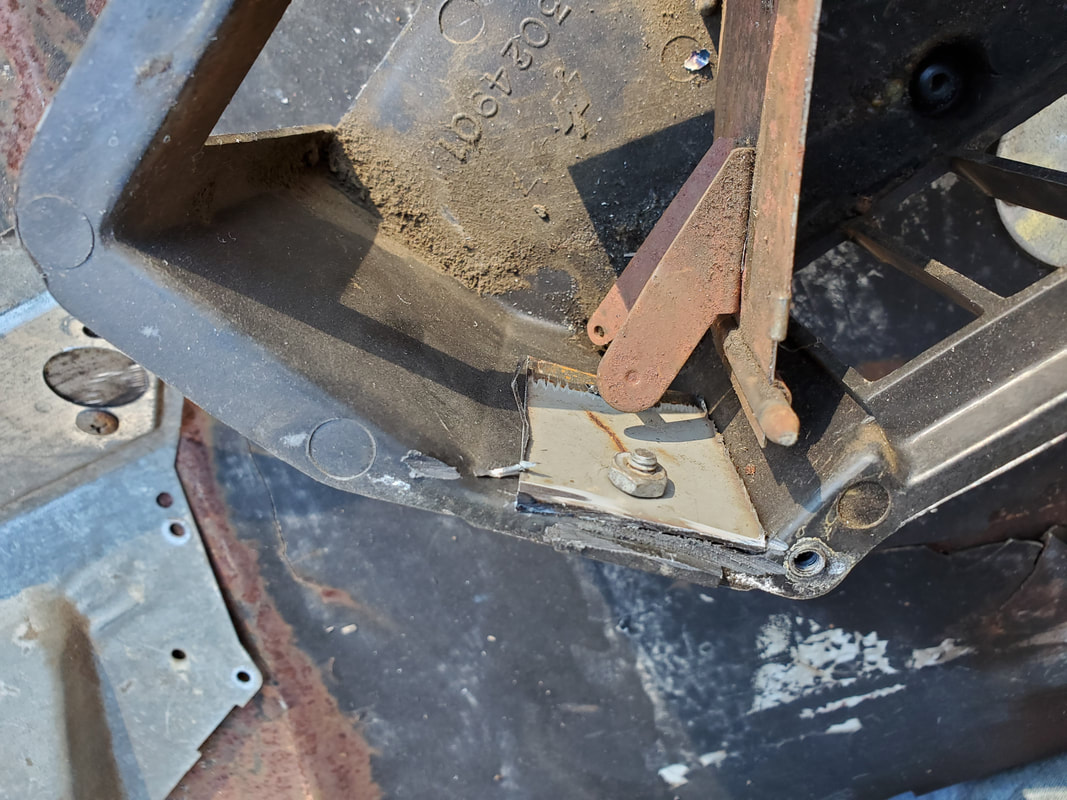
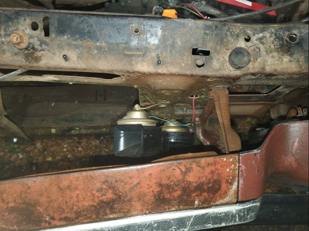
At this point my next move was sliding under the car. I made a crossmember when I installed the 700R4 and 305 V8. The crossmember is made from angle iron and some iron pipe to strengthen it and was held in place with a single bolt on each side just to keep the transmission's tail off the ground. I did pick up a factory crossmember from Texas with the rear bumper but the only problem is that cars from these years were made to have a single exhaust system as part of their detuning for emissions purposes. The exhaust manifold flanges pipe together into a Y pipe that goes into a single pipe routed through a catalytic converter and single muffler. Because of this it would make it difficult to have true dual exhaust on the car with that crossmember. The homemade crossmember actually rides low enough to allow pipes to pass over the top unrestricted. I do plan on reusing the homemade crossmember by adding a piece of flat stock crossways over each end of the crossmember then drilling holes on the ends of the cross piece to match up to the holes on the car's frame so the crossmember can be bolted up with two bolts like the factory unit and be nice and stable. I do plan on trying to use the factory crossmember by cutting a notch on the tube opposite of the factory depression then rewelding the metal in to create another depression to essentially turn the factory crossmember into a dual exhaust crossmember that still has the strength of the factory unit and ability to mount like the factory unit while still accommodating dual pipes.
The other thing is the old exhaust pipes. Most of the exhaust system is still present up to just behind the front wheels. Most of this pipe is either rusted or bent or both. The mufflers are still in good shape so they can be reused but I will probably have to use adapters welded in place to accommodate whatever size exhaust pipe I plan on using. I will have to hit the junkyard to get manifold flanges and donor exhaust pipe to make a system, including the axle pipes. Other option is installing headers and getting generic pieces of exhaust pipe including the axle pipes to make a complete custom exhaust system. Another bootleg option is welding 45 degree bend pipes to the ports of the exhaust manifolds then use couplings to attach the exhaust system to to these hybrid bootleg "headers". We'll get it figured out when we get to the point that we need to make an exhaust system.
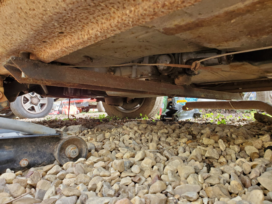
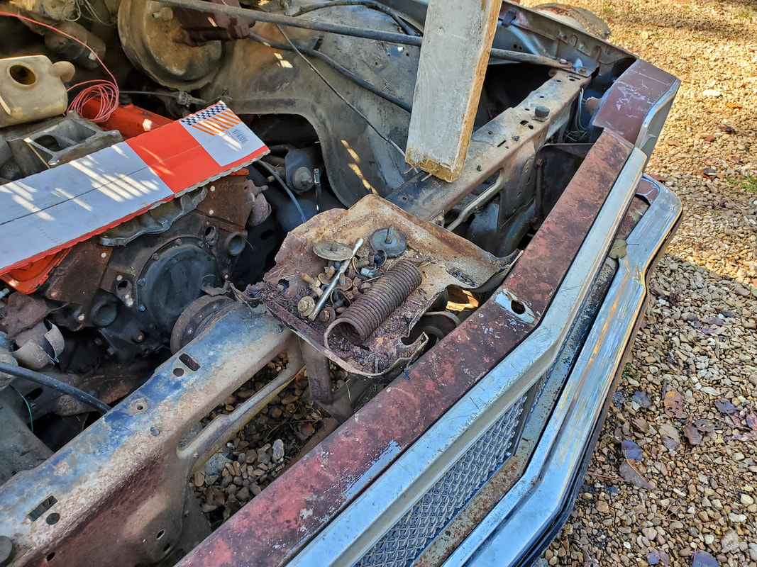
Homemade crossmember secured in place with single bolts on either side. Note the spacing over the top of the crossmember that allows pipes to pass over the top. Also note the end of exhaust pipe poking from the right.
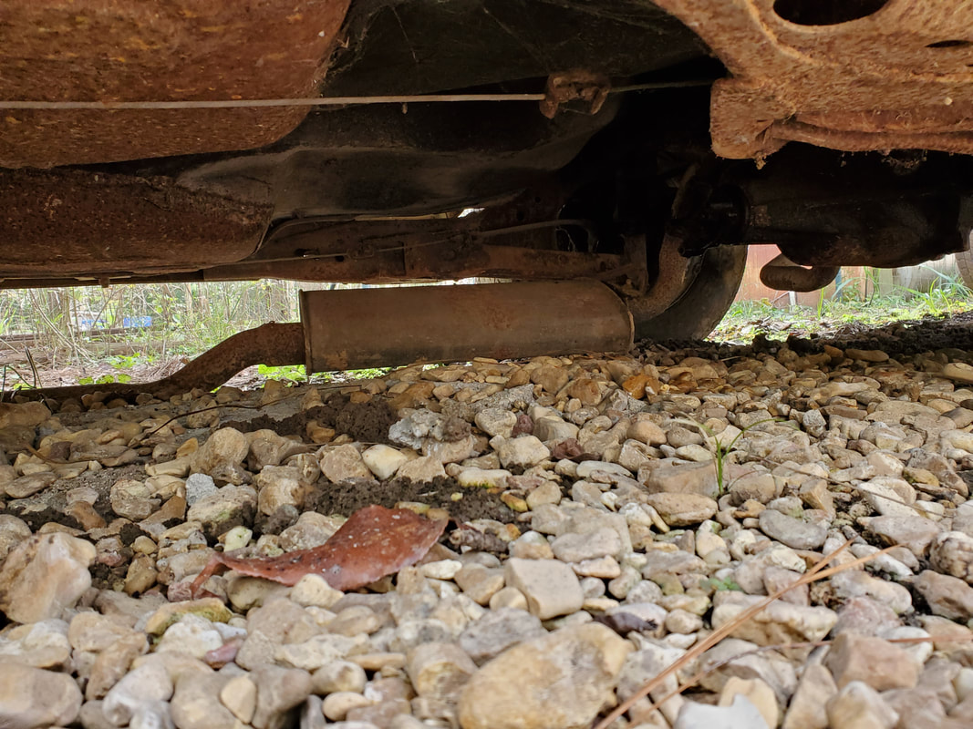
Old exhaust pipe in place that will need to be removed prior to installing a new system.
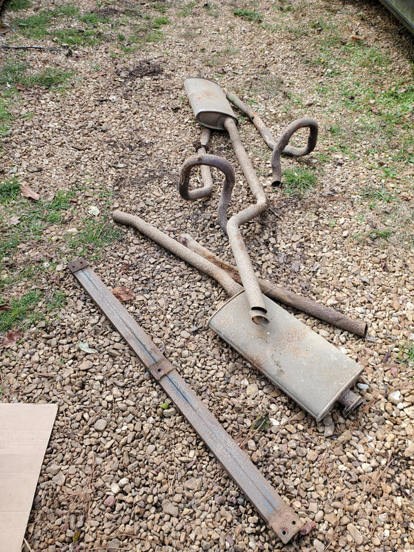
All the old exhaust pipe that was cut free from under the car. Since the old system isn't going to be reused, it doesn't matter how much I cut it up, I kept the mufflers intact as I will most likely reuse them as they are. Also note the homemade crossmember staged among the exhaust pipe.
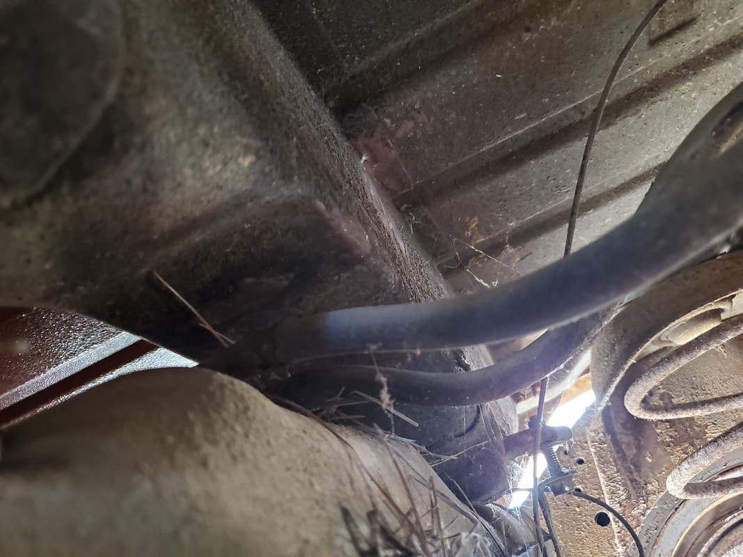
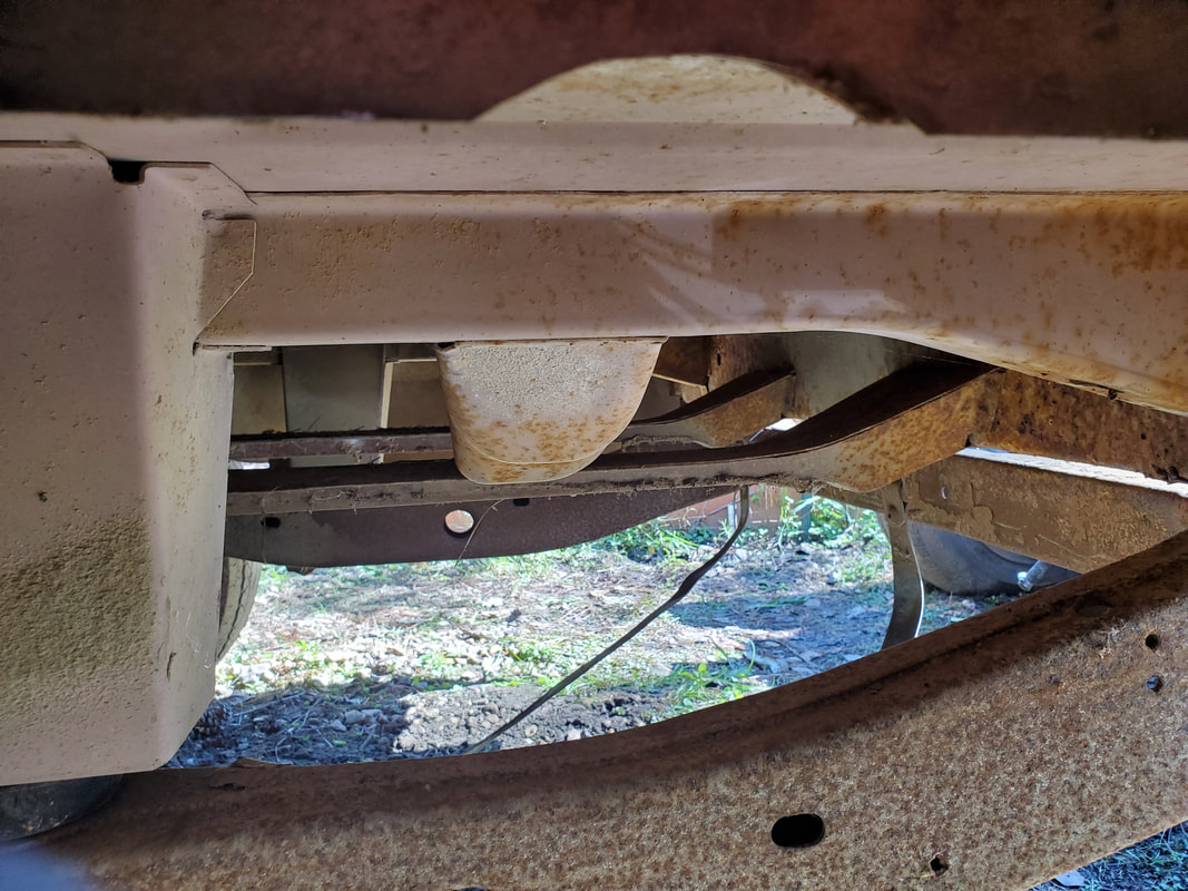
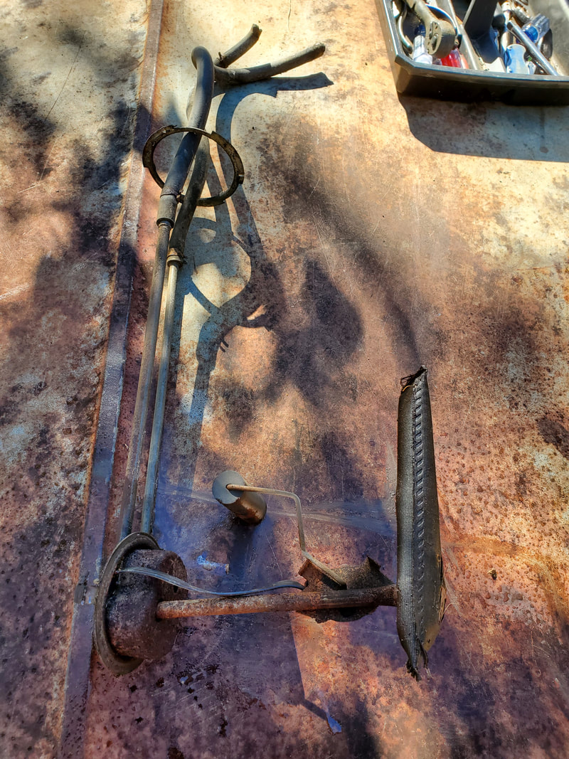
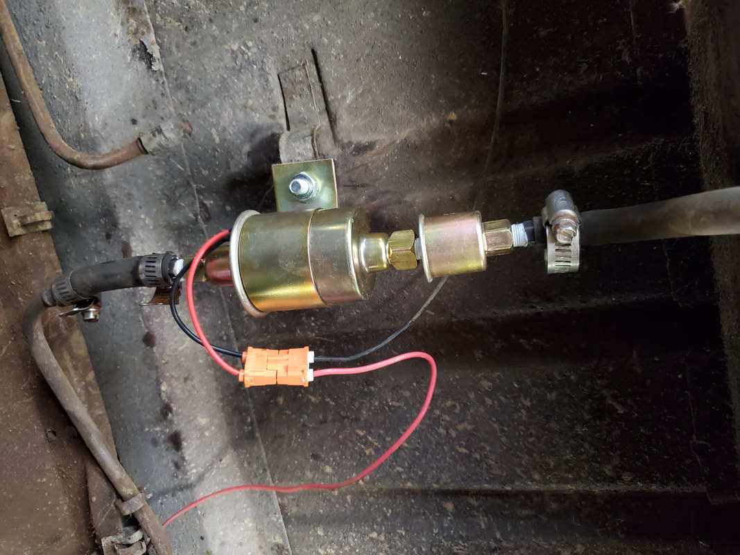
While I was under the car I turned my attention to the fuel tank. I needed to address this component on the premise that if it needs replacing, I would need to make provisions to get a new one. It's held in with two straps, with each strap held by a single bolt. The filler tube is attached to the tank as one piece but there's plenty of room under the car to move the tank out without incident. There's two fuel lines going to the tank's sending unit, one being the main line for the carburetor and the other for the evaporative emissions system, feeding into a charcoal canister, which I removed earlier. I need to also check to see if the sending unit is in good shape as well as the tank in case I need to replace that just as well. I plan on installing the generic electric fuel pump as close to the fuel tank as I can so it won't have to work hard drawing from the tank. There's a spot just in front of the tank where I can add the pump, only having to trim a little bit of metal line from the main fuel line to make room. Conveniently the tank still had some old gas in it, so I had to take care to be able to catch the tank without it injuring me or itself when it comes free. Luckily I propped it as I pulled the 2nd strap free so I was able to guide it to the ground and out all the way.
Two fuel lines going to sending unit on top of fuel tank. One hose goes to the main line feeding the carburetor and the other feeds the charcoal canister in the evaporative emissions system.
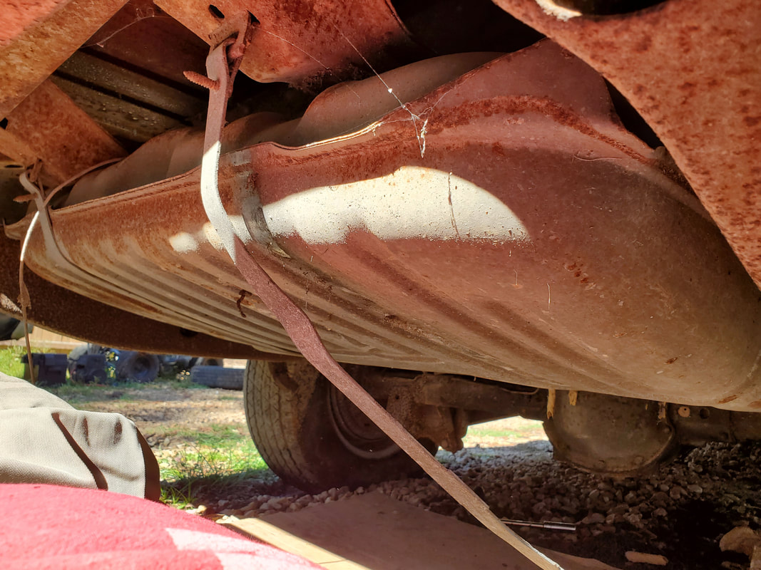
One strap down on tank. Since tank was filled partially, I had to brace myself underneath with my chest and arm in the way to help catch and slow the tank's descent after removing the last strap bolt.
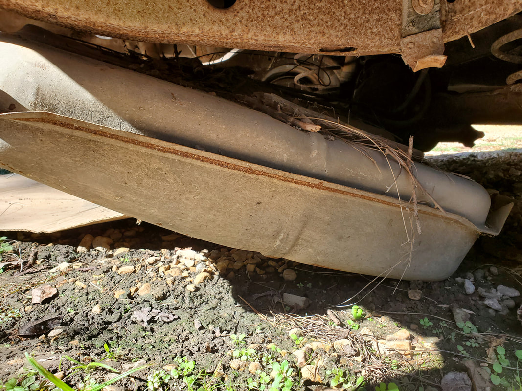
Fuel tank hanging down to the ground after removing both straps.
Fuel tank on the ground and partially removed from under the car.
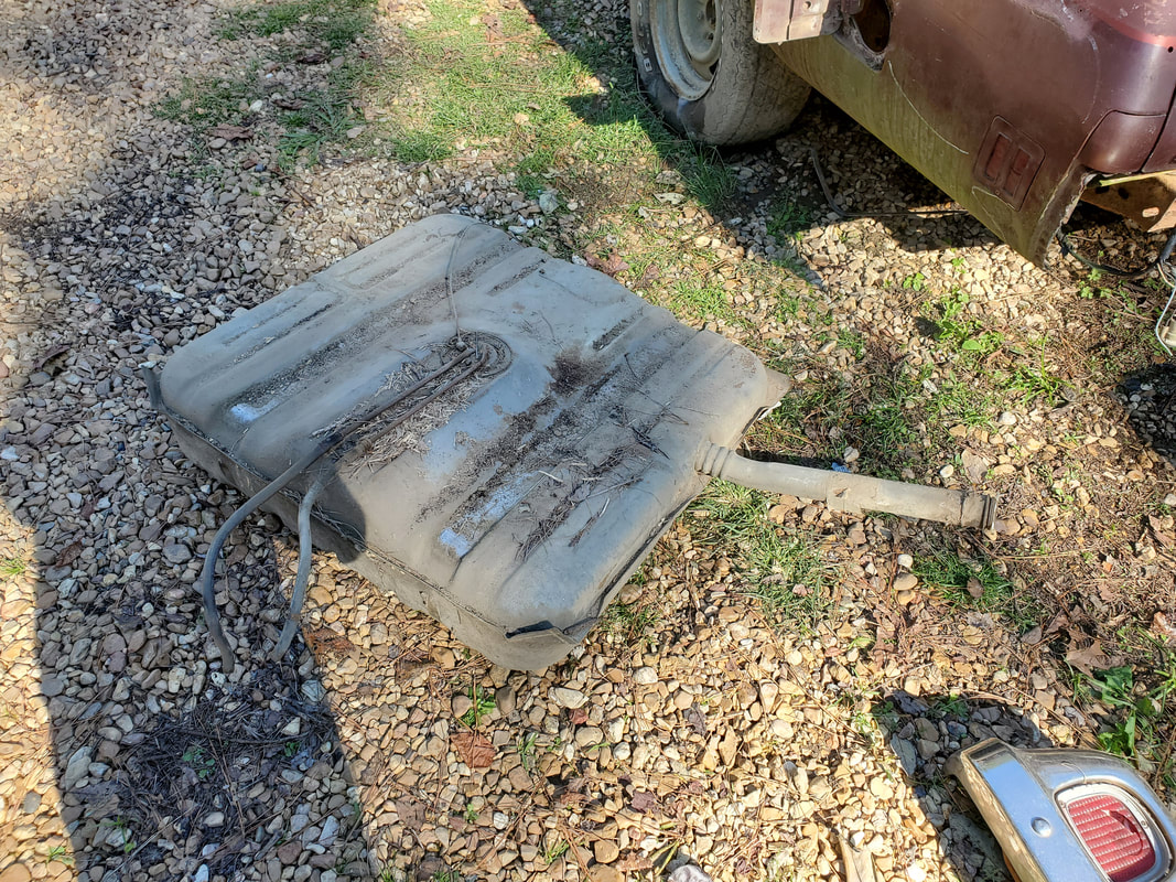
Tank removed from under car. Note the integrated filler tube on tank and twin fuel lines on top of sending unit in middle top of tank.
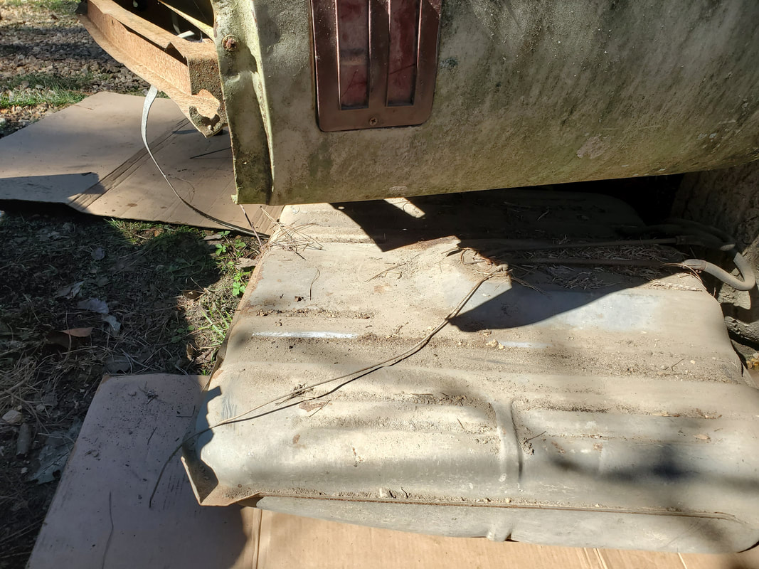
Empty space under bed where fuel tank used to sit. Space between frame rail and bottom of bed in foreground is where filler tube passed through up to the filler door on left side of car.
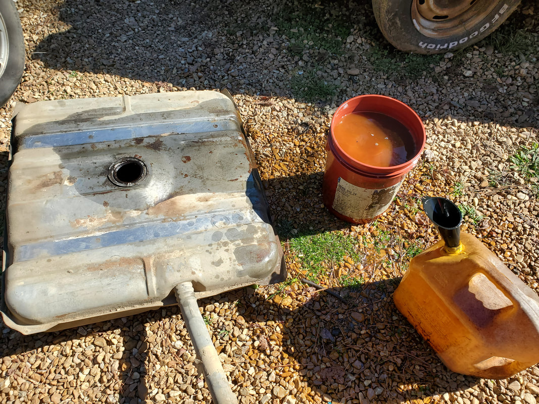
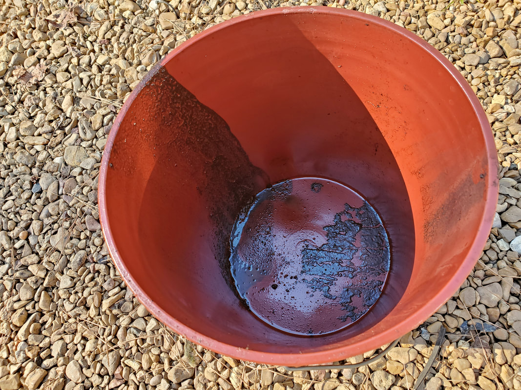
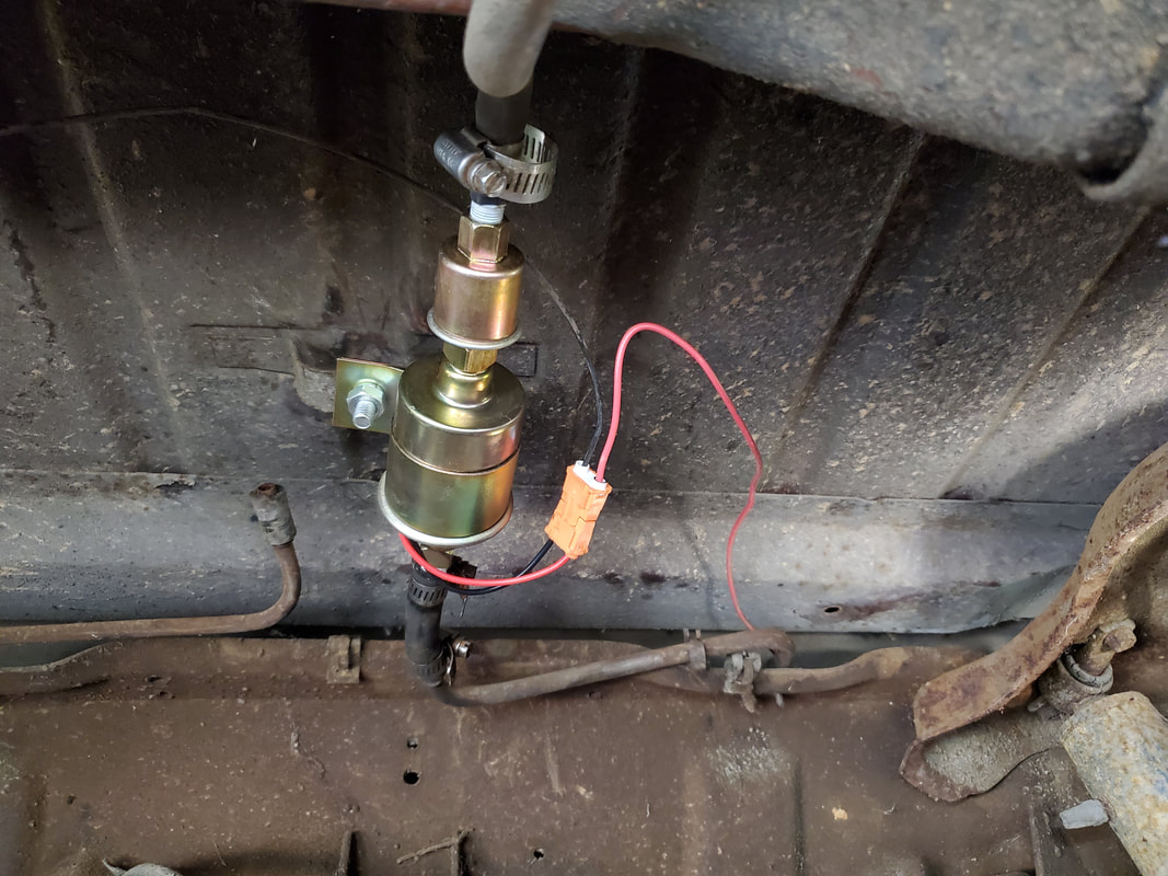
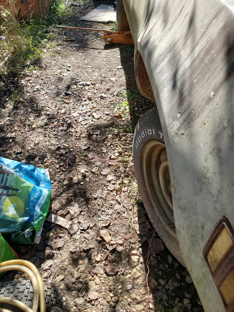
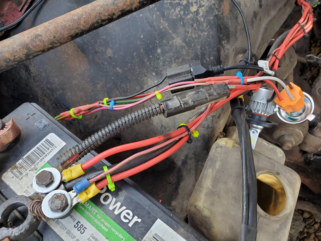
After dropping the tank there was still a matter of getting the old fuel out once I pulled the sending unit out. I couldn't just tip the tank on its side and let the fuel pour out the filler nozzle since the nozzle actually extends into the middle of the tank, guess there's some reason for this design concept, harder to siphon, harder to let vapors out when the vapors rise and can't just go up the nozzle but instead to the sending unit where the vapors travel up the fuel line to the charcoal canister. Who knows. I had to tip the tank upside down and dump the fuel out into a 5 gallon bucket. As for the sending unit, it was pretty much shot, it would need replacing anyway. The tank though was luckily in good shape, good thing, because replacement tanks for this car are around $300. In the meantime I did get the electric fuel pump mounted under bed with the modified hose lengths to allow for the pump to be situated in line with the old fuel line path. I also ran a power line to the front of the car to be run through the firewall to be wired in to the new electrical system when that is established.
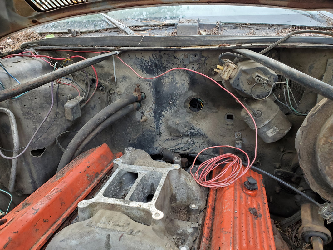
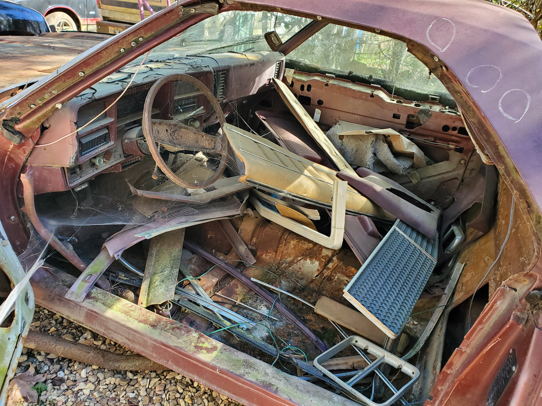
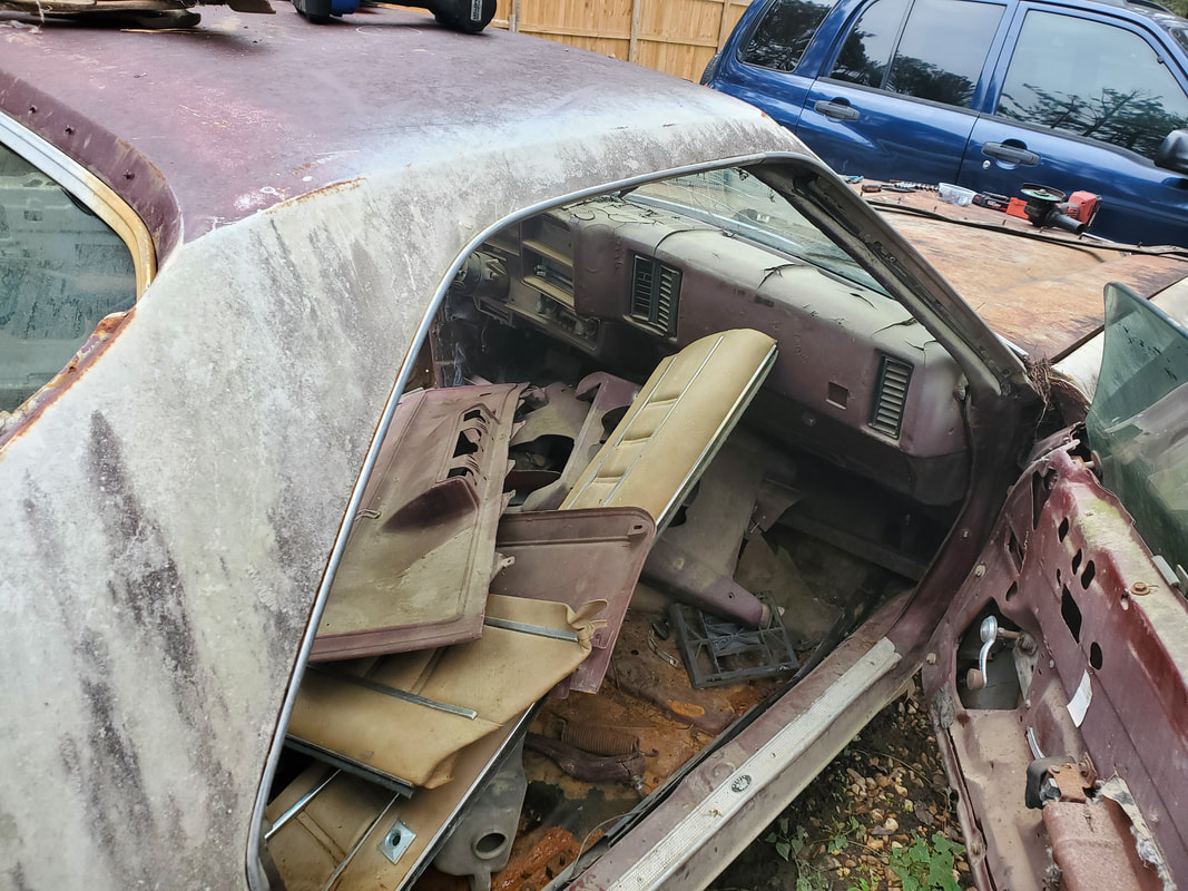
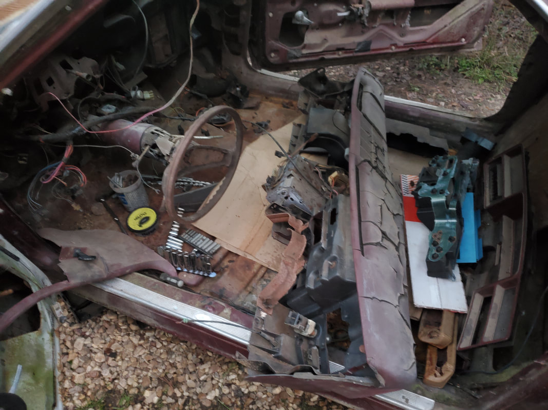
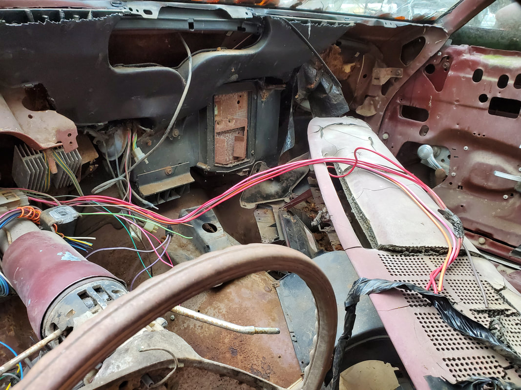
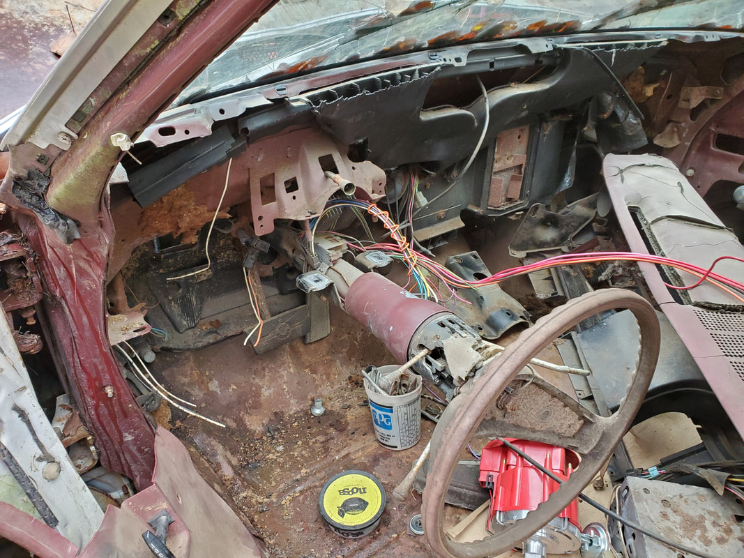
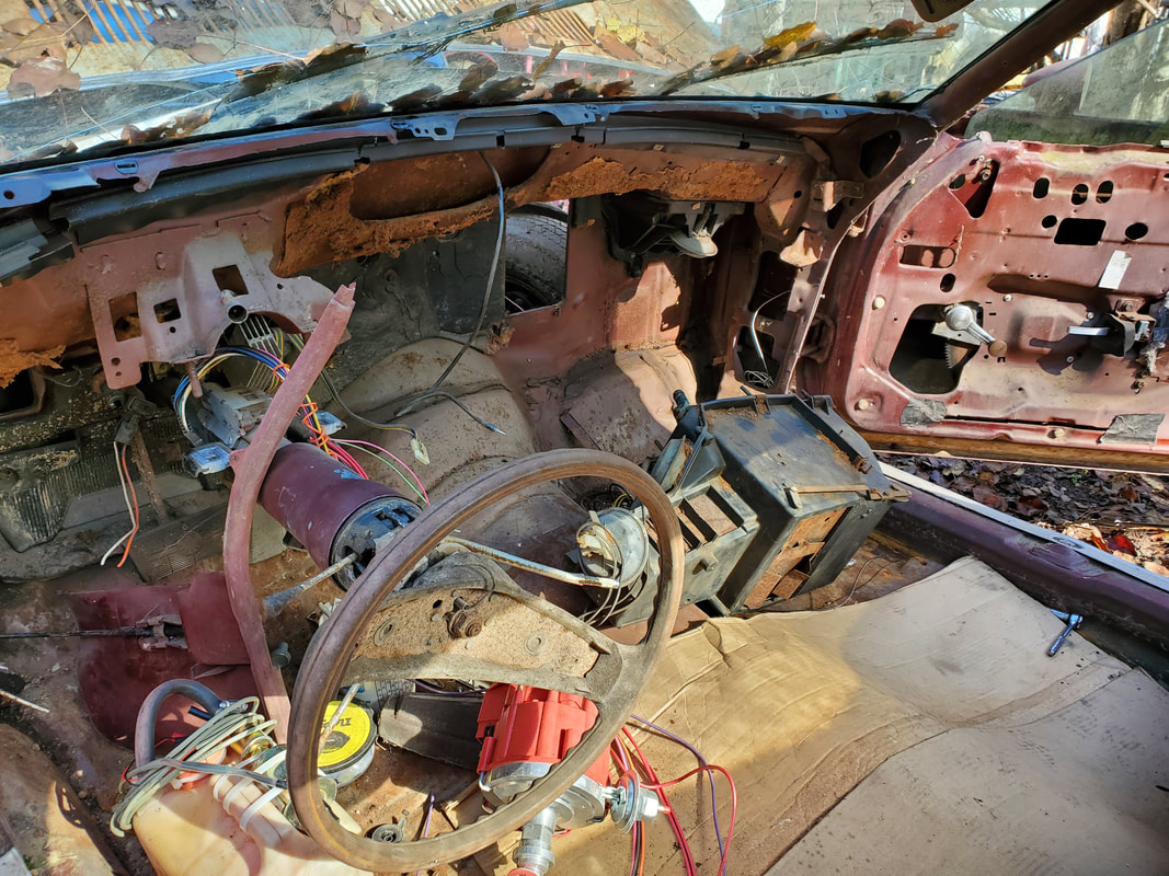
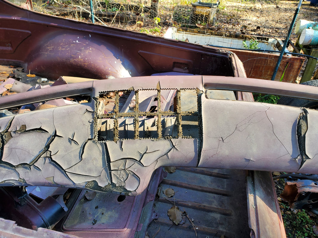
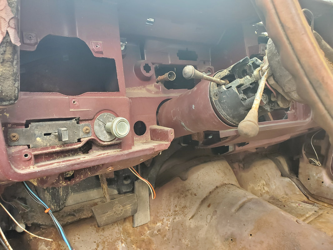
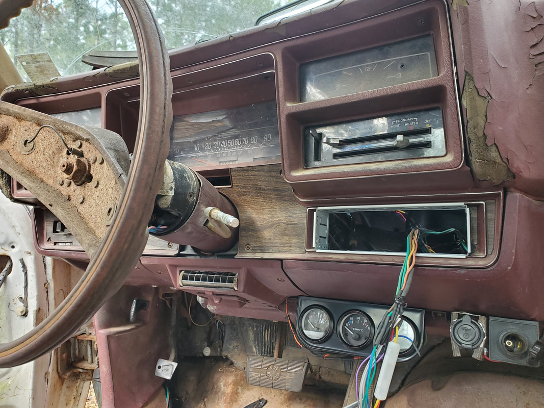
After having gone as far as I could go with the fuel system, I turned my attention to the interior. I wanted to get things cleaned out enough to get ready to start pulling the dash. There were several interior pieces like the door panels and a few other interior pieces that weren't ready to go on since they would be in the way when I got to the rewiring. Also since part of the door panels had particle board in them, they would have to be stored inside somewhere so the elements can't destroy them. The regular plastic pieces were good to store in the bed. Once the panels were sorted through I did find a couple of fender extension pieces that go on the ends of the fenders, right behind the corners of the front bumper. I also found the sun visors. I installed these parts since the sun visors wouldn't be in the way and the fender pieces needed to go on anyway. I cleaned the interior floor good, getting all the dirt and loose crap out. The fun then began. I had to disassemble the dash little by little to find the different bolts that would need to come out to get the whole dash frame pulled. I pulled out several pieces before finally getting the dash all the way out. This also included dropping the steering column. With the dash finally out, I can now start my work on the HVAC system and the rewiring.
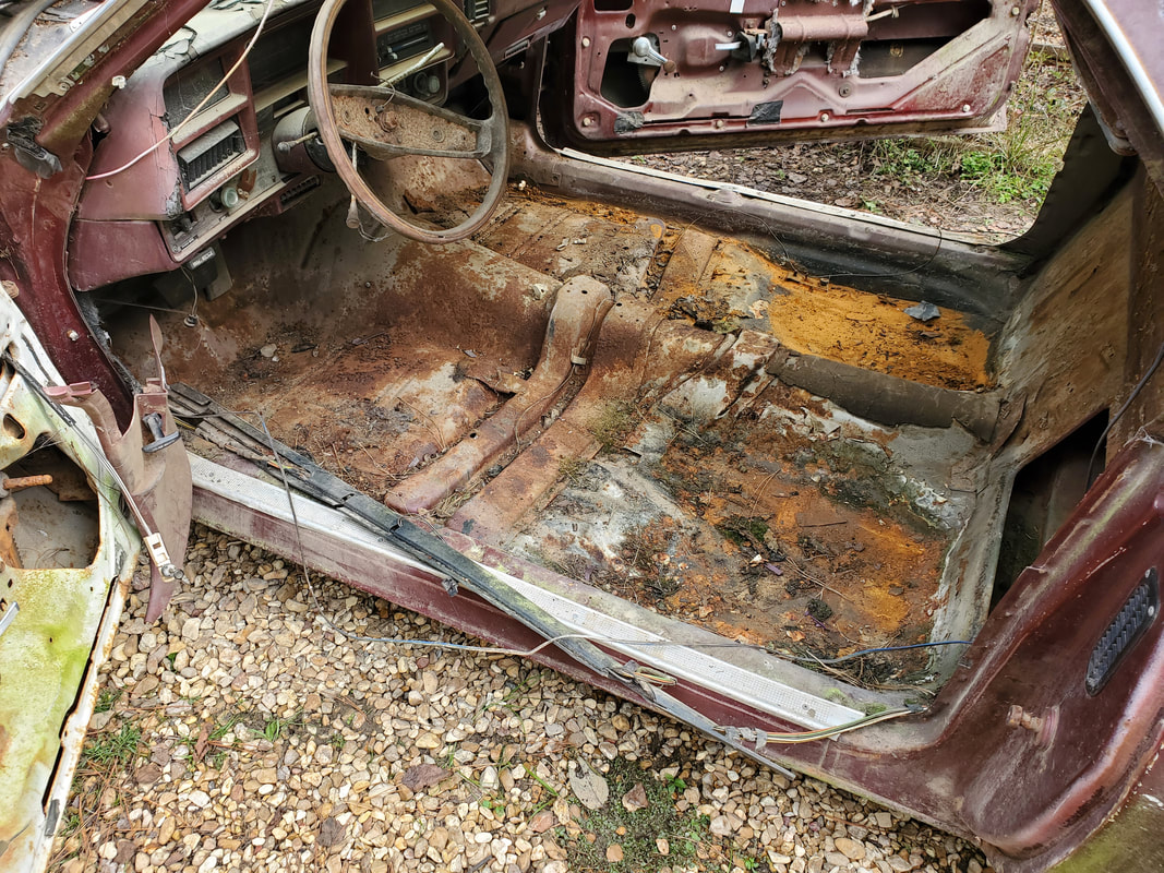
The interior of the car after removing the loose interior panels, note all the loose dirt and shit on the floor. I don't want to be laying on this when I'm pulling the dash.
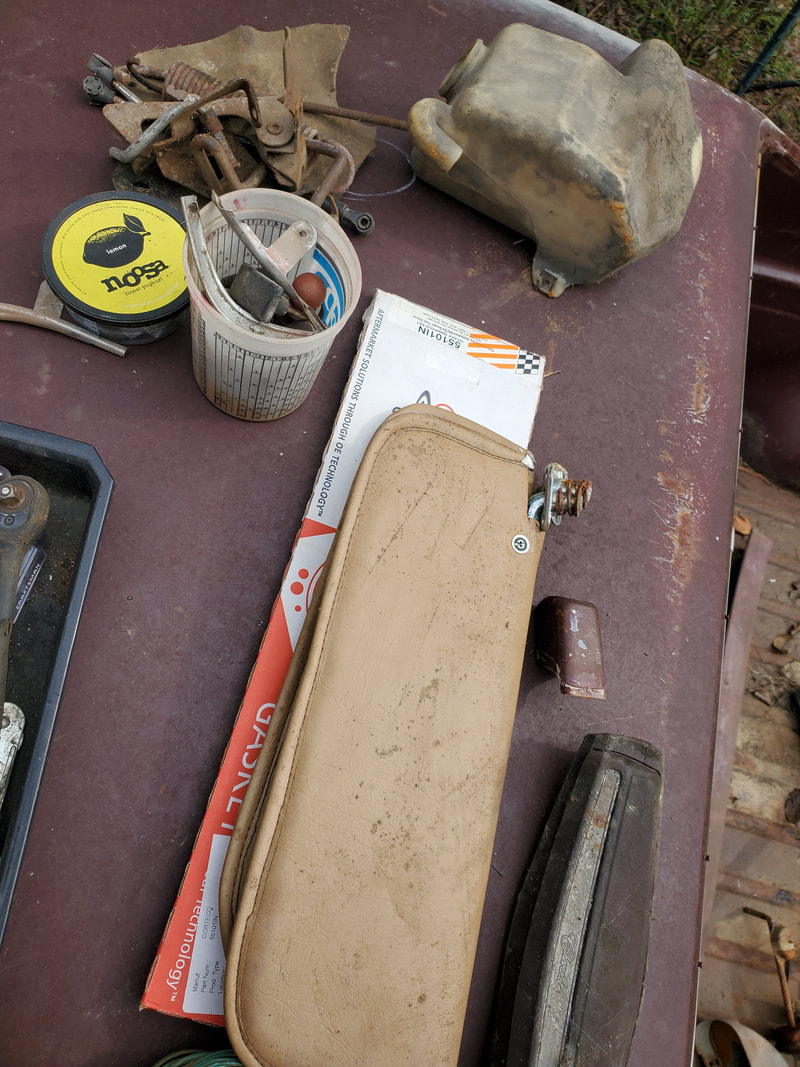
The sun visors, and a couple other loose parts pulled from the batch of parts.
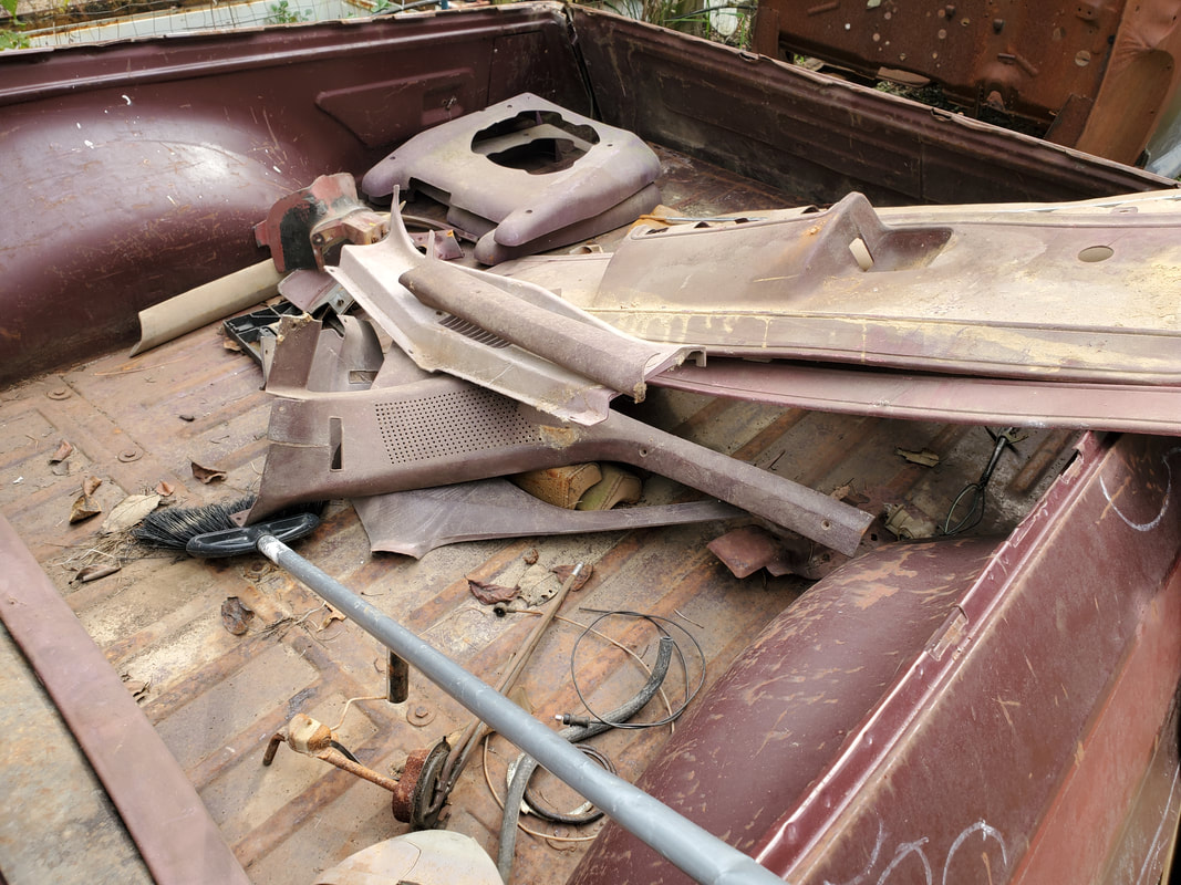
All of the plastic interior panels that were pulled from the cab's floor and stored in the bed of the car to keep it out of the way.
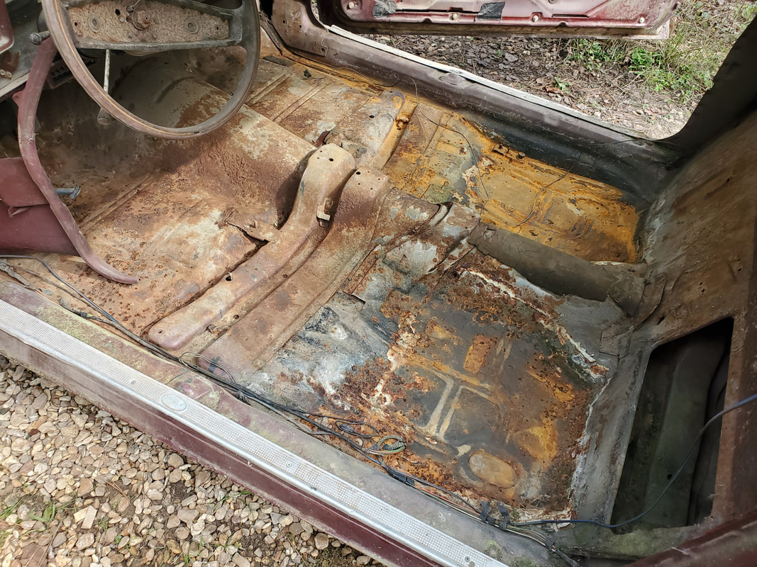
After vacuuming out the floor, the interior is now clean enough for me to be able to lay on the floor while going under the dash to pull bolts.
The dash started coming apart. I pulled a large piece of the dash out then started pulling other pieces from the dash, like the ash tray, among other things.
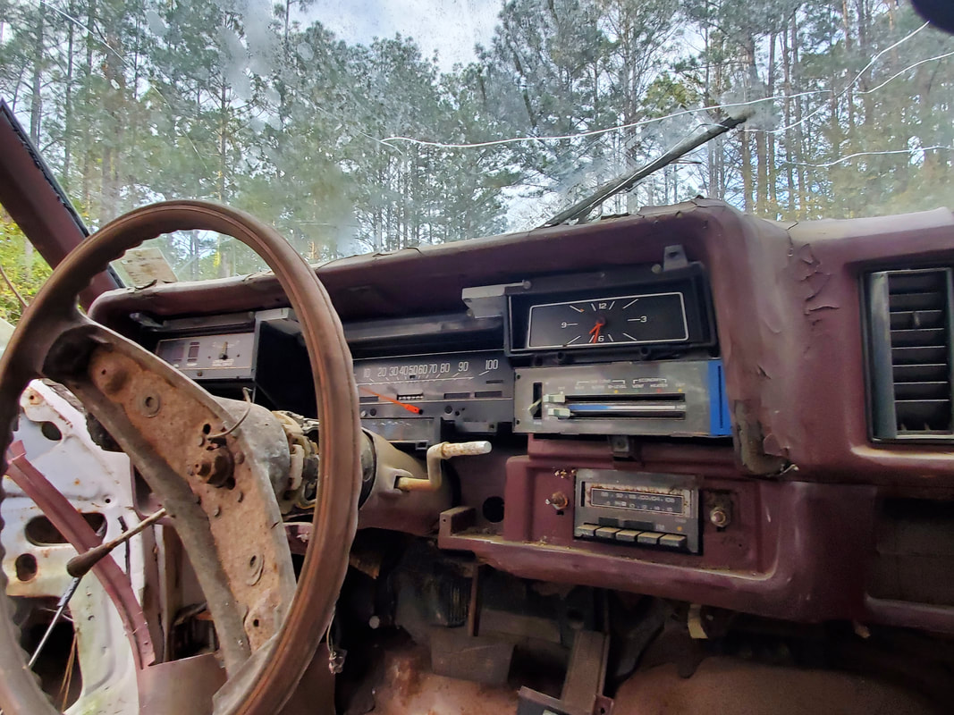
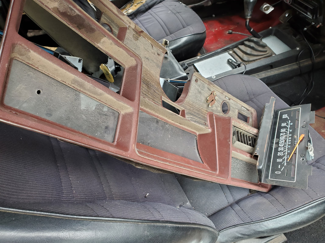
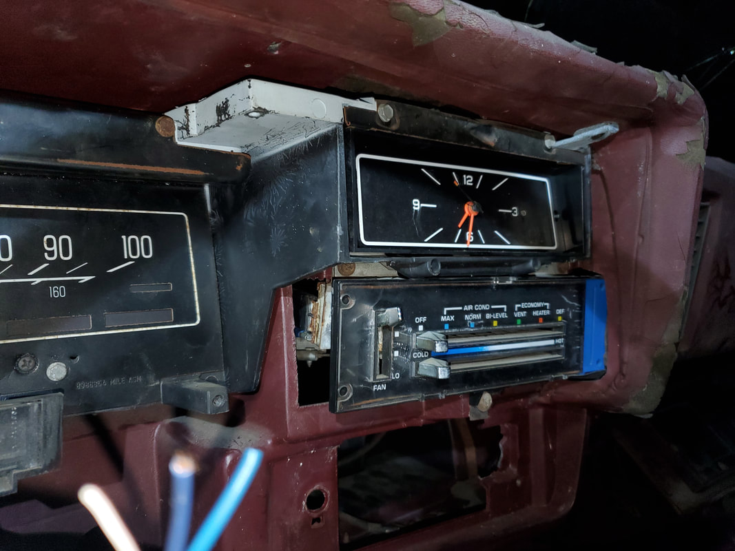
I had to pull the gauge panel molding panel from around the gauge panel. The gauge panel also had to some out, among other things, in order to expose more bolts to free up the dash frame.
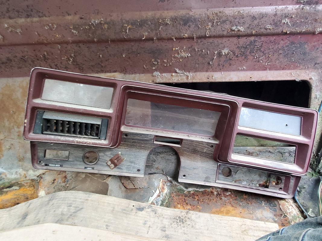
The gauge cluster trim panel, removed and out of the way. Another large piece of the puzzle removed. Luckily this piece is in good shape as well since I don't want to even contemplate the cost to replace one of these panels, if I could even find one...
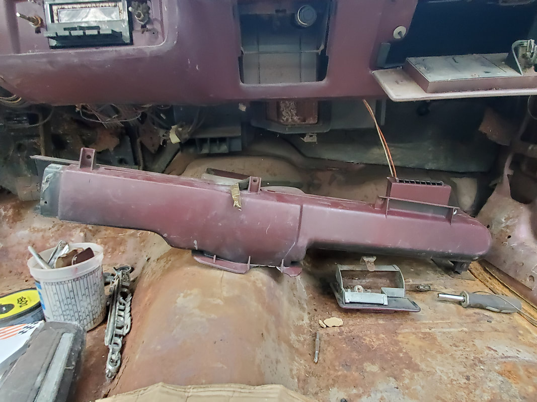
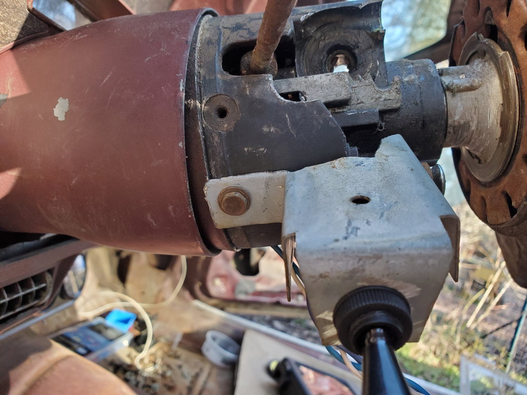
After removing the bolts holding the steering column, I finally got all the bolts out that held the entire dash frame in place. I was able to pull the dash frame free and out from the front of the cab.
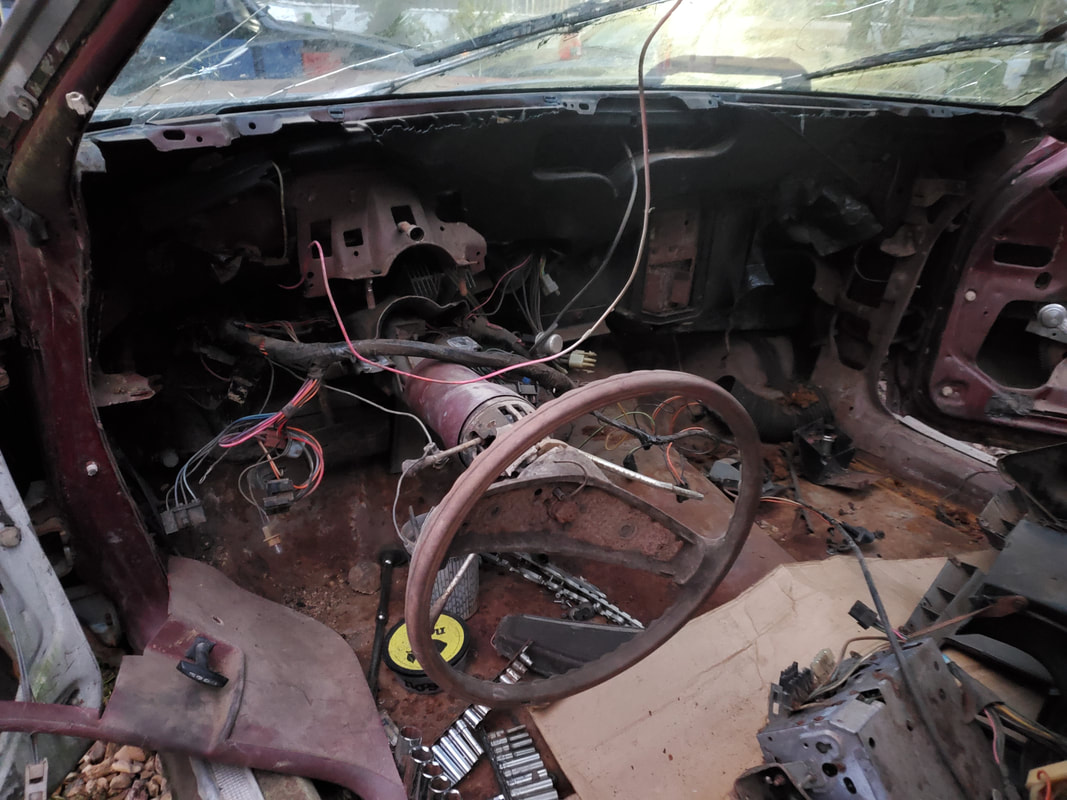
The front of the cab sans dash. Now I can work on the HVAC box, reworking how the system is laid out regarding ductwork and blend doors. I'll redo this system like I did the other cars I worked, where the defrost and chest level vents are both open all the time, so heat or cold can be blown equally over the window for defrosting and regulating the temperature at chest level. I can also pull the remaining wiring out in preparation for the rewiring of the car, which will also include mapping out the loads so I can clip the plugs from the old wire harness, like I did on the Dodge and LUV. The fun part is going to be putting all this shit back together though....
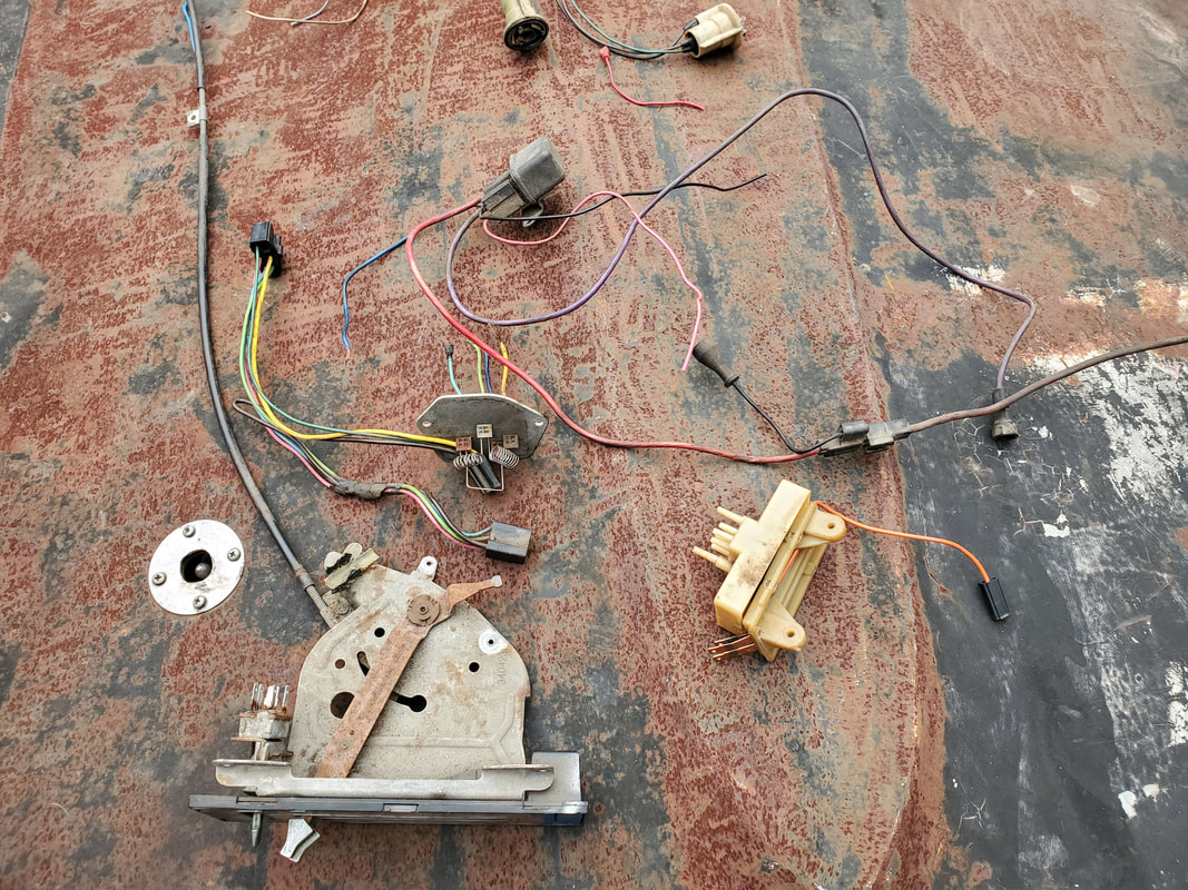
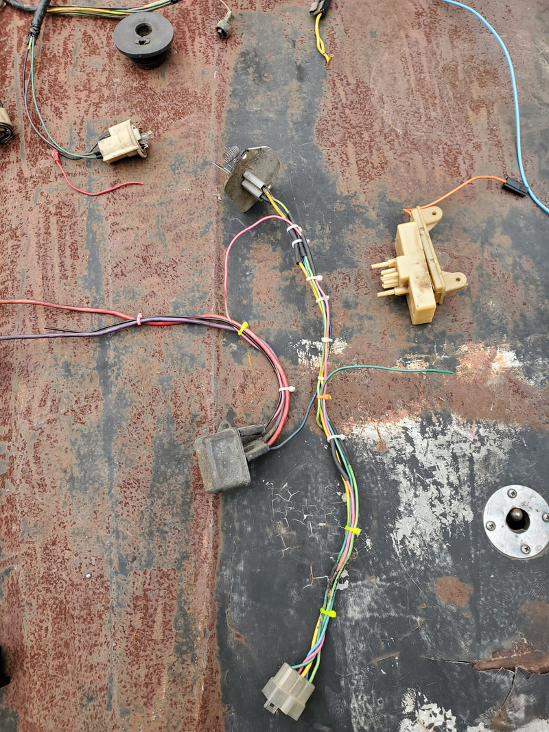
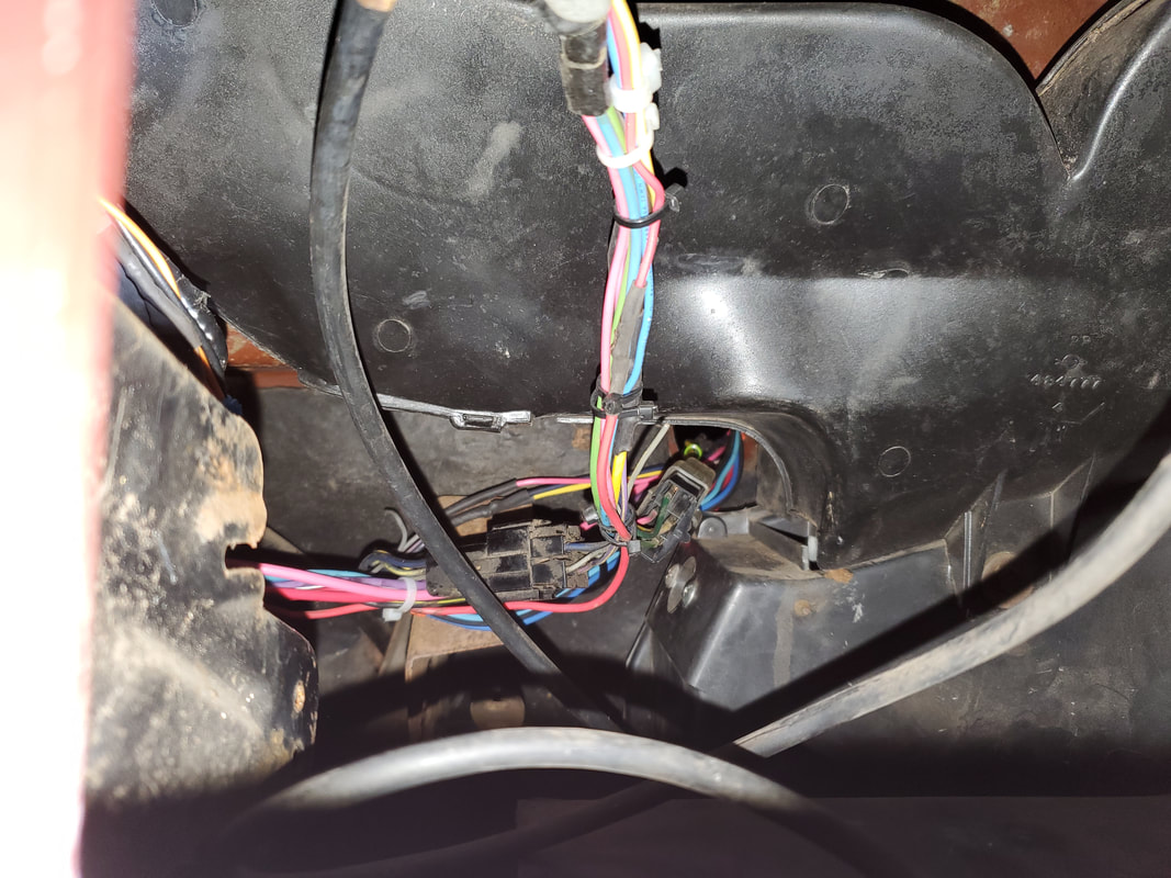
With the dash pulled free I was able to start pulling out the interior wiring. I took the time to cut the plugs free that will be needed for the different loads. Each plug was cut free with up to a foot of wire tailing the plug in order to have plenty to connect to later. Some plugs and other things like light fixtures were set aside as I may reuse these components in the new wiring. Some devices have yet to be identified but have been set aside as well in case they may be useful in our rewiring of the car. The old fuse box and the bulk of the old wire harness came out, leaving just the plugs with their pigtails. I decided to do the wiring differently than the way I did it in the other cars. Instead of running long individual circuit runs from the fuse box to the load. I plan on running a single power wire from the fuse box along a planned route through the dash then tapping off of that wire at different points in order to feed power to the loads to be put on that one circuit. This should keep things pretty simple and neater as there won't be as much wiring in the dash.
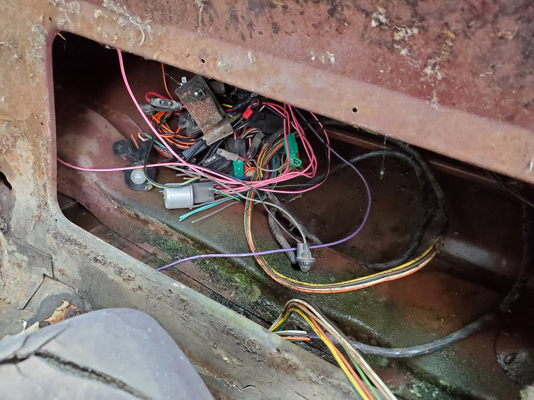
Fuse box and old wire harness in place, all of this will have to come out.
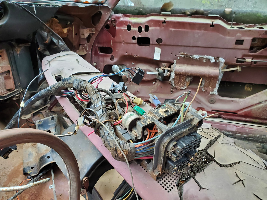
After cutting plugs and some wiring free from each plug, I was able to get the fuse box removed from the inner firewall along with the bulk of the wire harness that won't be reused.
Hole in the firewall after pulling fuse block that had the junction plug for the engine bay wire harness.
A larger bundle of wires from the steering column, longer than usual due to a couple of oddly placed wires, I cut everything even so the connections will at least be somewhat uniform versus staggered at various lengths.
Another wire bundle and plug on the steering column that has some extra wire cut to aid in reconnection.
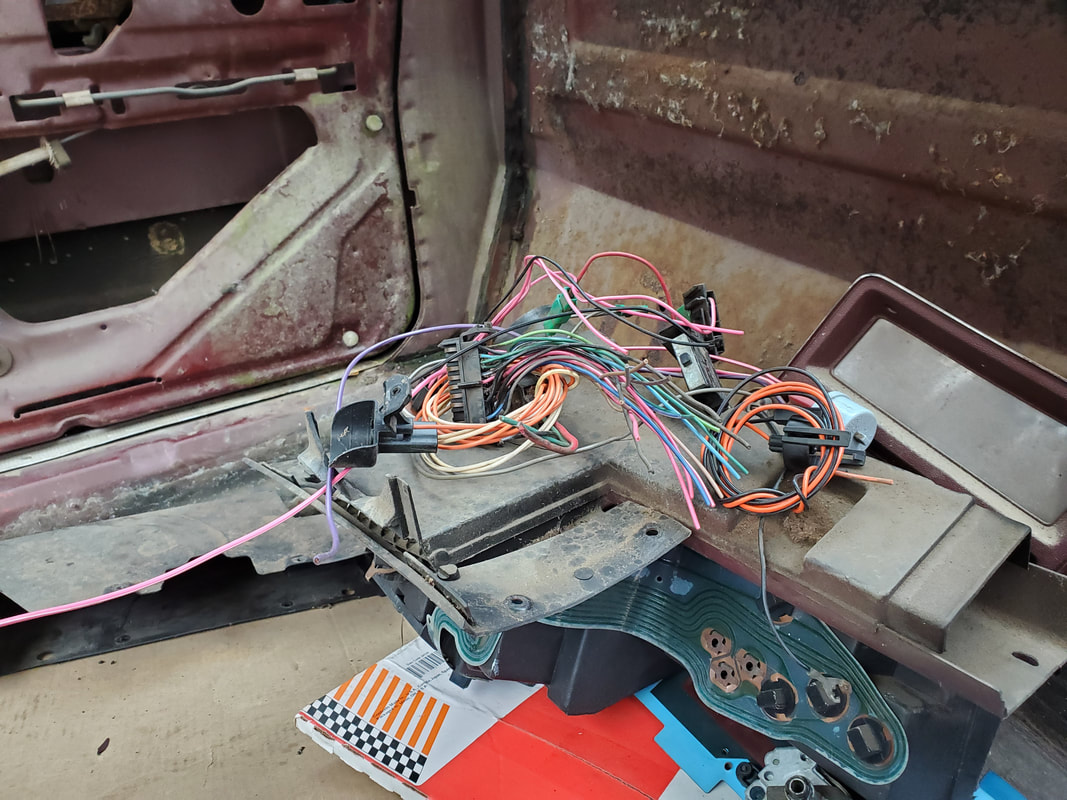
Some extra electrical plugs and components set aside on top of the gauge cluster during the wiring disassembly.
More components set aside after the separation of the wiring harness.
Inner firewall after removing the wiring harness and associated components.
Gauge cluster and trim panel stored away in 69 Mustang for safe keeping out of the elements for the time being. I need this stuff out of the way for when I end up having to lay on my back or in other awkward positions in the car during the rewiring.
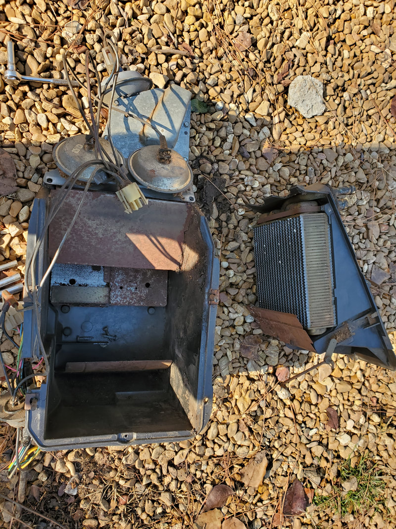
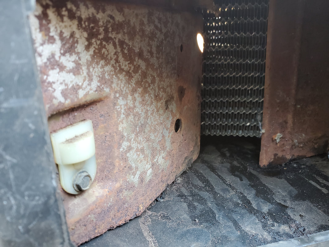
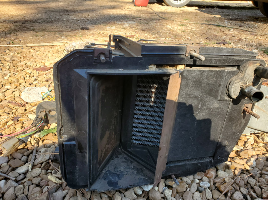
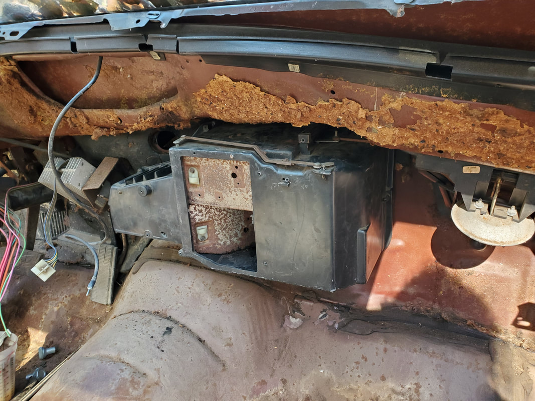
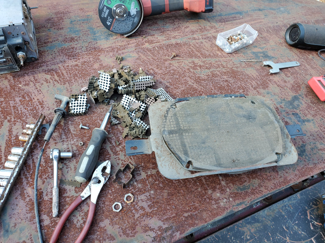
With the wiring pretty much taken care of as far as separation and removal, I turned my attention to the HVAC boxes. There's an inner and outer box that would have to be pulled, I started with the inner box. I had to pull these apart in order to clean them as well as to see how to rework the system to simplify things. I plan on only having the blend door for the hot and cold selection and the defrost and floor or chest level vents, blowing pretty much at the same time. After removing all the fasteners I could reach for the inner box, I found there was one more retaining nut for one of the studs, on the inside of the outer box. In order for me to remove the outer box I had to remove the fender shield in order to access a couple of bolts along the bottom of the box. With the fender shield out along with the outer HVAC box, I was able to further investigate the boxes. In order to clean the outer box I had to further separate the box into its two halves of the shell its made up of, so I can pull the evaporator free. I will have to clean some deposits of dirt and other crap from the coils in order to ensure proper air flow later. I don't want to have to replace this component as I'm sure its expensive. I will probably replace the heater core in the inner HVAC box since most of the time old heater cores are clogged enough to not be able to work efficiently. I removed the hose stubs from the heater core and one old hose from the dryer on the evaporator so these hoses will all need to be replaced later. The main thing is the HVAC system is removed.
Battery tray removed prior to fully removing the fender shield in order to reach the lower bolts on the outer HVAC box.
Fender shield removed to open up the workspace to get the HVAC box out.
Outer HVAC box removed and pulled away from the firewall. I can now clean the inside out.
Outer HVAC box separated further, allowing for removal of the evaporator. Note the trash on the coils that will need to be removed if I hope to have this thing move air efficiently.
Inner HVAC box pulled from inner firewall as well. I can clean out the shit from the inside of the box. The heater core will most likely be replaced as well.
With the HVAC boxes out I was able to do some examinations of both sides. It turned out the heater core in the inner box had nice clear coolant in it, which would tell me that its probably not clogged up with rusty trash from a cooling system that had mostly water in it. As for the AC evaporator, I had to run the thing under water and blow compressed air through the coils to blow out the 45 years of accumulated trash that deposited itself on the outside of the coils. Once that was clear I moved on to doing my retrofit of the inner HVAC box blend doors in order to modify the system to be more simplistic. The whole idea is to make the thing have a constant on chest level vent and defrost vent. I took the time to disassemble the box, removing the vacuum actuators and miscellaneous hoses that were attached. I looked at how the blend doors are situated and figured out a battle plan. The hot/cold blend door is the only one that uses a cable hooked up to a lever on the control panel so that will remain the same as this control moves the blend door in a fine tuning manner to control the blending of the hot and cold from the heater core and AC evaporator.
As for the other blend doors, I found the chest level blend door was a two piece unit that after looking at it, if I pin the top half of the door closed, it will allow pressurized air to build up in this intermediate area of the HVAC box. The lower blend door would be pinned open, which puts it against the heater core. This will allow a large amount of air to pass through the heater core and out the chest level vent while only allowing about a third of the air to pass up and over the opening that would send the air into the chamber that feeds the defroster and floor vent. As for the floor vent, that blend door was pinned closed, sealing it off from the exit to the floor vent and allowing all air to move up into the defrost vent.
Lastly I had to make patches to cover up the holes left behind when I removed the vacuum actuators on the HVAC box. With these openings patched up and the blend doors situated as I wanted, I was able to mount both HVAC boxes back in place on the firewall. I replaced the fender shield and concluded that part of the project.
Inner HVAC box disassembled prior to removing the unneeded components.
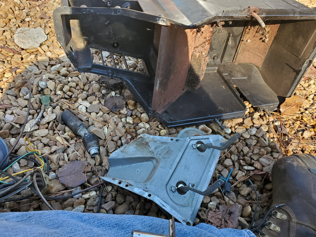
Metal plate holding two of the vacuum actuators. Both of these will be removed as they won't be used in the modification.
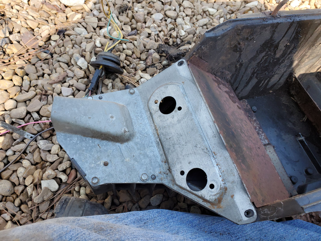
Plate with actuators removed.
Placing the blend doors in the positions where I would need them in order to achieve the effect of having constant defrost and chest level air.
Closeup of lower blend door in the open position showing how the heater core is exposed and will allow the pressurized air from the blower to swirl around in this area of the box, heating up more before exiting the chest level vent and defrost vent.
Blend door in open position allowing air to pass into the heater core. When AC is off evaporator won't get cold so the heat coming out won't be affected.
Hot/cold vent in the closed position blocking the heater core from getting air. Even though air will always pass through the AC evaporator, as long as the AC is not on, the evaporator won't get cold so it won't affect the heat coming out when in heating mode.
Single sheet metal screw secured in a plastic tab on outside of HVAC box to pin the linkage in the closed position for the lower blend door for the chest level vent. Note the sheet metal screw going through a hole in the box and into the upper blend door, through a drilled hole, in order to hold the upper door in the closed position.
Pinning the blend door for the defrost/floor vent using a plastic lobe inside the air plenum. A sheet metal screw went through a hole drilled in the lobe and into an existing hole on the blend door, holding it shut.
Inside of two actuator plate showing the cuts of the sheet metal and the nuts and bolts holding it in place.
Outside of actuator panel showing the neatness of the patch.
Single actuator port blocked off with sheet metal place using nuts and bolts to secure the metal in place using the existing bolt holes from the actuator.
Inside shot of the HVAC box showing the sheet metal patch and the screw/nut visible that's holding it in place.
Inner HVAC box remounted against inside of firewall.
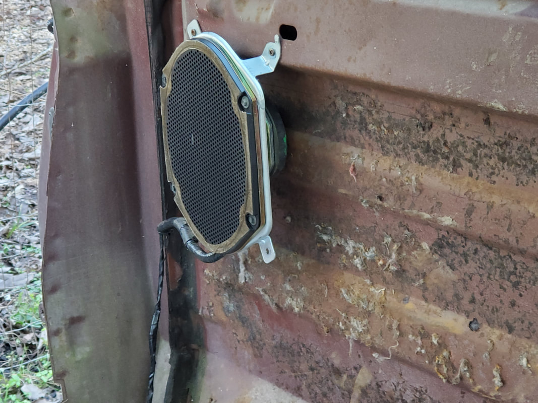
I decided to take a diversion and play with the dash frame, removing things from it, prior to my rewiring job since my fuse box came in. I removed the single speaker that was in the top middle of the dash. At the same time I cut out the rotted padding that covered the speaker area so I can replace it with an aftermarket speaker cover to make things look better. I thought about putting a 3 way speaker in here since with the modern digital stereos, sound quality for some songs will be shitty unless you put an external tweeter in with the regular speaker. If I put a 3 way in the dash I'd have to cut out the metal grate area, completely opening things up. My more likely alternative will be to install 3 way speakers in the two spots behind the seats where a pair of shitty speakers currently sit. These two would handle the majority of the load and a regular speaker in the dash can supplement those two speakers. That third speaker would have to be connected to one of the left or right channels on the stereo since the two for the rear would be occupied. As for the stereo itself, after being impressed that it was an 8 track stereo deck, that was rather heavy, I pulled it out. I'll have to cut out the opening on the dash to accommodate a single DIN stereo kit that would fit neatly in place and allow me to utilize a modern single DIN stereo. I'll end up using a media player since I hadn't used CD's in a long time and even fell away from plugging flash drives and micro SD cards to the car's stereo. Since most of these stereos use bluetooth tech, I just sync my phone to the radio and play music from my phone through to the radio.
Speaker area cleared of both speaker and rotted padding.
Speaker and rotted padding outside of dash.
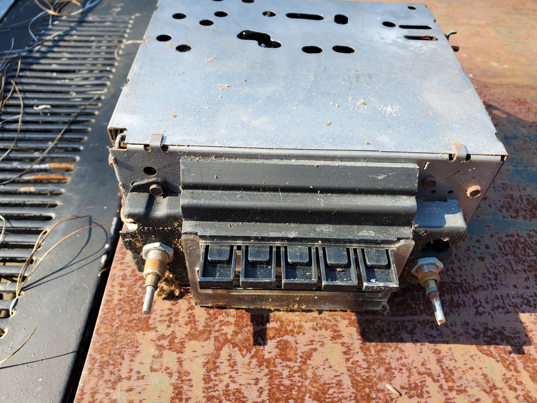
Old 8 track stereo system, this thing is super heavy.
|
|
|
|
|
|
|
|
|
|
|
|
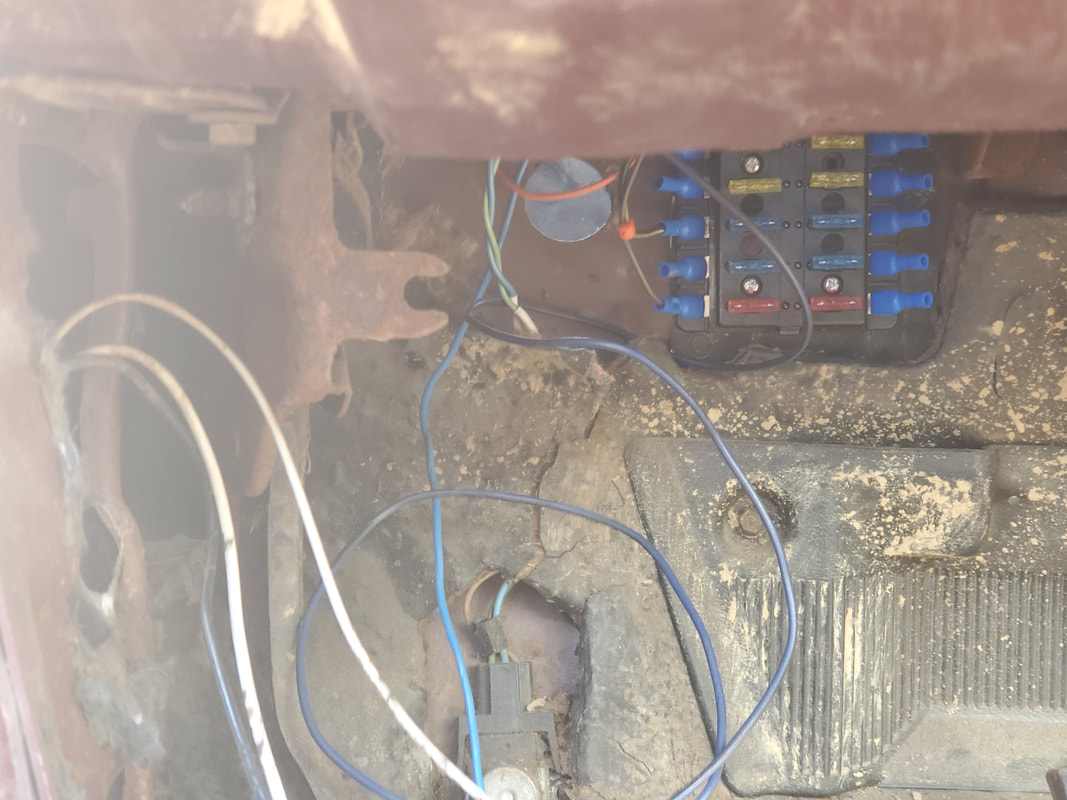
Now it's time for the rewiring. To start things off I had to mount the fuse box in place under the dash. I cut and screwed in place a piece of sheet metal to cover the opening where the old junction block/fuse box was mounted. This provided the surface I needed to secure the fuse box in place. From there I took time to isolate the separate circuits on the different plugs that I have on the gauge cluster, dash frame and steering column, among other things. I have to have the wires separated that will feed power in from the battery to the accessory switch and start switch, as well as the output to the fuse box. The plugs for the headlight and wiper switches on the dash are mapped out, along with the turn signal lights, dash lights, and fuel gauge on the gauge cluster. The HVAC controls only have the plugs for the blower motor and AC clutch engage switch. The clock on the dash, the floor headlight dimmer switch and other individual devices all have their own plugs. As for the turn signal on the steering column, that device, along with the top of the column itself, are broken, most likely from a past theft so I will probably replace the broken switch with a simple SPDT switch to allow for basic switch on/off function for the left and right sets of lights. Lastly I had to reinstall the dash so I can have everything in place in order to get the proper lengths of wire run to prevent excess wire from being piled up behind the dash. I also installed the defroster and chest level vents, further completing the HVAC retrofit.
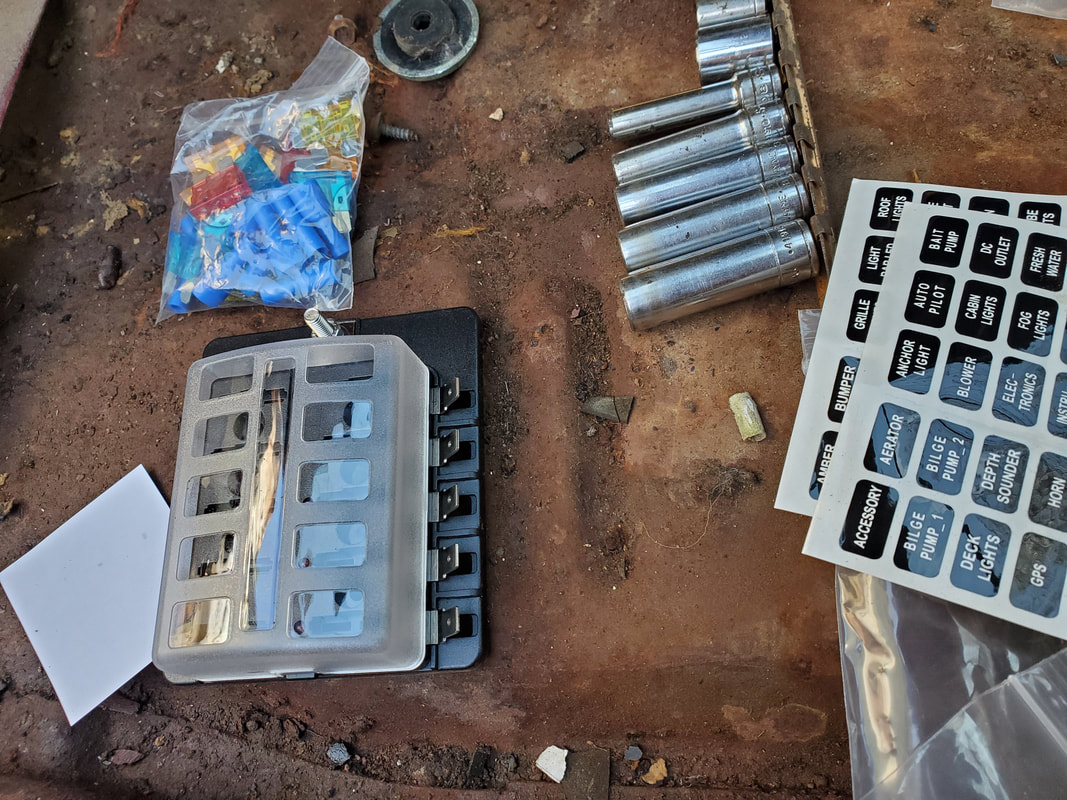
Aftermarket fuse box with identification stickers and pack of fuses/terminals.
Sheet metal patch cut and screwed in place over hole from old fuse box.
Zoomed out shot of sheet metal patch showing the floor dimmer switch with its wires twisted together to keep them together.
Fuse box mounted to sheet metal panel with terminals in place to have them ready for future hookup.
Gauge cluster showing back with printed circuit board and wires that were isolated from the rest. Unused wires were bundled together in electrical tape. Clock plug is separate.
Back of dash frame showing wiper and headlight switches with wires secured/separated. Since the headlights, dash lights, and taillights will be on, I only needed two wires of the plug to allow the headlight switch to be used as a simple on/off switch. The wires for the wiper switch match up to the wires on the wiper motor plug with the exception of a black wire on the switch and a yellow/black wire on the motor plug.
Dash frame mounted in place. Four screws along the top and two lag bolts on the bottom corners hold the dash frame in place.
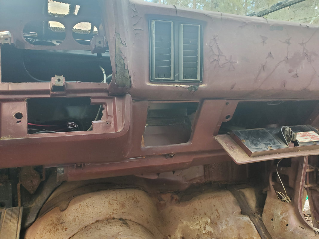
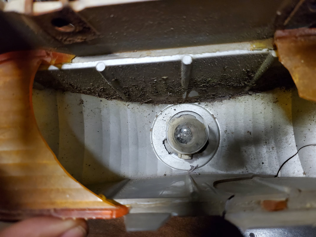
The defroster vent and chest vents were installed first and can be faintly seen behind the dash. I will have to cap off the ends of the chest vent duct since the flexible tubes that feed air to the side vents were rotted away and unusable.
|
|
|
|
|
|
|
|
|
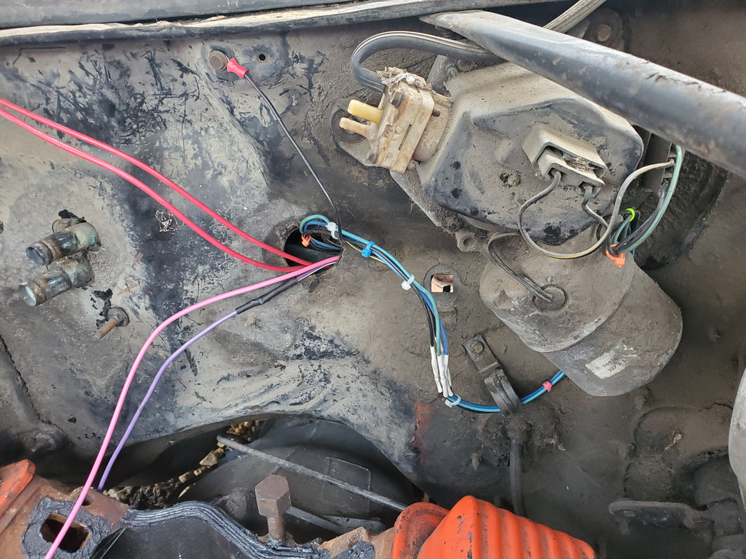
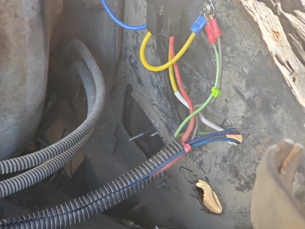
With the preliminaries out of the way, I started off with the closest circuits I could think of, the headlight and wiper circuits. These two switches in the dash were the first thing my eye caught and one of the more difficult circuits to do since they employ multiple wires on the switches as well as the loads. Starting with the wiper circuit I tried to figure out the pinout for the four wire switch, which has an integrated switch for the washer motor. The wiper motor assembly also has four wires on it too. After doing some quick research, which would've saved me some time, I found that the power in actually comes in on the wiper motor, while the switch has three wires going into the motor assembly with the fourth being a ground. I ran all four out through the firewall to the motor and terminated the ground with a terminal on the firewall and hooked the three color coded wires to the wiper motor's plug. The power feed wire was routed back into the cab and hooked up to the fuse box.
With the wiper motor done it was time for the headlight circuit. This was a little more difficult since the newer H4 layout differs from the older layout on these cars. I had to use the 69 Mustang's H4 wiring as a reerence point to get the pinout right for the plugs on the Elco. I isolated two wires from the headlight switch to use it as a simple on/off switch, which I decided to use to switch an automotive relay. The H4 layout uses a single 12v power feed with the high and low beams being on switched grounds, versus switching the 12v power to the high and low beams with a single fixed ground like the old configuration. On this setup I'm going to use a combination of both layouts. The auto relay will have its coil switched on from the headlight switch, getting power from the fuse box with the other terminal hooked up to a ground on the firewall. An inline fuse will be hooked to one side of the switched contacts with the other feeding to the line that will feed 12v power to the light sockets.
The primary light socket will have the 12v switched on via the auto relay, and wired to a constant ground, which was already established on the wiring harness for the headlight circuit. As for the high beam side, this is where the floor mounted switch comes into play. The high beam only light socket will still receive the constant 12v power line but the two grounds for the low and high will be wired together, spliced with the high beam side of the primary light socket then that line, which still requires a switched ground will connect to a line that will connect to one side of the floor switch. The other side of the floor switch will then connect to a chassis ground, giving us our switched ground. This setup allows us to only use one auto relay compared to two like I did in past wirings.
per motor assembly wired up with color coded wires to wiper switch in cab. 12v power is hooked up to the wiper motor and routed back into cab to be hooked up to the fuse box.
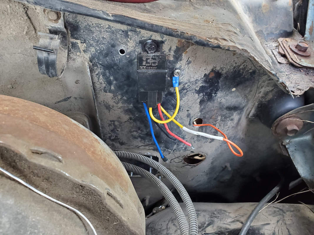
Auto relay used to switch 12v for the low beam side of the headlights. The headlight switch switches fuse box power to the relays coil, which is grounded on the firewall.
Headlight plugs wired in to old wiring harness. Ground was kept for low beam side while high beams were wired to the brown wire in the harness which is connected to the floor switch, which is connected to chassis ground to provide the switched ground for the high beams. The right side light sockets will be a duplicate of this wiring.
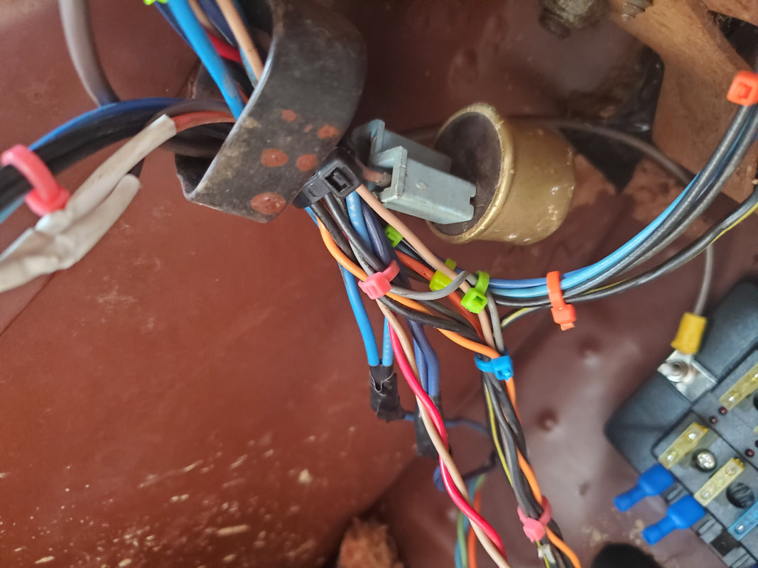
Wire snake saved from old wire harness to contain wires for headlight circuit. Only a couple wires were used from the harness. One or two wires are going to be for the side marker lights, which will be hooked up to the 12v feed for the low beams. The remaining wires will be clipped short to lessen the clutter.
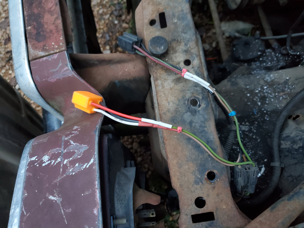
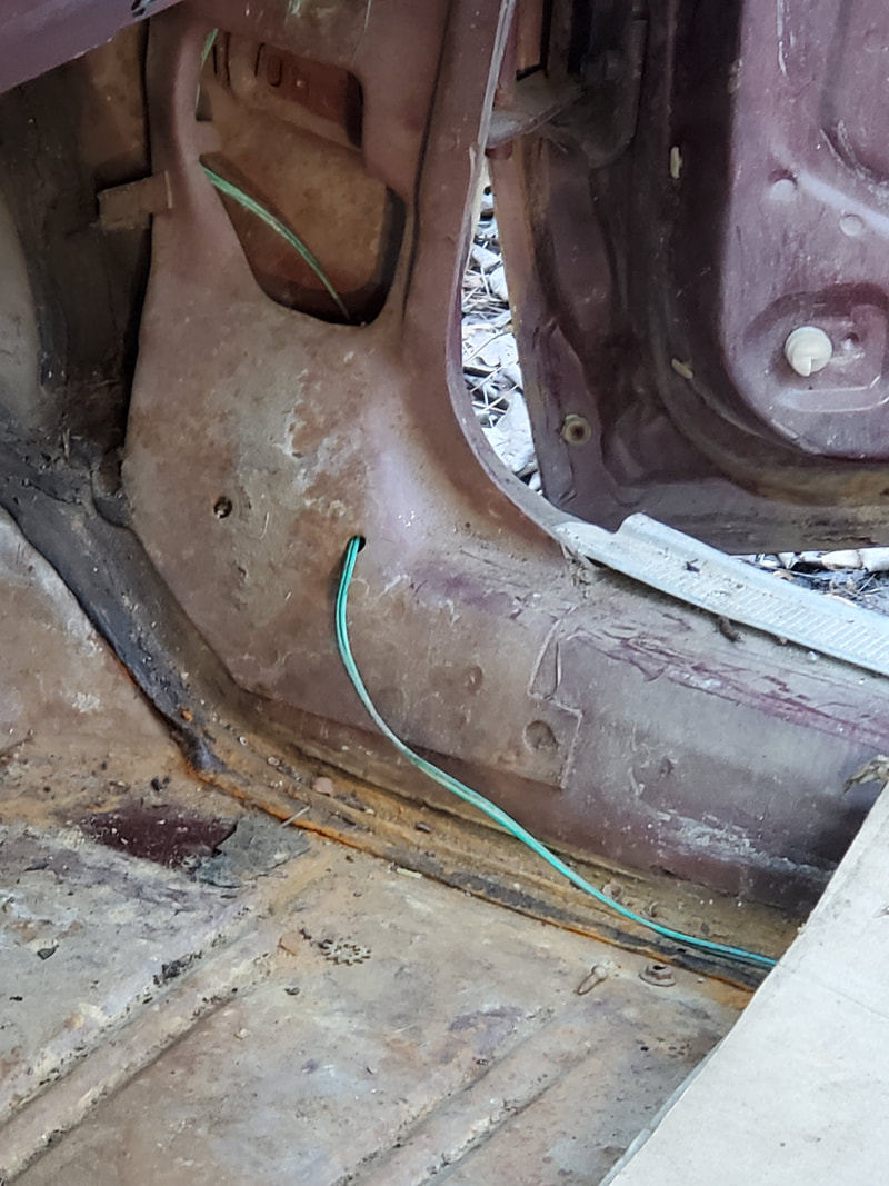
With the left side headlights wired up I moved on and got the right side wired up. On the left side I did have to swap terminals on the primary light socket since I had a mix up with one of the wires and rather than unsolder the wires and redo the heat shrink tubing, I just swapped positions with the terminals in the plug. I had to do the same thing with the primary light socket on the right side so the colors of wires were in the same position on the right side as the left. With the light sockets wired up and secured with zip ties, I addressed the leftover wires in the wire harness. There was a dark and light blue wire and a dark brown wire. I figured these were for the side marker lights, and got that confirmation after checking out the side marker fixtures. I wanted to wire up the side markers to the headlights so they would actually work as side markers but after looking at the turn signal fixture on the left side, I found that it had a blue wire and two brown wires. The fixture was a two filament bulb, with switched grounds apparently. Rather than complicate things trying to wire up the turn signals and the side markers to work independently, I decided to just wire the side markers with the turn signals. It would work out better anyway since the turn signal light fixtures are recessed behind the front bumper. These lights can only be seen directly from the front. The side markers working a signal lights would broadcast the intent to turn to those looking at the car from the side, which is more practical than having side marker lights.
I added the same colors of wire to the wire ends so the two blues can reach into the cab while the brown wire terminates at the firewall, being secured to the firewall with two other grounds via a single screw. As for the two blue wires, enough wire is added to allow for proper routing of these wires along the same path as other wires under the dash, with them to be ran up the steering column to where the turn signal cam is located. Since the old signal cam is trashed, I'll do like I did with the 69 Mustang and add a metal strap holding an SPDT switch mounted on the side of the steering column. This switch will operate in the same way as the original turn signal switch, down for left, up for right.
Right side headlight sockets wires up and secured with zip ties.
Left side marker fixture with light blue wire and brown wire.
Right side marker light fixture with dark blue wire and brown wire. Both sides will be used as turn signals along with the primary turn signal fixtures behind the front bumper.
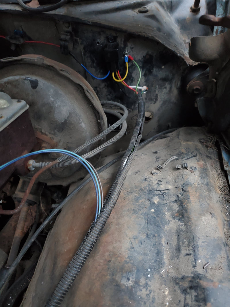
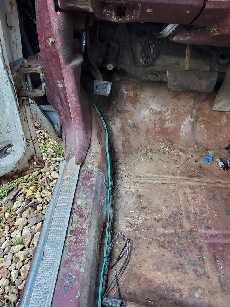
Wire snake with wires bundled up routed to the firewall with the blue wires going through the firewall. Brown wire terminates at the firewall with a grounding screw along with a couple other ground wires.
Blue wires routed under the dash, staged close to steering column for future routing.
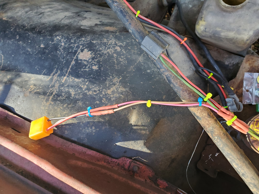
Hooking the gauge cluster lights and turn signal lights is pretty straightforward. The fuel gauge is the only other circuit that will be hooked up since there are idiot lights in place of actual gauges on the gauge cluster. I routed the dash light wires, which includes the ground that everything shares, over to where the headlight circuit wires are. The ground was established on the plate where the fuse box is mounted and the power line for the dash lights was spliced into the wire coming from the headlight switch. As for the turn signals, I added wire to the lines coming from the firewall and routed them up the steering column to terminate where the switch will go. A single power wire was routed back down the column and hooked to a flasher relay then to the fuse box. The two turn signal wires from the gauge cluster were spliced into the main turn signal lines that were already established. Next was the rear lights in the bumper. The bumper has a separate wire harness that plugs up to a plug in the car's body which then feeds another wire harness routed through the car's body up to the cab on the driver's side, which I had to rewrap with fresh electrical tape to cover areas where old tape was able to be peeled away. The cable was routed along factory harness straps under the dash to get the wires close to the fuse box and the loads they'll be hooked up to. The bumper has four lights, on each side there is a single filament socket and a double filament socket. I decided to use the single filament sockets for taillights and the double filaments for brake and turn signals. I spliced both the taillight wires and turn signal wires into the existing circuits or both, then hooked the ground wire up to the same point on the fuse block mounting plate. There was a single wire that was used for a tailgate ajar switch, which will not be used. With that, I can turn my attention to the HVAC, since I can't hook up the fuel gauge since I still need to get the sending unit replaced and the tank reinstalled.
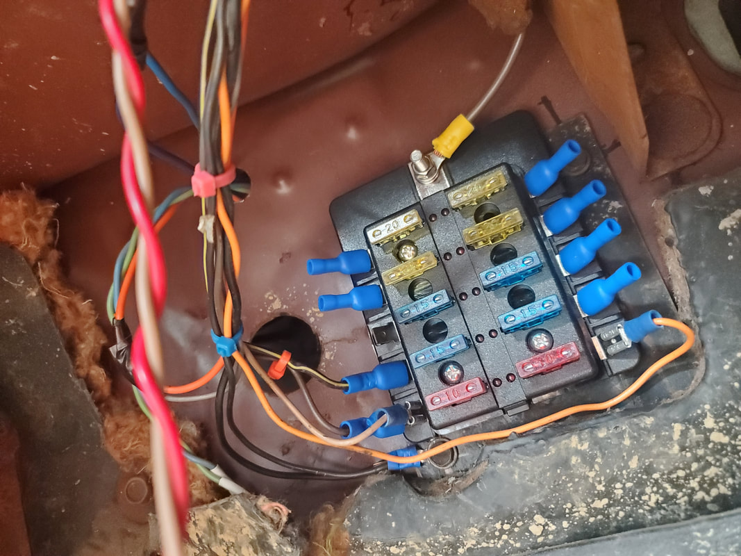
Fuse box with HVAC power, headlight and the clock hooked up.
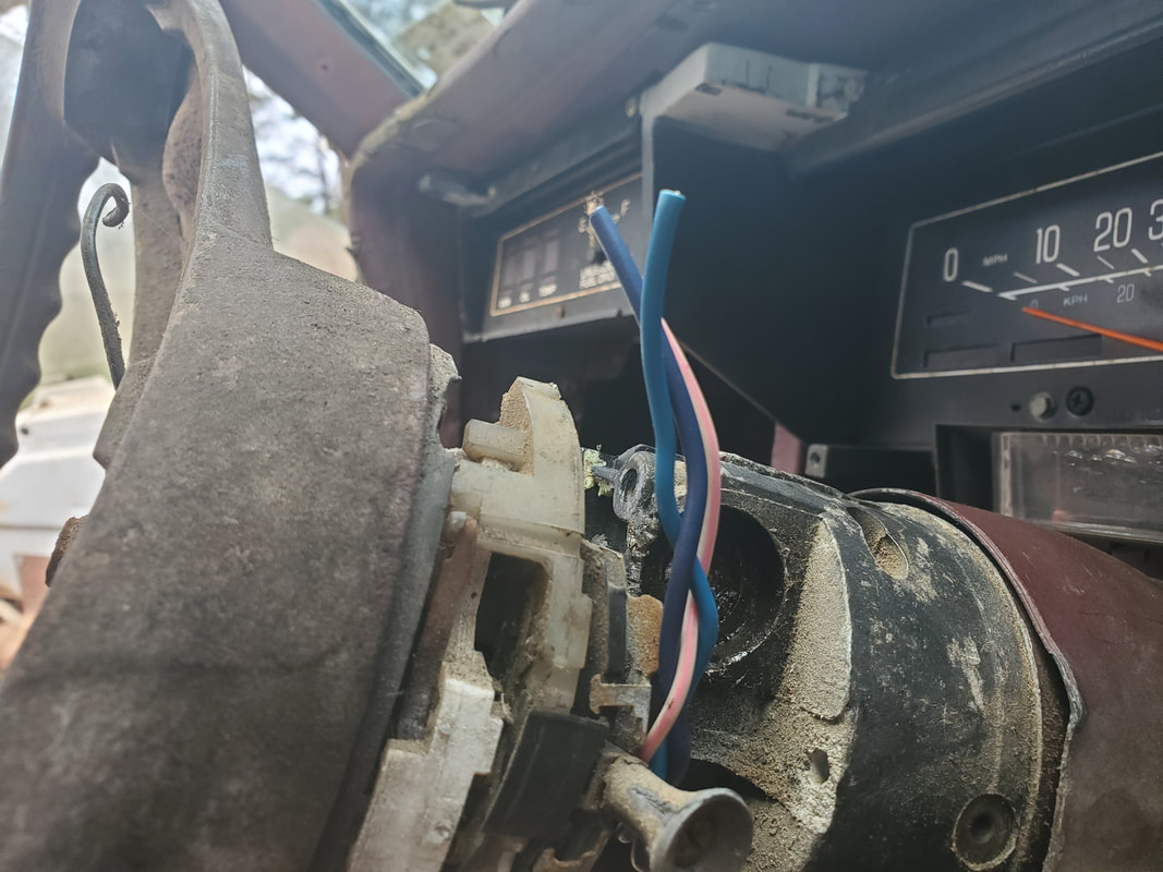
Turn signal wires routed up through the steering column to where the switch for the turn signals will go.
Flasher relay plug wired to turn signal power feed circuit.
Bumper lights with wire harness hooked up.
Close up of plug for wire harness.
Chassis plug for bumper light wire harness.
Wire bundle after rewrapping with fresh electrical tape. It's coming through the left rear of the cab here.
Note wrapped wire bundle how its routed out of the way while still being close to the action.
Bundle of wires with insulation exposed from bundle. These will go between the turn signals, taillights, brake lights, ground and the tailgate ajar switch, which won't be used. The brake light was a simple hook up with a power line from the fuse box to the switch and the other side of the switch going to the line feeding the brake lights.
The next order of business is the HVAC control panel. The vacuum manifold/switch was non functional so I couldn't switch on the blower when the lever is moved from the off position on the panel nor will the AC clutch come on. The solution I came up with to remedy this while still being able to use the control panel in its normal capacity is to mount a couple of micro switches on the body of the control panel so the lever can hit both of them. The micro switches are SPDT switches so there's a normally open and normally closed (NO/NC) contact. The configuration I came up with was to have one switch be an on/off switch but instead use the NC contacts. Power from the fuse box will come in to the common terminal and out from the NC contact, where it branches off, feeding an automotive relay on the firewall and the common contact on the other switch. When in the off position the contacts will be open, not letting power out to the auto relay and other switch. When the lever is moved from the off position the contacts close and power is routed through the relay, which switches power on to the blower relay mounted on the HVAC box, turning the blower on. It also routes power to the contacts on the other switch. When the lever is moved all the way to the right, where the heat selection is, the NO contacts close, and will send power to the auto relay that will control the water valve or the heater core. When the lever is moved from the heat selection, the NC contacts will be closed, sending power to the AC clutch auto relay. Of course this means the lever doesn't have to be on the actual AC selection to have working AC.
With the wiring and the switch layout figured out, I took the old wire harnesses for this circuit and wired everything up. I had to add another plug set with three wires to take into account the added wires from the micro switches. The wire harnesses were for the blower/fan speed control switch and the on/off switch that is no longer present. Either way I wired up the new circuitry from the switches to the resistor pack and blower relay, and hooked up one auto relay for the blower motor circuit. The wires for the heat valve and AC clutch will be left hanging since I need two more auto relays. With everything wired up, I reinstalled the control panel and zip tied the wires to neaten them up. I also took time to wire up the power lines coming from the battery going to the blower and auto relay since these high wattage lines weren't hooked up yet. I also got the ground cable and wire hooked up with the intent of putting power on the fledgling electrical system to test things out. I found the wiper circuit worked perfectly, even the homing feature worked where the wiper arms return home. As for the blower motor, while everything worked as designed regarding the micro switches, I didn't have speed control. I'll have to look at everything to see why I don't have speed control. As funny as it sounds even with the blower running at full speed, the air flow was reasonable but not insane. I could've ended up just omitting the speed control switch all together if I was really trying to go simplistic and just have the two micro switches control everything, with the lever automatically turning the blower motor on high and controlling the heater valve and AC clutch. If I can't get the resistor pack and switch assembly I'll have to figure out another alternative, like a rheostat speed control or something on the order of that, maybe a two position switch that just switches between high and low, like I did the wiper switch on the Dodge.
HVAC control panel with old wire harness and defunct vacuum manifold/switch assembly.
Wire harness wired up and ready for hooking up to the other hardware in the HVAC circuit.
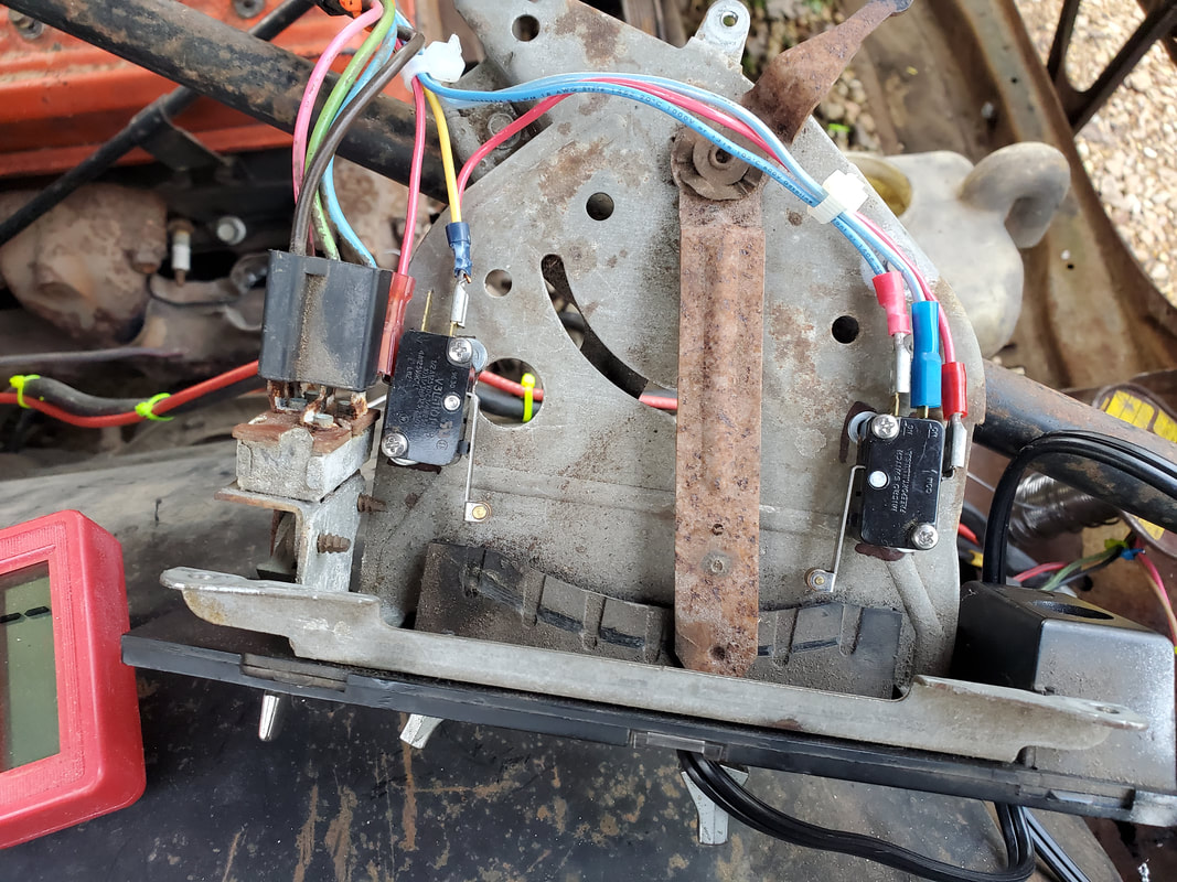
HVAC control panel with micro switches installed and wired up. Note their position relative to the ends of the sweep of the lever.
Wiring going to blower resistor cluster and relay, secured with zip ties.
Extra plug added to accommodate the wires from the micro switches.
HVAC control panel installed in dash.
Wiring under dash zip tied together from control panel going through firewall.
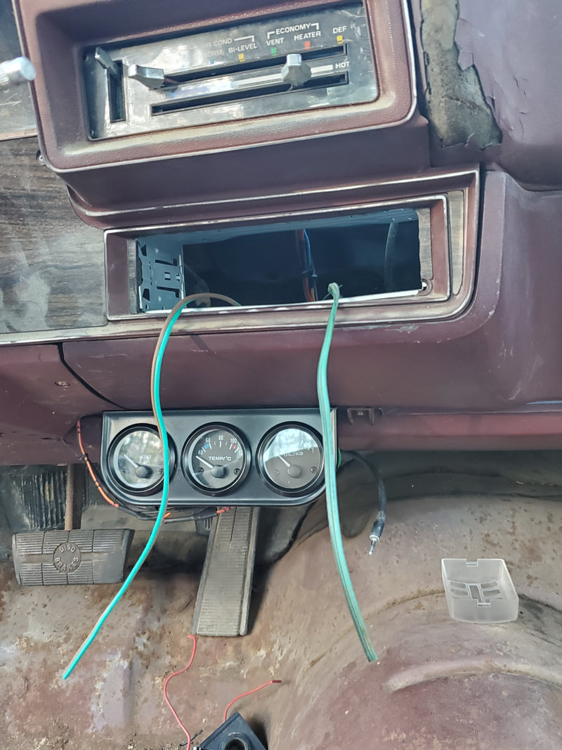
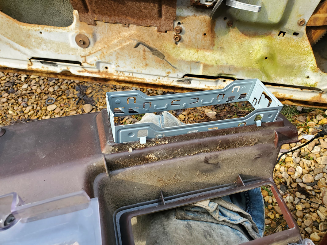
Next I started to install the single DIN radio mount. I had to trim out the plastic from where the old radio went to open it up since the old radio had slots for the knobs and the display. After cutting out the opening on the dash and the dash trim panel I installed the radio mount. I then diverted and installed the other half of the lower duct assembly for the chest level vent portion of the HVAC system. I just wanted to get these parts out of the way and see where I would be able to route wires as I advance deeper in the job. I had to cap off the ends of the lower ductwork and the only thing I found that would work was a large mason jar lid and ring. I used these on both ends, hot gluing them in place. Now the air can only move through the chest level vent and the two small vents below the dash. Next I moved to the aftermarket gauge cluster. I started off by making a mini wire harness for the gauges before hanging the assembly, so I won't have to be on my back trying to install each wire in that awkward position. I hooked up the grounds for the gauge lights and the gauges themselves together and routed the wire around to the fuse box to hook it up to the ground bolt. The power wire for the gauges and voltmeter were connected to one another and routed over to the fuse box as well, being hooked to a fuse terminal. The gauge light power wire was routed around to the line coming from the headlight switch, being soldered in place and taped up. With the wires hooked up all that's left are the two wires for the oil pressure sensor and temperature sensors on the engine.
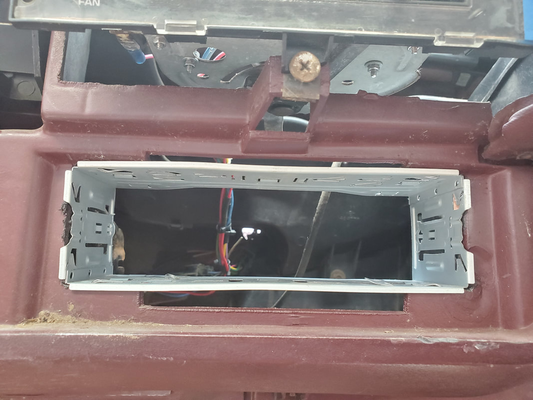
Single DIN radio mount secured in place in newly cut out hole in dash.
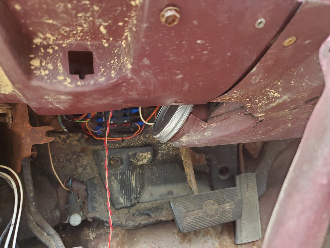
Left side lower duct/vent with mason jar lid and ring glued in place over opening on duct.
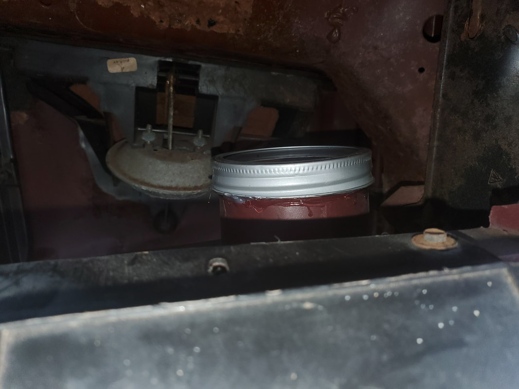
Right side duct with jar lid and ring in place.
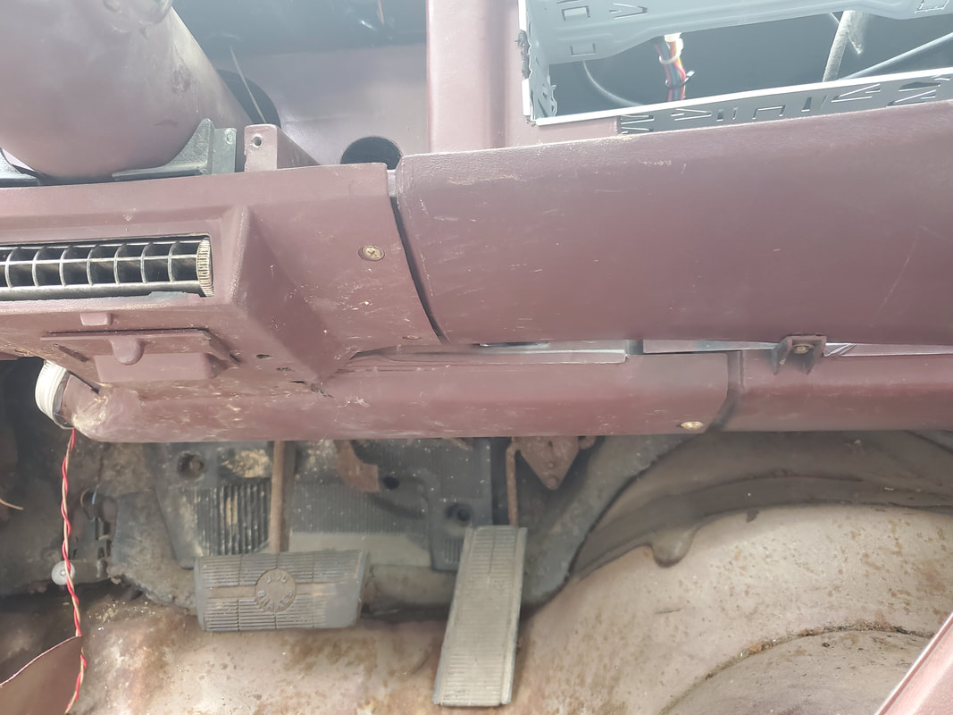
Lower vent duct assembly for left side secured in place under dash.
Dash/gauge panel trim panel secured in place.
Coseup of trim panel where it was cut out to accommodate the radio mount.
Power wires for aftermarket gauge cluster wired together to a common power wire going back ot the fuse box.
Back of gauge cluster with all wires in place except the sensor wires for the temp and oil gauges.
Gauge cluster mounted under dash on driver's side.
Sensor lines hooked up to gauges and routed along same lines as the rest of the wires from the gauge cluster.
Wires for the engine control part of the circuit. This includes the sensor wires as well as a line for the starter solenoid and distributor power.
After getting the gauge cluster done, I took a moment to get the power line for the fuel pump hooked up. This was routed up to the engine bay from the fuel pump and through the firewall. Enough wire was used to allow me to route the wire along the same paths as the rest of the wires and still be able to get to the fuse box. With that, the next area of focus is the door switches for the dome light. These switches have three wires, with two being a shared terminal. I only need one of these wires since we're only going to have a single dome light in the car. Even though these switches are two wire switches unlike the later single wire switches that make them a switched ground, I still wanted to use these switches in the same manner. I hooked a terminal to one wire and connected it to a bolt on the metal part of the dash to establish the ground for each switch. the other wire on one switch will be routed over to the 2nd switch then a wire will be run up the A pillar and over to the dome light. A power line will be routed from the dome light back down the A pillar and over to the fuse box, completing that circuit. I also took the time to get the interior panels installed that covered up the area where the switches are, since my work is done. I have enough wire exposed to connect to even with the panel in place. This will also take these two pieces out of the equation since I will be working on installing the interior pieces after the rewiring job is done.
Wires from switch, ground is hooked up to frame mount and white wire will be hooked up to a line feeding the dome light.
Interior panel installed over opening where door switch and wires are located.
Extra screw added to extension on the panel to hold it in place so it's not flopping around within the door jamb. Tacky, yes, effective, yes.
We picked up a dome light from the junkyard that was the same as the one in the 69 Mustang, AKA The Rustang. This light fixture came from a late model Grand Prix and has a mount with rare earth magnets in it so the fixture can stick to the metal ceiling like glue. I also decided to use a couple of light fixtures I pulled from the car that were mounted under the dash. I mounted the two lights at points that appeared to be sufficient based on how the fixtures are made. The wire from the passenger side light is routed over to the driver's side and spliced in then the power line is run from the fuse box to the splice point. The light fixtures' other wires connect to the door switches to then go to ground. The dome light already had a pair of wires run so it was just a matter of hooking into this pair to establish a connection for the dome light. Zip ties secure everything nice and neat.
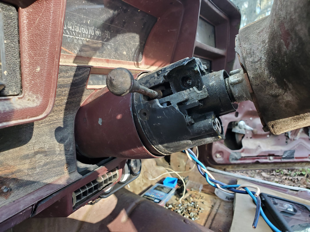
The next thing to be installed was the SPDT switch that will serve as the turn signal switch. Just like n the Rustang, this switch needs a metal bracket or mount to hold it in place. I took a wood framing brace and trimmed it to fit to the lower left of the steering column about where the old turn signal lever was. I had already pulle dthe old turn signal cam and wiring out to clean up the steering column so after making some fine-tuning cuts and grinds on the bracket, I was able to install the switch and wire it up as intended.
From there were the speakers. Also sourced from a junkyard Ford Ranger, these speakers have mounting plates with tabs that made installation convenient. While the speaker magnets hold the speakers in place two o the tabs are used to secure the speakers to the raised portion of the back panel via drilled holes. I still have the mounts and the old speakers so one day I will get the same sized speakers to replace the bad ones that were in this car so I can have speakers in place that are covered by the interior panels. Until then we will be using these junkyard speakers. As for the wires I dug out a couple pairs of two conductor cable and spliced them to the speakers' wires then routed the cables along the corners of the back of the cab, down to the floor and to the front. From here the cables go up and under the dash, routed alongside the other wires, terminating at the radio hole. Once we get a radio in, the speaker wires will be all ready to go.
Driver's side under dash light fixture secured in place.
Passenger side under dash light fixture in place. One wire goes to the door switches, which are grounded already and the other wire on the light is routed under the dash (along with the passenger side door switch wire) over to the driver's side door switch and light fixture where all is spliced together. A single power line from the fuse box feeds the under-dash lights and the dome light, which is also spliced with the under dash lights..
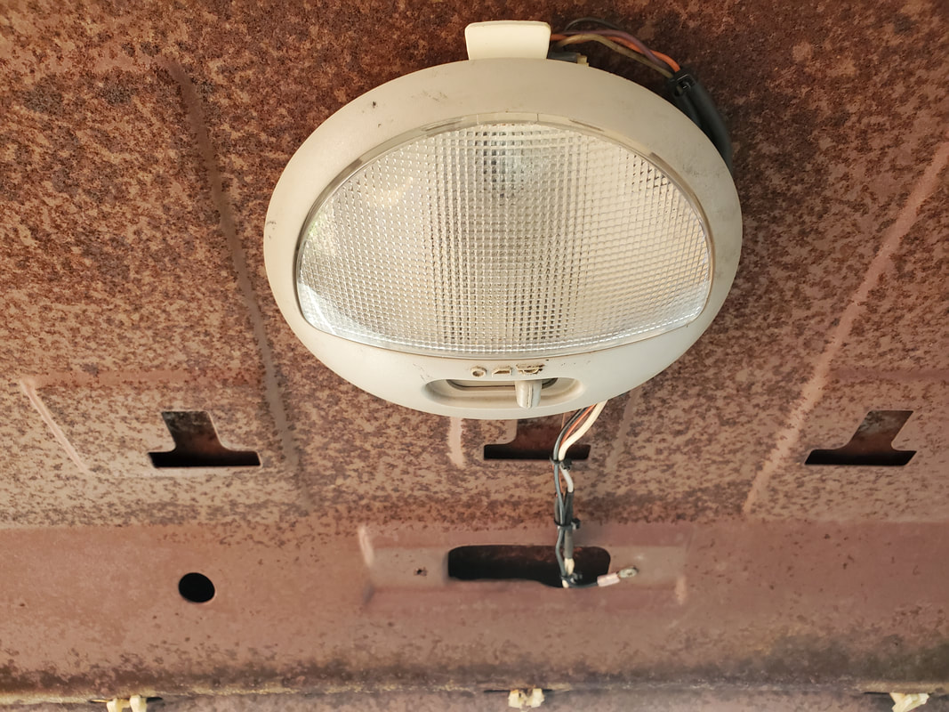
The Grand Prix dome light, wired up, and hung in place via the rare earth magnets in the fixture.
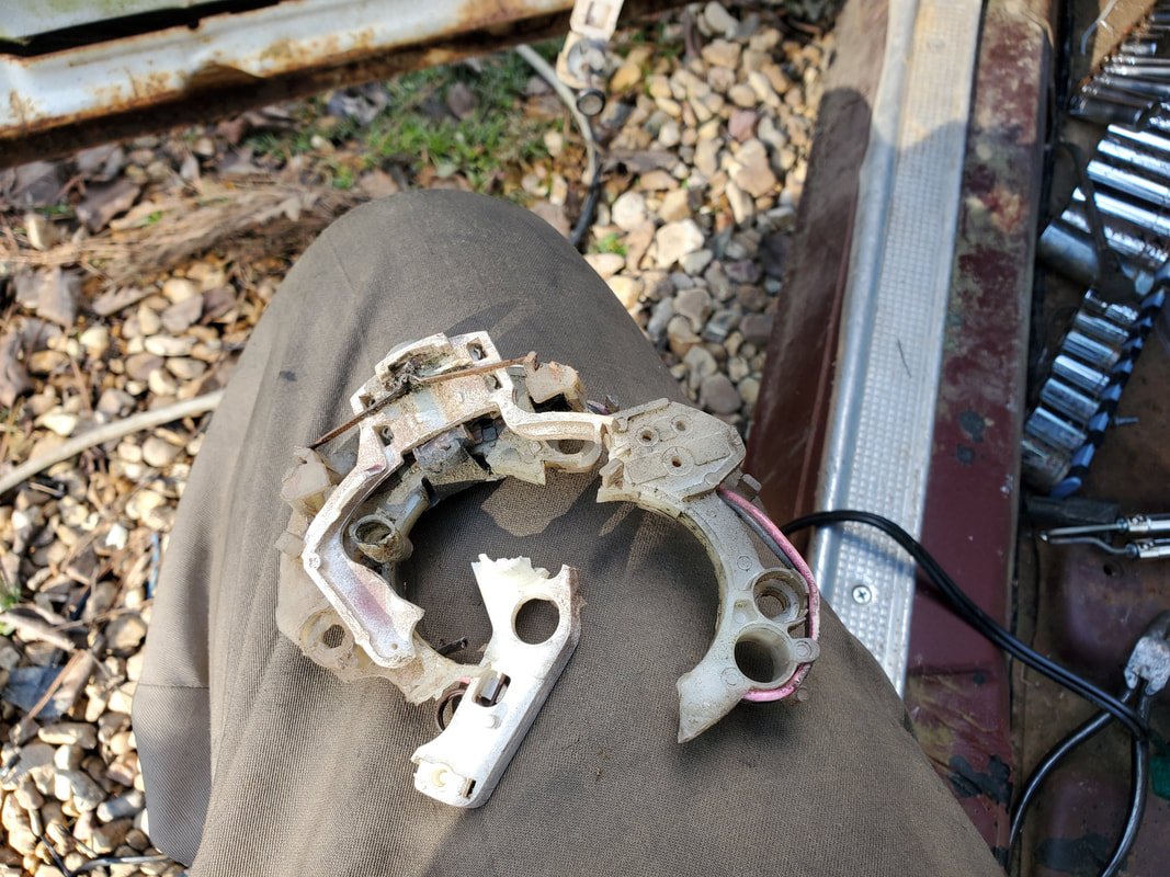
The old turn signal cam removed from the steering column.
The steering column ater removing everything, its nice and open now.
Wood frame bracket trimmed and shaped to fit on steering column to hold the SPDT switch that will serve as the turn signal switch.
Side view of bracket showing extra hole on the side of column body and secured with a self tapping screw.
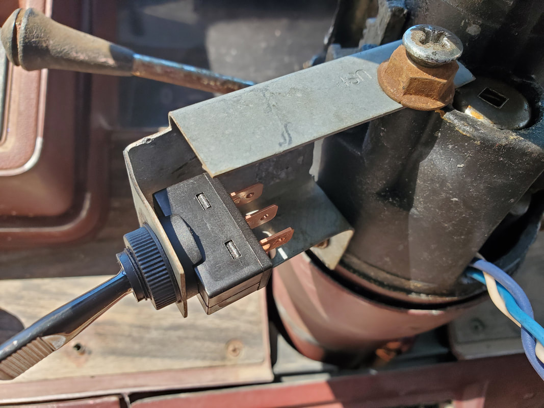
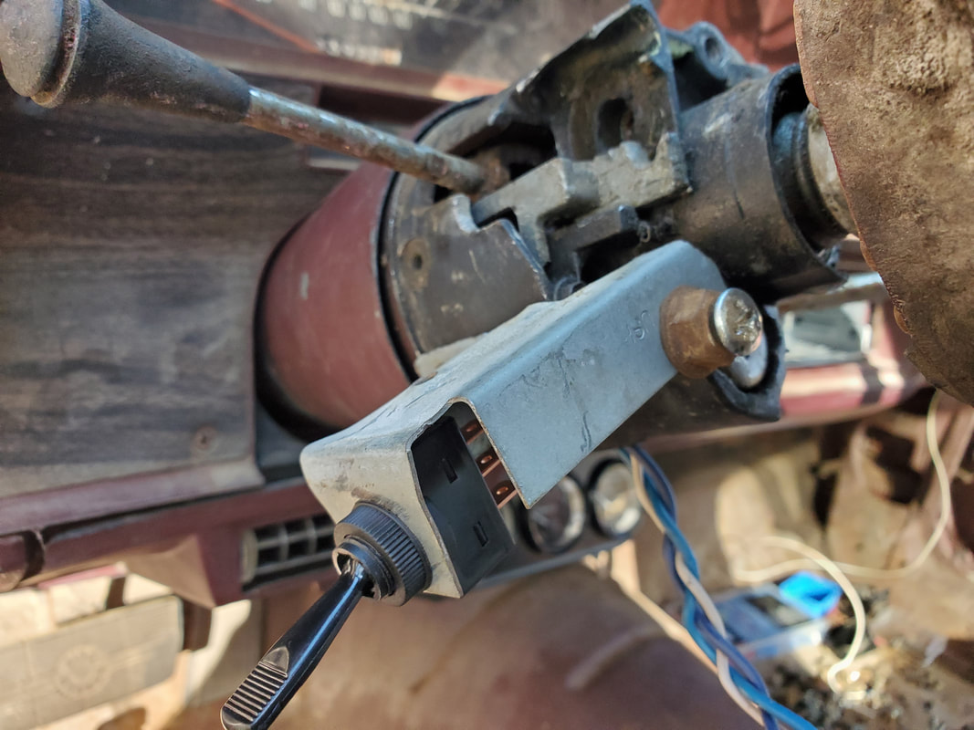
View of switch showing how its in place on bracket.
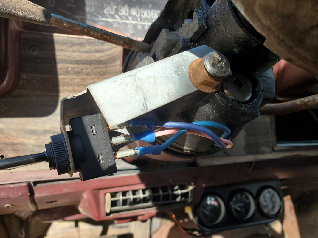
Switch wired up with wires that were already in place from previous work.
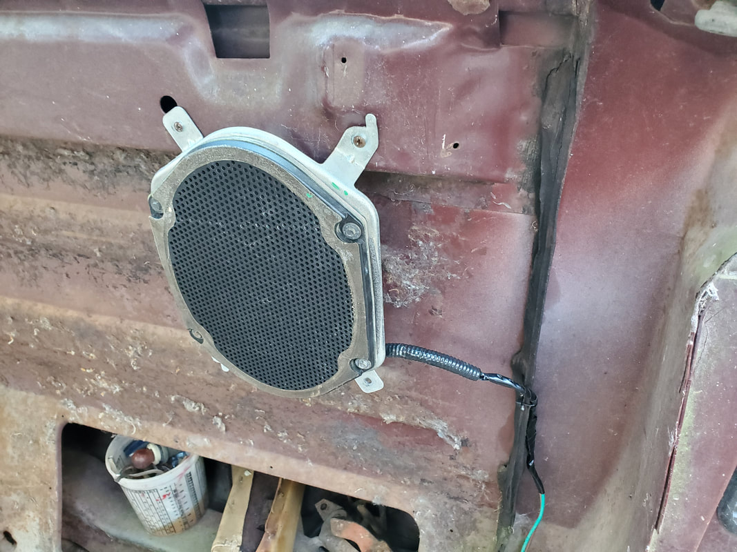
Driver's side speaker in place. Note two mounting tabs holding speaker up to raised portion of back panel. Also note the wiring secured to a hole drilled on body seam.
Passenger side speaker follows the same pattern as the driver's side.
After running the passenger side speaker's wire pair down and along the floor/rocker panel, it's routed through an already existing hole and up to where it runs parallel to the door switch/under dash light wiring under the dash.
Speaker cable routed up under the dash and secured with zip ties to taillight wire harness.
Both pairs of wire in place at radio hole and on opposite sides to designate which side is which for when we install the radio.
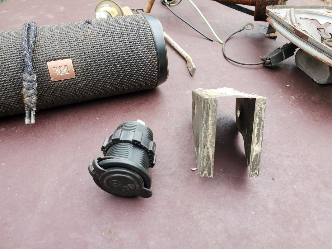
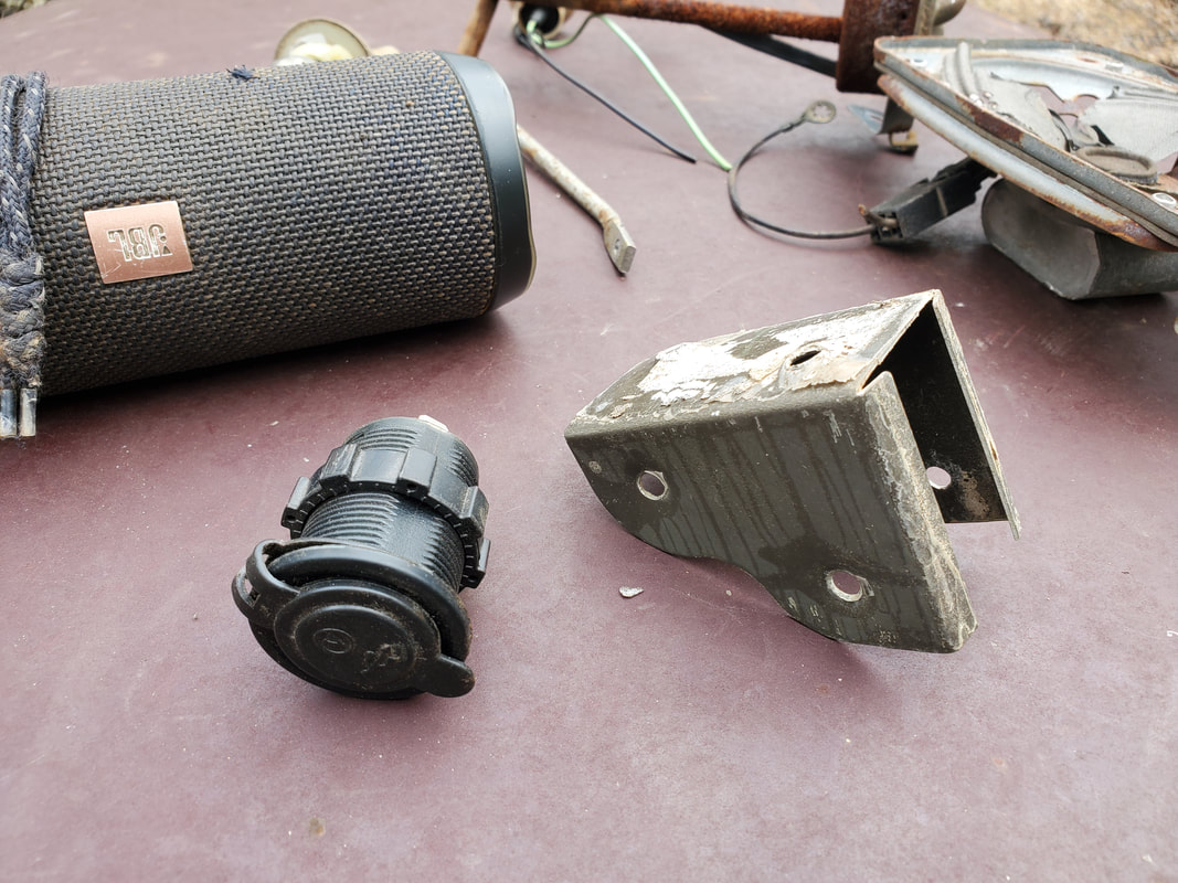
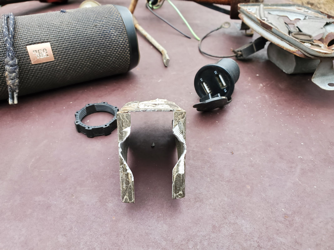
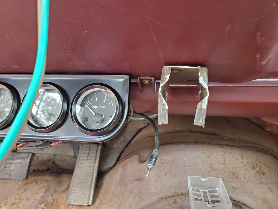
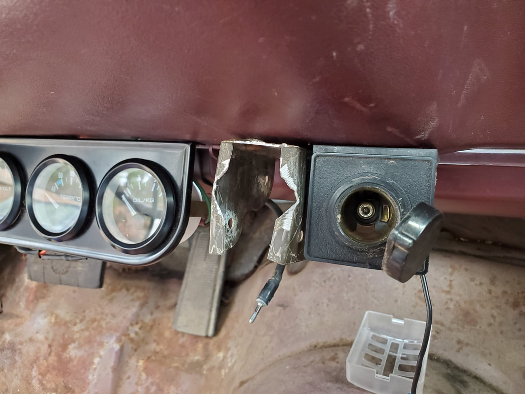
The next couple of things to install are a pair of 12v receptacles and the replacement taillight sockets. Starting with the 12v receptacles, I had two that I salved from an old project. Unfortunately, one of them was partially melted so it was useless. The next solution was to install a dedicated USB receptacle in place of this 2nd 12v receptacle. This USB receptacle is a flush mount unit that would go in a hole in the dash but because no more holes would be put in the dash, I had to figure out another solution to this problem. That solution would be in the use of another wood frame bracket like with the turn signal switch. To facilitate this install I trimmed out the sides to open up the mouth to accommodate the round body of the receptacle. After mounting the bracket, I put the receptacle in and used a long bolt and nut to clamp the sides of the bracket tighter, courtesy of the existing holes on the bracket. The 12v receptacle was mounted next to the USB receptacle under the dash as well. Both receptacles were wired together with the ground secured to a chassis ground under the dash and the power line routed through the firewall to the battery. An inline fuse will be wired in to supply constant power to both of these receptacles even with the accessory switch off. I also took a moment to connect the power wire for the interior lights to this same power feed so all three of these loads will feed from the battery to power everything outside of the switched fuse box.
With the work inside done, I moved to the taillights. I had two pairs of light sockets salvaged from late model cars, two slightly different styles but they use the same newer bulb. I just had to determine the pinout for the low and high lumen filaments so I can wire the low lumen filament on the taillight circuit and the high lumen on the brake light circuit. The turn signal is a standalone circuit so both filaments were wired together. I also had to whittle away some of the taillight housing to accommodate the newer light socket since only one pair was able to fit as is. The opposite side to the hole that I had to whittle out was degraded enough with missing plastic that I was able to twist lock the socket in with little resistance. With the sockets all wired into the bumper wire harness, we're just about ready to start testing things out.
The USB receptacle and wood frame bracket to be installed under the dash.
A side angle shot of the wood frame bracket to show what we're working with.
Wood frame bracket with sides whittled out to accommodate the round body of the receptacle. The angle grinder helped me along on this work.
Modified wood frame bracket secured under the dash via two drilled holes and some sheet metal screws.
12v receptacle installed next to USB receptacle the same as the wood frame brace.
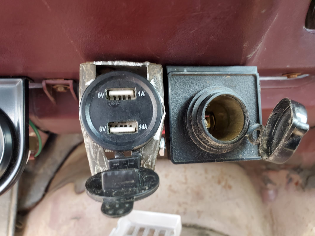
USB receptacle secured in the jaws of the wood frame bracket.
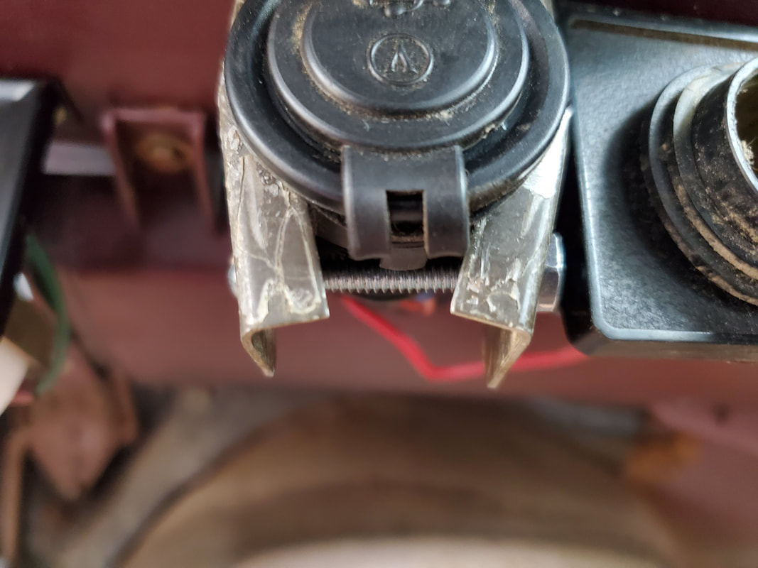
Closeup of the nut and screw tightening the sides against the USB receptacle body.
Replacement taillight sockets installed in light fixtures and wired into the bumper wire harness.
Closeup of the two different styles of light sockets installed in the light housing. The inner mount had to be whittled away with the battery rotary tool to open the hole to allow for easy twist locking of the socket in the hole.
|
|
|
|
|
|
|
|
|
|
|
|
|
|
|
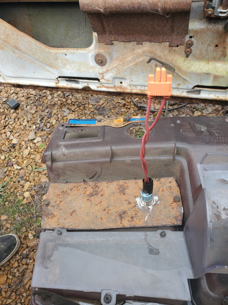
Getting more into the home stretch of the rewiring job, there were a couple of things that I put off. One of them is the small reading light that mounts over the rear view mirror. This light is held in place via two screws, which also provides chassis ground and has a single power wire routed along the top of the windshield to the driver's side A-pillar and down into the dash. I don't have the trim piece for the top of the windshield but I do have the A-pillar. This piece is degraded enough that the plastic is breaking away very easily. I did add another screw to hold the piece in since the top piece isn't there to hold the top of the A-pillar piece down. Hopefully I can find another set of trim pieces to replace these so I can put things back together better but until then, this will have to work. The power wire was routed down and into the fuse box, to only power the light when the accessory switch is on.
The next thing is the horn. I have some horn assemblies that were salvaged from other cars we stripped plus a horn switch that was pulled from the old Tracker after it was crushed by a tree. Since the steering column is too trashed to be able to use the horn button, I had to add this button to the dash somehow without drilling any more holes in the dash panel. Since the HVAC system was downsized, there was a vent on the far left of the dash panel that was not being used. After removing this panel I replaced it with a piece of sheet metal and drilled a hole in that to install the horn switch. The wires on the horn switch were hooked up to one side of a male/female plug coupling, with the other side feeding a wire down to the fuse box and the other feeding a wire out through the firewall and into the same snake carrying the headlight wiring, over to the driver's side headlight area where I planned on mounting the horn. The horn uses a chassis ground so that one wire feeding the horn is all that's needed.
The next thing is the horn. I have some horn assemblies that were salvaged from other cars we stripped plus a horn switch that was pulled from the old Tracker after it was crushed by a tree. Since the steering column is too trashed to be able to use the horn button, I had to add this button to the dash somehow without drilling any more holes in the dash panel. Since the HVAC system was downsized, there was a vent on the far left of the dash panel that was not being used. After removing this panel I replaced it with a piece of sheet metal and drilled a hole in that to install the horn switch. The wires on the horn switch were hooked up to one side of a male/female plug coupling, with the other side feeding a wire down to the fuse box and the other feeding a wire out through the firewall and into the same snake carrying the headlight wiring, over to the driver's side headlight area where I planned on mounting the horn. The horn uses a chassis ground so that one wire feeding the horn is all that's needed.
Overhead reading light mounted over area where rear view mirror goes. Note single power wire routed along top of windshield going left towards A-pillar.
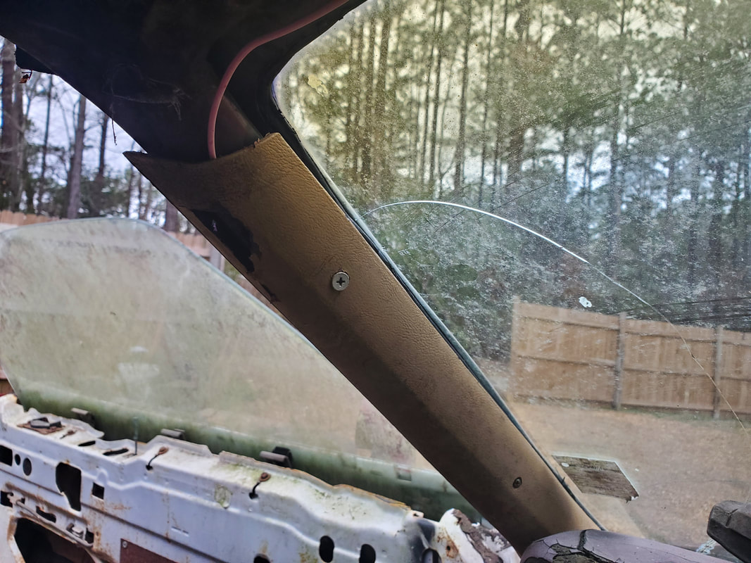
A-pillar molding installed. note extra screw used to secure trim piece in place due to missing trim piece along the top that would've otherwise held the top of the A-pillar trim. Also note the power wire routed down and behind trim piece to hold it in place as the wire goes down into the dash.
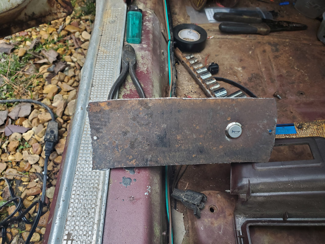
Sheet metal piece cut to fit behind opening vacated by vent piece. Horn switch is installed in hole drilled with step bit.
Back of sheet metal panel with nut holding horn button in place. Note pair of wires terminating on male side of plug set.
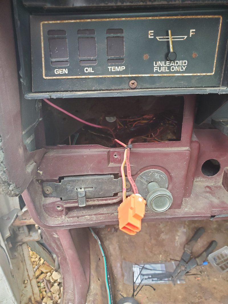
Female side of plug set, connected to wires going to fuse box and out through firewall to horn.
Sheet metal panel in dash panel with horn button. Dash panel is installed back on dash, note the extra space on panel for extra switches for other devices.
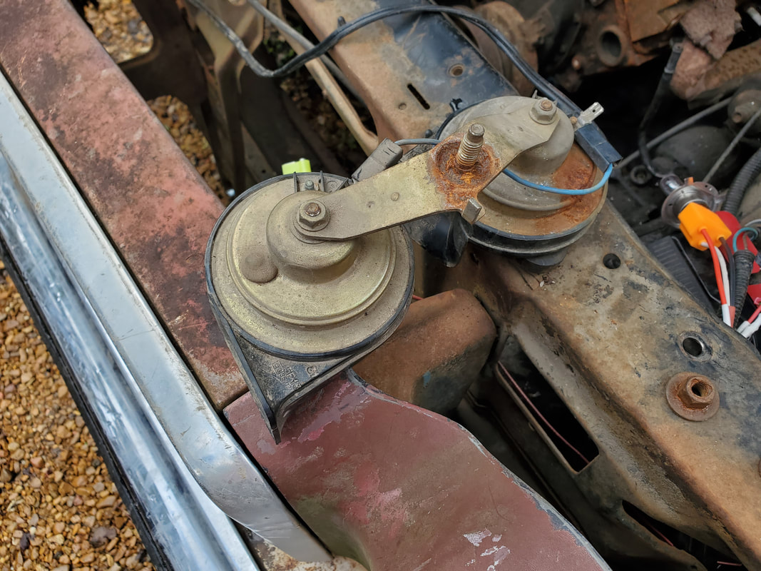
Horn set to be installed just behind the grille.
Horn set installed with single power wire hooked up. Horn system is done!
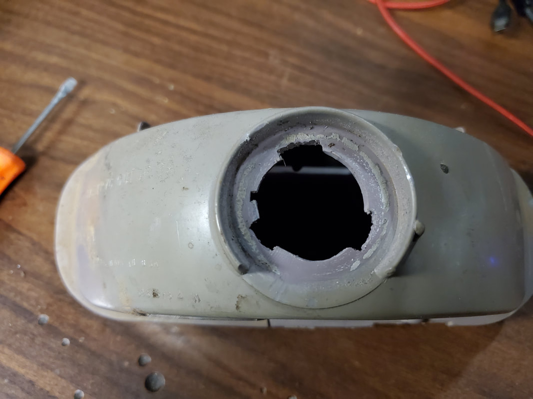
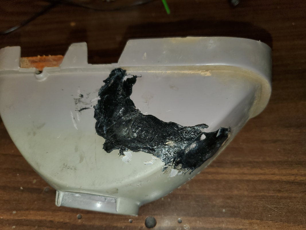
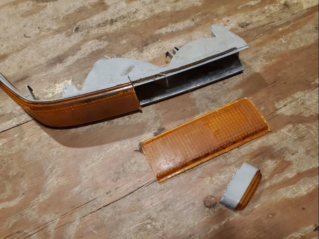
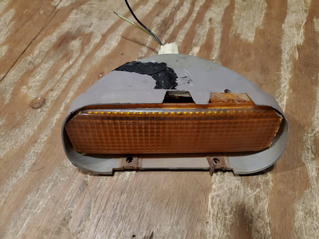
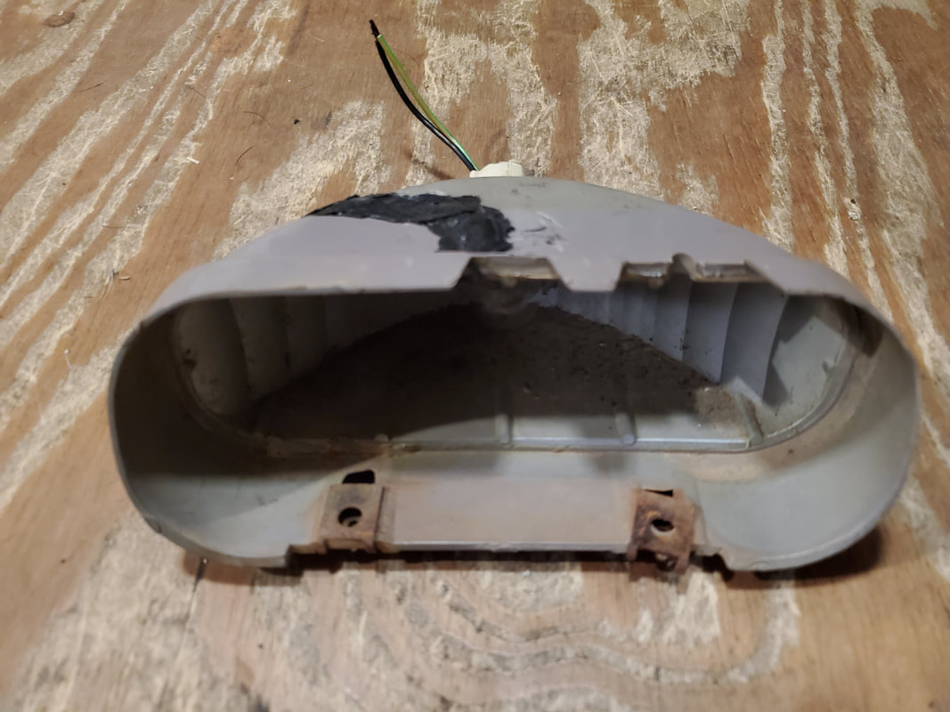
A little aside I decided to do was address the idea that I needed a right turn signal light housing. The old unit is cracked, and the amber lens is broken on the piece, so for all intents this thing needs to be replaced. OR we improvise as our namesake goes and fix this one to be able to get a unit back in the game. I need to also replace the light socket that would go in the housing since that was missing as well. Conveniently I have an extra light socket, salvaged from the rear bumper lights after I changed those around to the newer light sockets. Only problem is I would have to ream out the socket opening on the light housing first. That's where the rotary tool came into play.
I ground the opening enough and ground off an extra tab on the light socket itself to allow me to twist lock the socket into the housing. Once that was done, I used a plastic welding iron kit to repair the cracked housing. The kit comes with some plastic filler sticks that are melted on the iron and mashed into the crack to fill it in and also allow for the plastic to be pressed together to facilitate the repair. Using this hardware, I filled in the crack both inside and outside the housing, even using the iron to melt some of the housing plastic to further "weld" the crack up. After everything dried, the housing was nice and solid. Next is the lens.
Since the old lens was glued in there would be no replacement lens that fits on this housing. My next option was to find another signal light housing that is large enough to allow me to cut out the amber lens and make the cut-out piece fit in our housing. This is the option we went with. I had a spare S10 signal light housing, on top of the pair I already had so it would not be missed. I used the rotary tool to start the cutting out of the section of the amber lens I would need. I ended up using the recip-saw with a fine-tooth blade to cut the end of the light housing off so I can cut along the seam of the lens, which then caused the rest of the lens to pop free. From there I used the rotary tool to trim the corners to allow the lens piece to fit in the housing. Once I had the lens piece fitting properly, I broke out the remaining pieces of the old lens from the housing. I then applied a bead of hot glue around the edges of the housing and pressed the new lens piece in. I finished up with a thick outer bead around the edges of the lens to further seal things up so the lens is in place solidly. With that, the signal housing is ready to be reinstalled behind the bumper and wired in, finishing up the turn signal system.
Light socket hole after reaming out with rotary tool in order to accommodate new light socket.
Light socket twist locked into light housing after reaming out the opening.
Light socket in housing. A foam rubber gasket seals the socket from water intrusion.
Plastic melted along crack with iron.
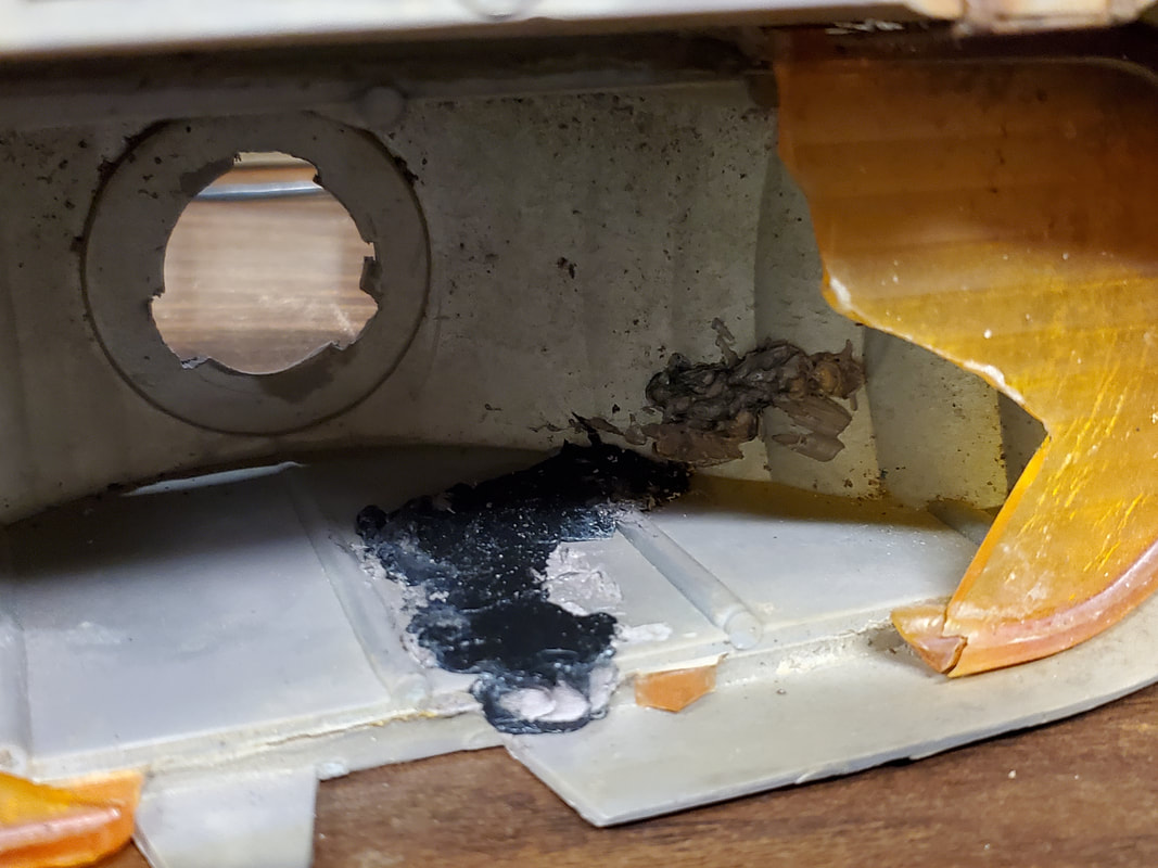
Inside of housing showing plastic melted in crack to further seal and glue crack up.
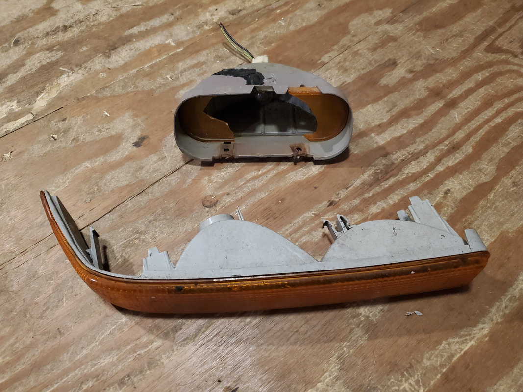
S10 turn signal housing that will give up its life so the Elco housing can live on.
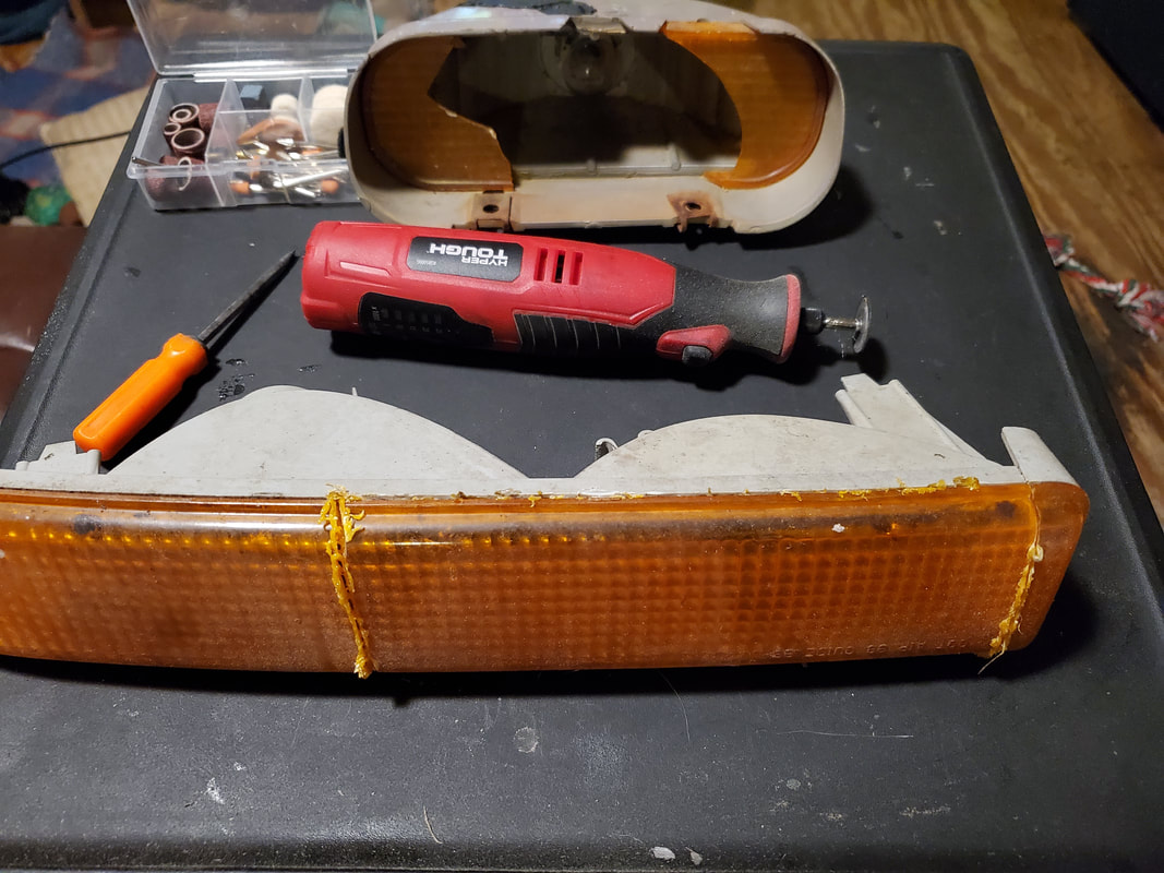
Cuts made in amber lens to start the removal process of just this piece for our new lens.
Piece of amber lens removed after using rotary tool and saw to cut the housing to allow for the piece's removal.
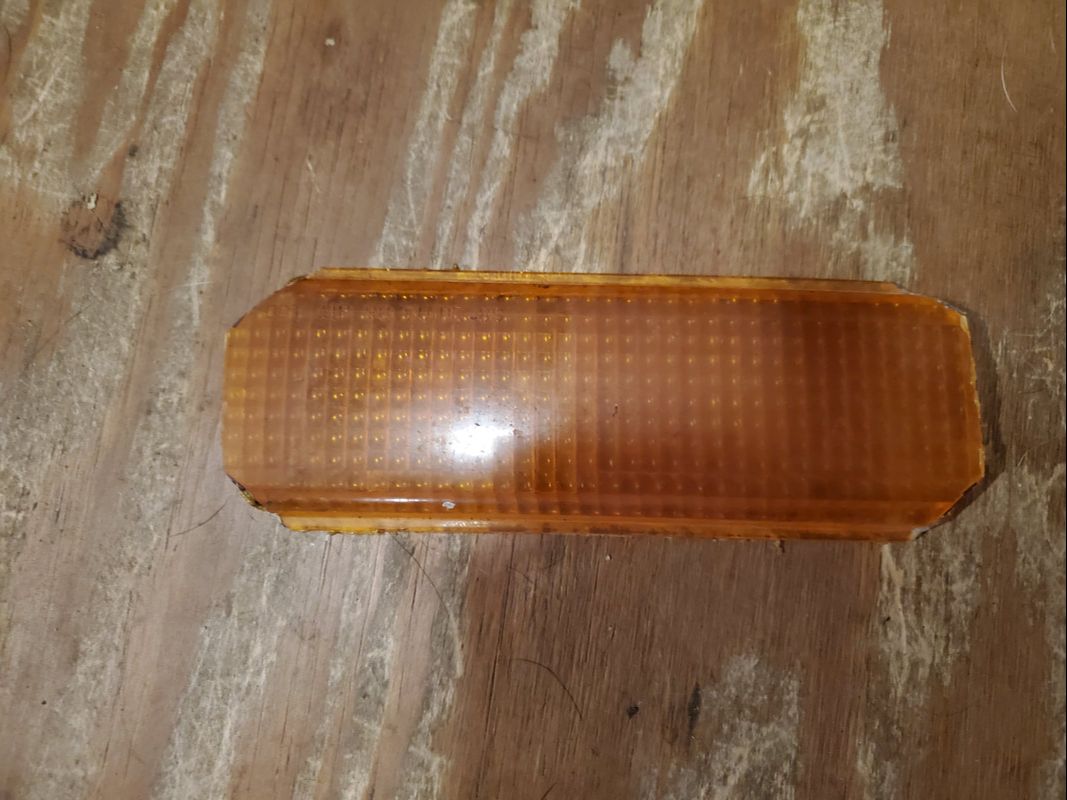
Lens piece after trimming corners to fit the piece inside the housing.
Test fitting the lens in the housing.
Hosuing after removing the remnants of the old lens.
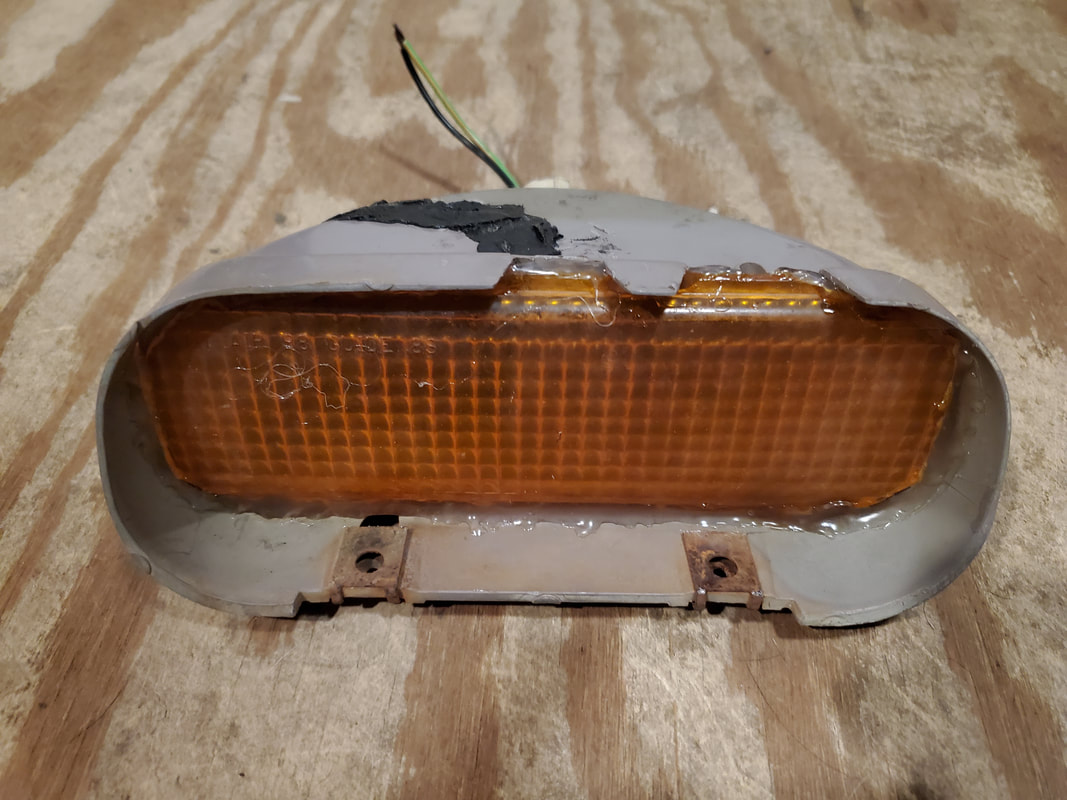
Replacement amber lens glued into Elco housing after making all the necessary repairs.
With our turn signal light done, the next step is the installation. After mounting the piece in place with a couple of sheet metal screws, I spliced the wires into the wire ends to get the light socket in, so the light is ready to go, completing the turn signal system on the car. Next on the menu is the radio. I picked up a media player radio, which has a lower profile body due to its not having a CD player or any other extra electronics. It's literally a dinky MP3 player in a large box made to run off 12v. To wire it in I just need to wire in the constant 12v power and switched 12v power and the two speakers I previously installed. There won't be four speakers or any external loads like power antennae or amplifiers that would require me to use the power on signal wire on the wire harness. After splicing in the speakers, I tapped into the constant 12v power line feeding the 12v receptacles and run a switched 12v line over to the fuse box. I was able to use a twisted pair of red and yellow wire, since the wires for the 12v lines are also red and yellow. With the wire harness in, the next thing ws mounting the radio.
The problem here was the idea that the mount shell I installed in the dash frame is too big to accommodate this radio. I had to use the shell that came with the radio. Second problem is the idea that the dash trim panel needed to be opened up more to allow the radio to fit better. Also, the mount shell needed to be mounted in the trim panel and not the dash frame. The radio body has a face that is slightly wider than the rest of the body so the mount would have to be as close to the front of the trim panel as possible to allow for the radio to slide all the way in and lock in place. I used the rotary tool to open up the hole to allow me to lock in the mount shell, so after replacing the dash trim panel, I was able to mount the radio in place, plugging the antenna and wire harness. Lastly, I had to wire in an inline fuse to the constant 12v power line in order to feed power to that circuit to feed the radio as well as the 12v receptacles and interior lights. With that, everything is ready to test out.
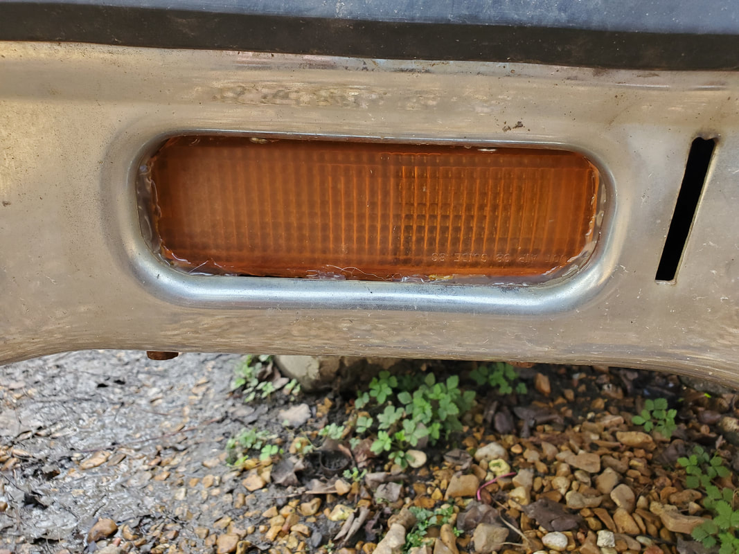
Right turn signal light mounted in place behind the bumper and wired up, ready to go.
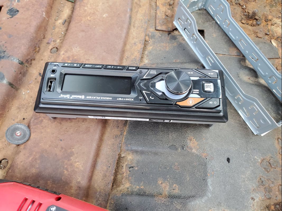
The media player car radio that will be mounted in place in the dash. Note how small the unit is.
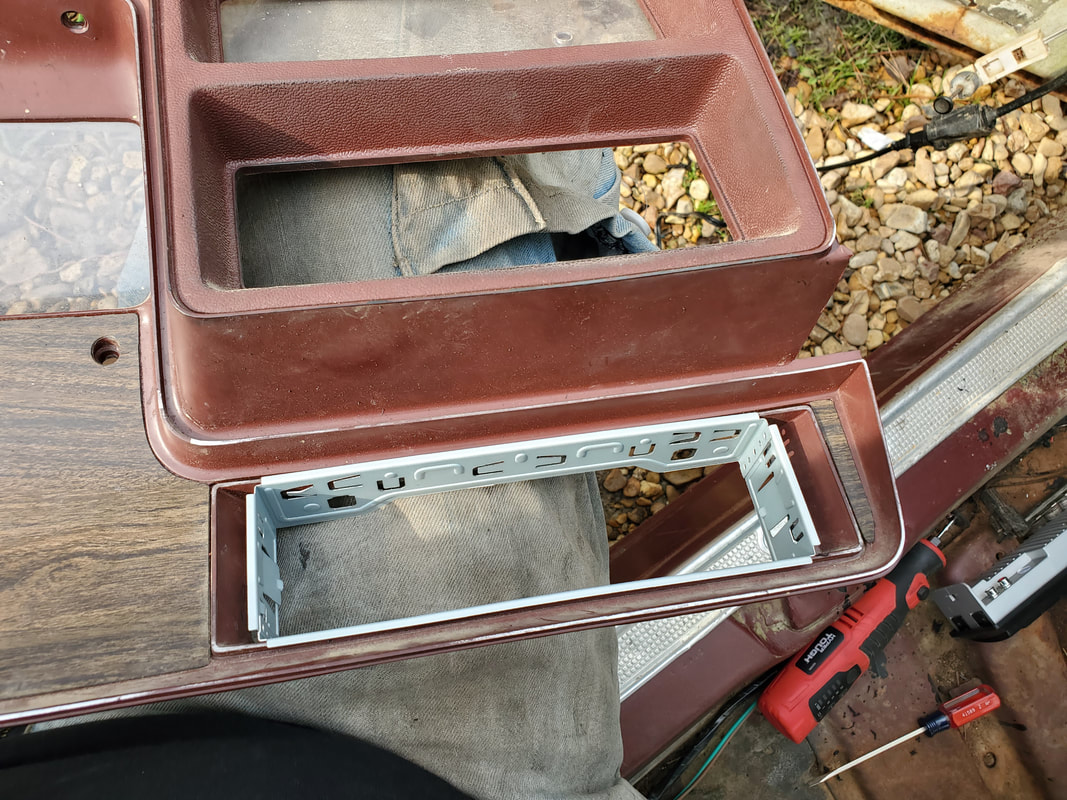
After trimming the opening in the dash trim panel, the mount shell is mounted, and the retaining tabs are set to hold the mount in place on the panel.
Back of dash panel showing the depth of the radio mount shell and the tabs used to lock the mount shell in place.
With the dash panel mounted back on the frame, the wire harness is brought out to plug up to the radio prior to sliding the radio into the shell.
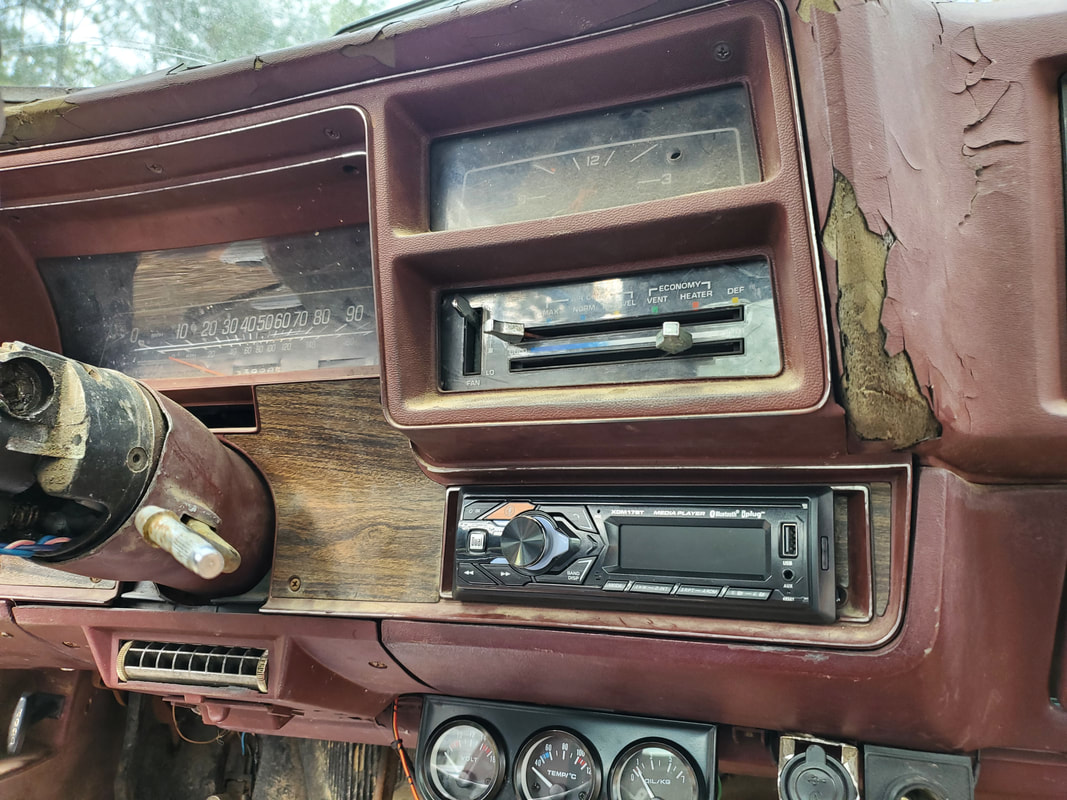
Radio mounted in shell in dash panel. Note the oversized lip of the radio face, covering up the edges of the mount that have gaps between the surface of the dash panel and the back of the radio face's lip.
Inline fuse wired in place to supply power to the constant 12v circuit that will feed the radio, interior lights and 12v receptacles.
To conclude the electrical job on the Elco, I had to address the problem of the bundles of wires passing through the holes in the firewall. There were two bundles to deal with. The first one was a small hole. To protect the wires I took a small square piece of rubberized PVC sheet and cut slits on one end of the square. I wrapped the PVC around the bundle of wires then slid the wrap into the hole while still wrapped around the wires. The tabs from the slits were opened up and tacked to the firewall with sheet metal screws through holes drilled around the hole. The other hole in the firewall was much larger and as a result called for the use of a piece of radiator hose. I did the same thing, cutting the hose piece lengthwise then wrapping the hose around the wire bundle. Slits cut on one end created the tabs that I would tack to the firewall with sheet metal screws through holes drilled in the firewall. With these wire bundles wrapped up we won't have to worry about any wires being damaged and causing a short.
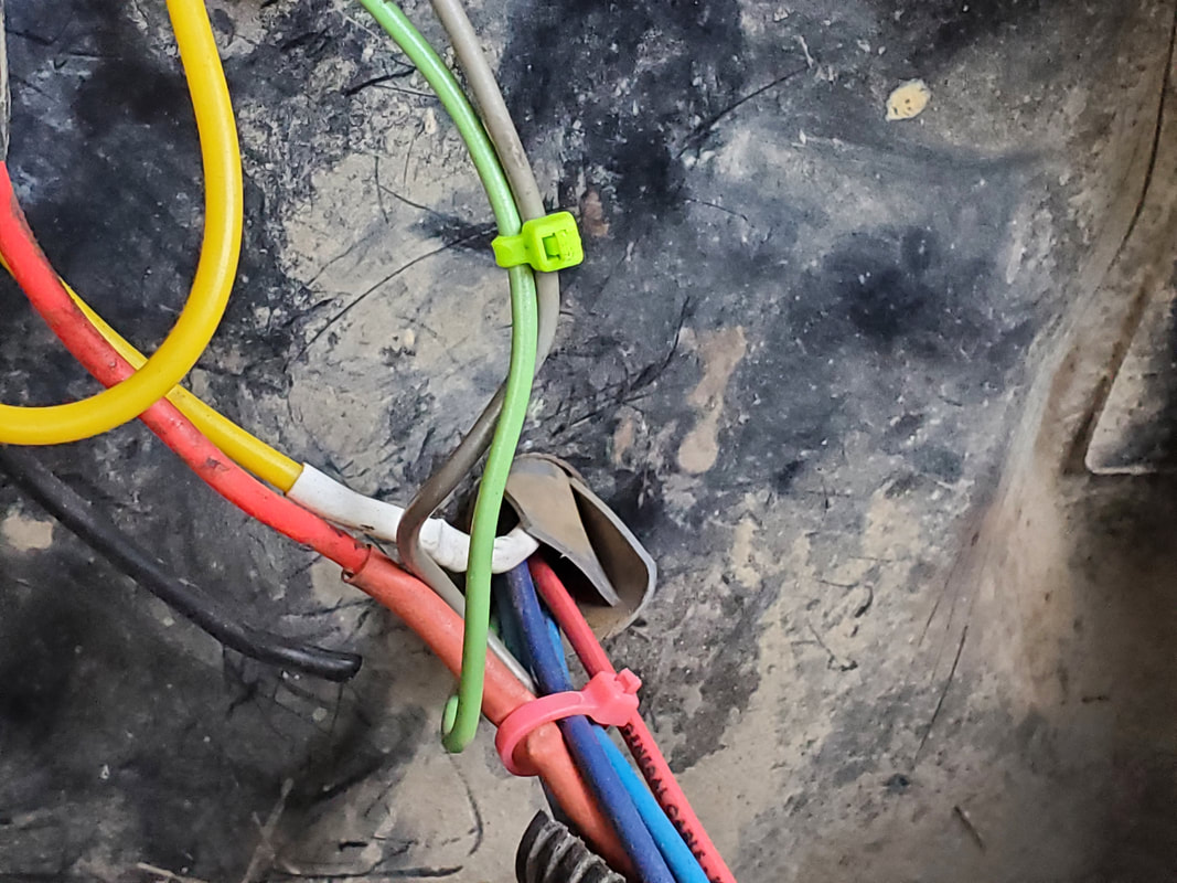
Sheet PVC wrapped around wire bundle and tucked into hole.
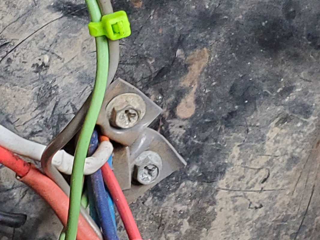
Tabs on PVC roll tacked to firewall with sheet metal screws.
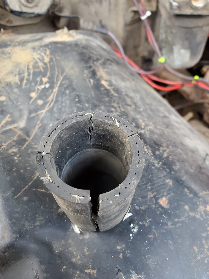
Piece of rad hose cut up in preparation for fitting in hole while wrapped around wire bundle.
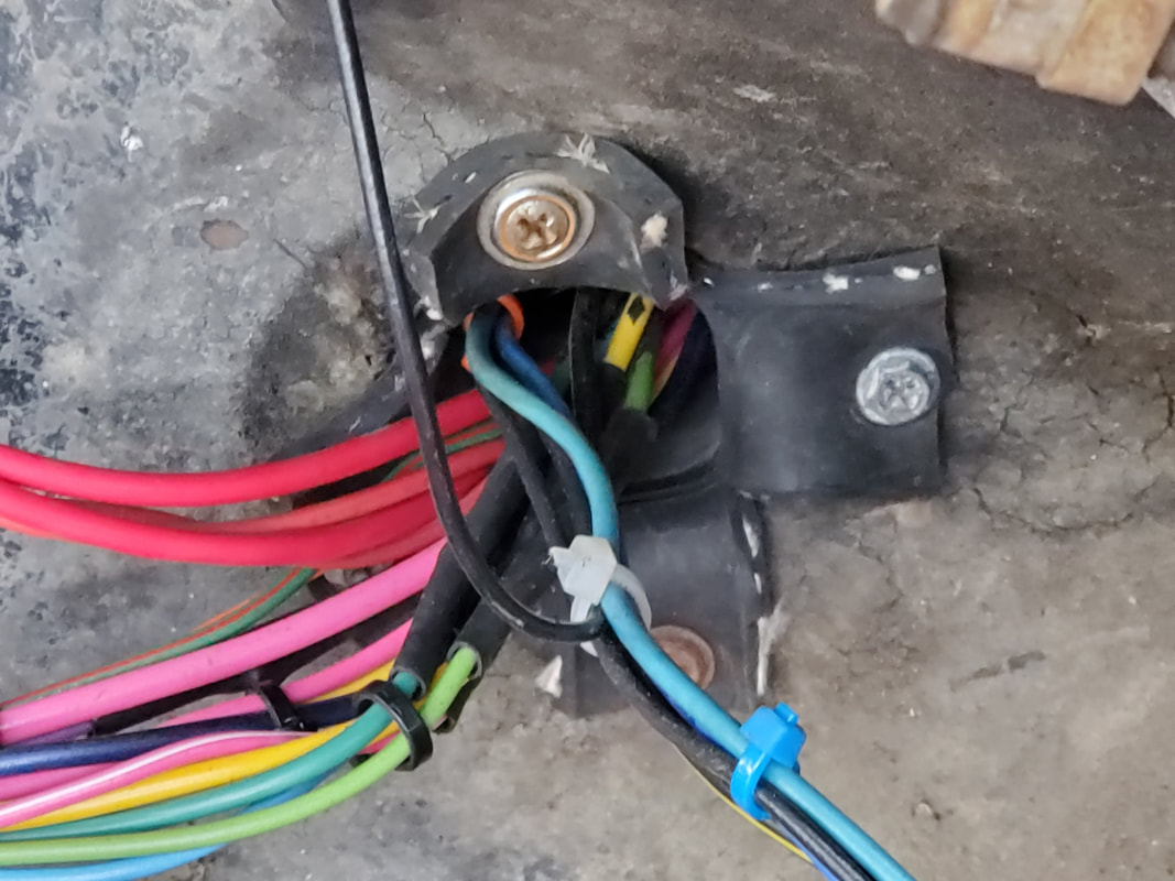
Tabs on hose tacked to firewall with sheet metal screws.
With the electrical system done the next area to work on is the interior of the car. I have most of the pieces that are important to restore the interior, including the door panels and trim pieces that go around the door/window openings. Starting off with the rear pillars where the trim pieces go up alongside the rear windows, I gathered the two pieces for each side. Since the old speakers that were mounted under these panels are dead and gone, there will be no worry about taking any speakers into account. After mounting the two sets of trim pieces around the rear pillars going around the top of the door opening, I moved on to the intermediate pieces that go between the A-pillar trim pieces and the ends of the rear pillar pieces, at the upper junction of the A-pillar and the roof. These pieces overlap to help cover the seams in the cab's sheet metal where the spot welds are. With those pieces installed I moved on to the door panels. Just like the rear pillars, the door panels come in sets of two. The upper half is padded with particle board underneath and the bottom half is just a plastic panel. Both panels use plastic pegs to snap the panels into the door shell, with the exception being the few screws that go along the top of the bottom panel to further secure it to the door.
Now even though I had all the pegs, some were dry rotted due to the age of these pieces and needed replacing. Also, since the particle board on the upper panels was degraded enough that they wouldn't ever hold any of the pegs, I had to resort to improvisation in order to secure them to the door. This involved drilling holes along the bottoms of both panels and using sheet metal screws with fender washers to hold the panels to the door. The tops of the panels hook onto the tops of the door so there was no worry there. At first, I put only three screws/washers on the passenger side since it was pretty solid. The driver's side was distorted enough that it needed five screws and washers. As a result, I added two more screws and washers to the passenger side to even things up. Last thing was the arm rests. Because the metal that makes up the body under the padding was rusted badly, I was unable to secure the armrests to the lower panel. I ended up drilling two holes through each armrest, down through where the screws would've been anchored to, then down through the metal brace on the door that helps support the arm rest. 3 1/2" deck screws with washers were used to pass through the arm rests and down into the holes drilled into the metal brace. I had to tighten both screws evenly to draw the arm rest down evenly onto the lower panel and have it down solidly on the brace. Even though I used a lot of screws and washers, I tried to keep everything even enough that it looks like it could've actually belonged. None of this stuff is installed in a haphazard way.
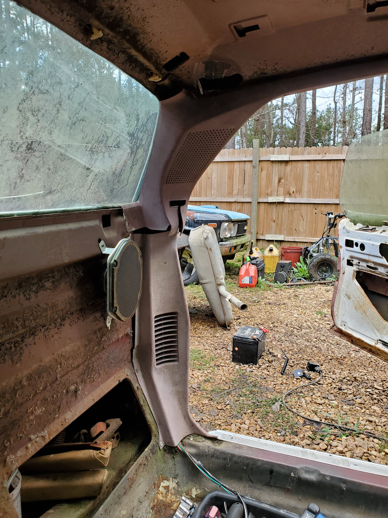
Trim pieces going up rear pillar. Top piece covers seat belt hardware and the speaker that used to set in this spot. As you can see, we mounted new speakers on the back panel of to the side instead.
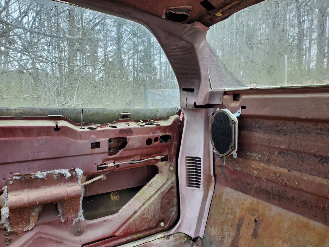
Same goes for passenger side here.
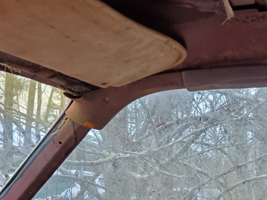
Intermediate trim piece going up over A-pillar and linking up with end of rear pillar trim piece.
Same goes for the driver's side where the A-pillar trim piece is in to better show how the pieces go together.
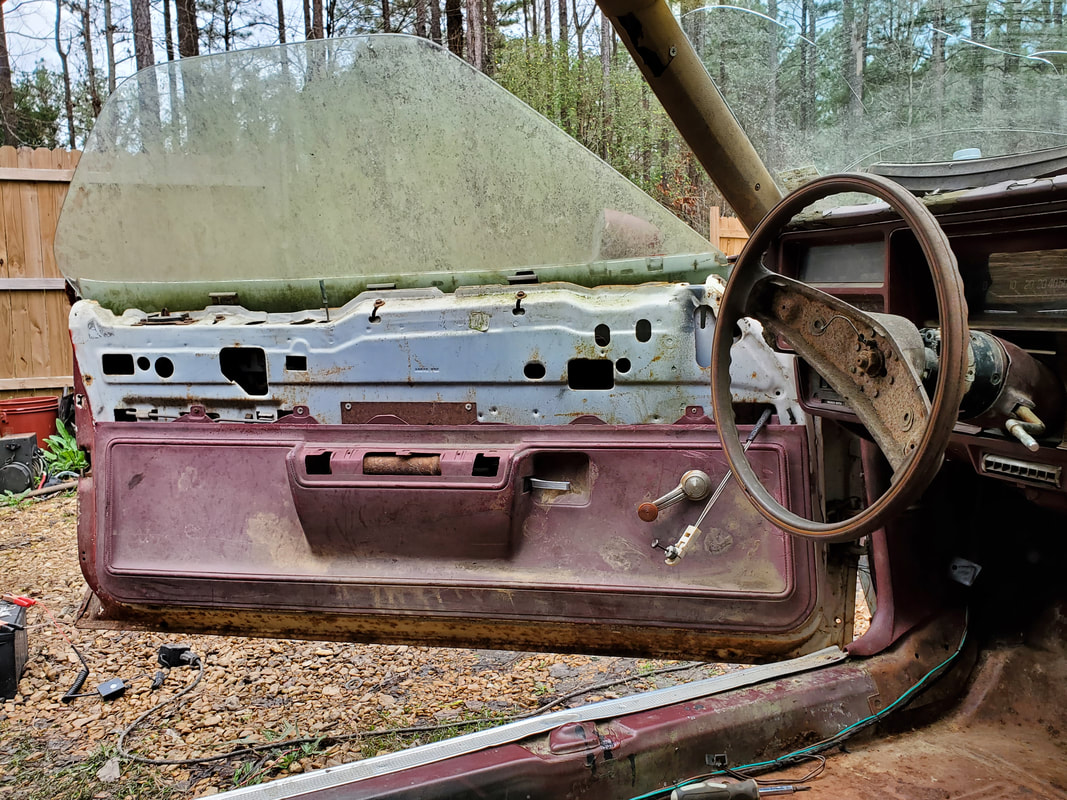
Driver's side lower door panel installed. note the screws along the top of the panel, and the window crank also installed.
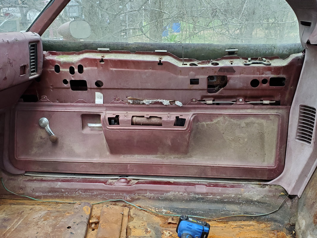
Same for the passenger side lower door panel.
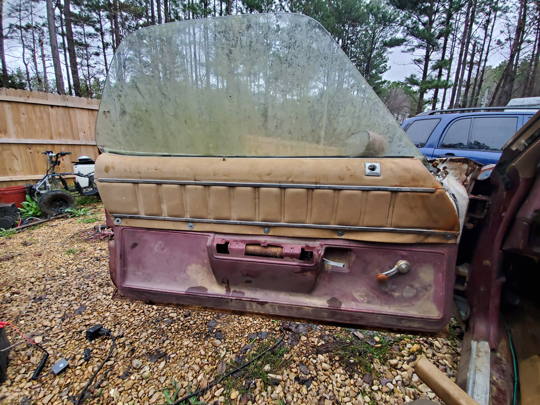
Upper door panel secured with five screws along the bottom. Top hooks onto door. Note the distortion of the panel along the front bottom corner of the panel.
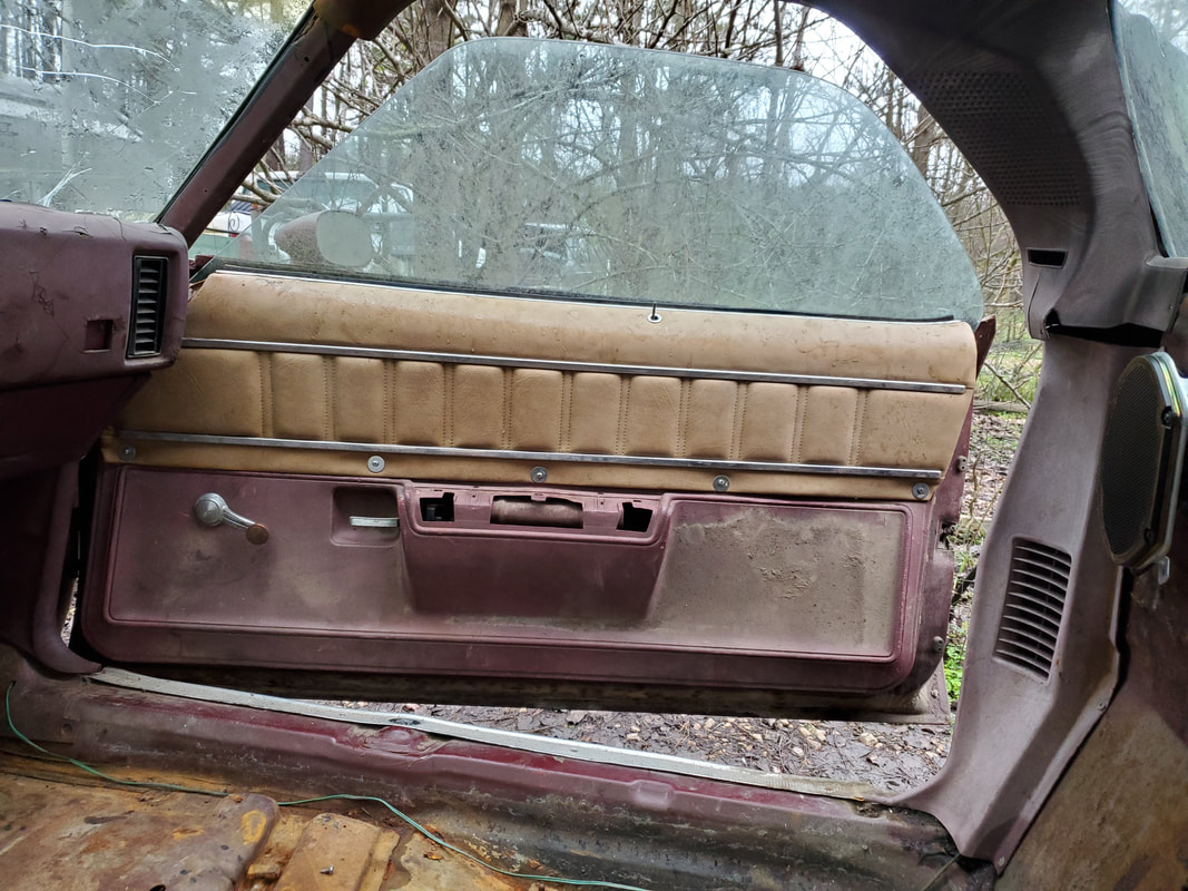
Passenger side panel in place as well. Two more screws were added along the bottom to make things even with the driver's side panel.
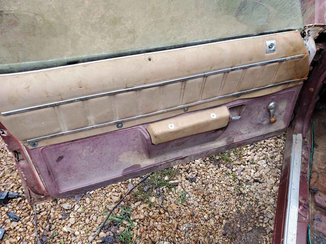
Armrest installed on lower door panel with deck screws through armrest and into brace underneath panel.
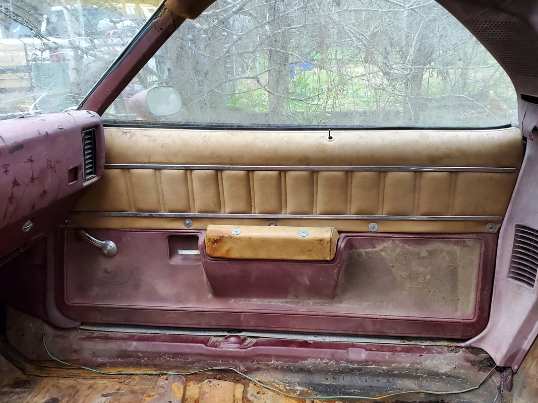
Passenger side armrest installed same as the driver's side. To the untrained eye this could almost look like its a factory install.
After thinking about it, i decided on a plan for the Elco's fuel system. Rather than spend a large amount for a stock sending unit for the fuel tank, I found an aftermarket universal sending unit that comes with a fuel gauge. Since the Elco's old fuel gauge is dead, replacing the stock sending unit would be pointless, I would've had to replace the stock fuel gauge too. At least with the aftermarket kit, I have a fresh gauge and sending unit. Only thing is I would have to cut a hole in the top of the fuel tank for the new sending unit. After installing the sending unit, I will have to hook up a single wire to the device and route the wire along the same route as the fuel pump power wire, placing it through the firewall where it will hook up to the gauge. The gauge will also have to be placed somewhere and hooked up with power for the gauge as well as power for the light, which would be hooked to the same circuit as the rest of the gauges, to the headlight circuit.
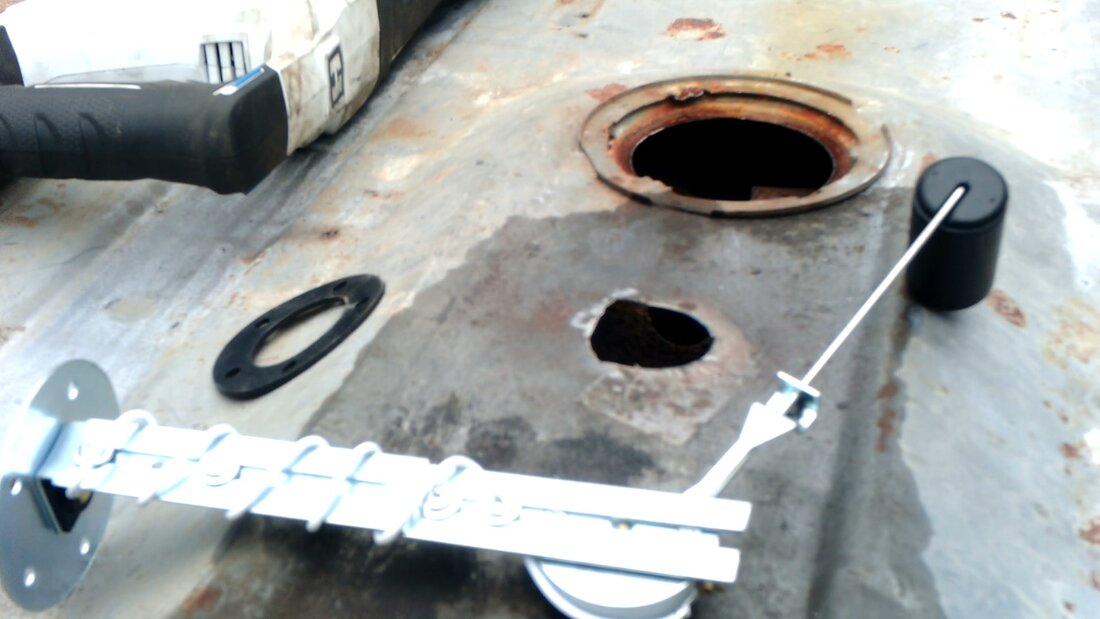
After a failed attempt to use a cheap hole saw, I had to drill a large hole with a step bit and then use a reciprocating saw to cut this jagged hole. Afterward a sanding wheel smoothed the sharp edges. I was able to use self tapping screws to secure the sending unit to the fuel tank.
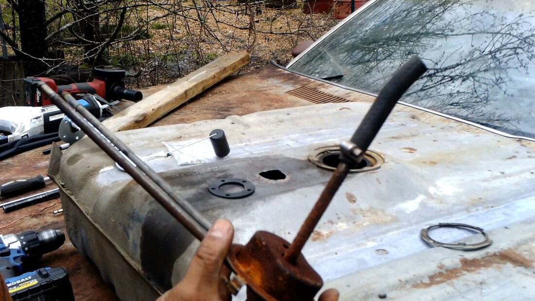
The old sending unit was reused as a fuel pickup. By removing the sending unit head and adding a piece of rubber hose to cover a small hole in the tube and to put the point of pickup closer to the bottom of the fuel tank. Once installed, the old fuel sending unit will serve only as a fuel pickup connected to the fuel pump via a piece of rubber hose.
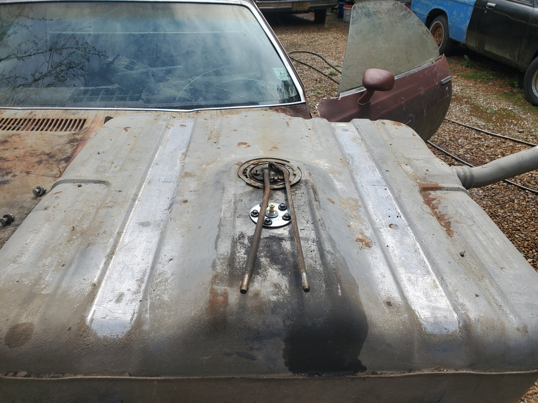
Fuel tank with both sending units secured in place. The tank is ready to reinstall.
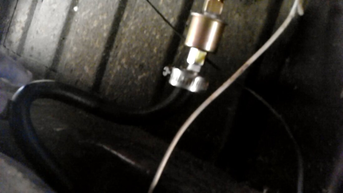
Rubber hose that connects the output tube from the old sending unit to the input nipple on the fuel pump assembly. The white wire is the wire connected to the new sending unit and is routed along the same path as the fuel pump power wire.
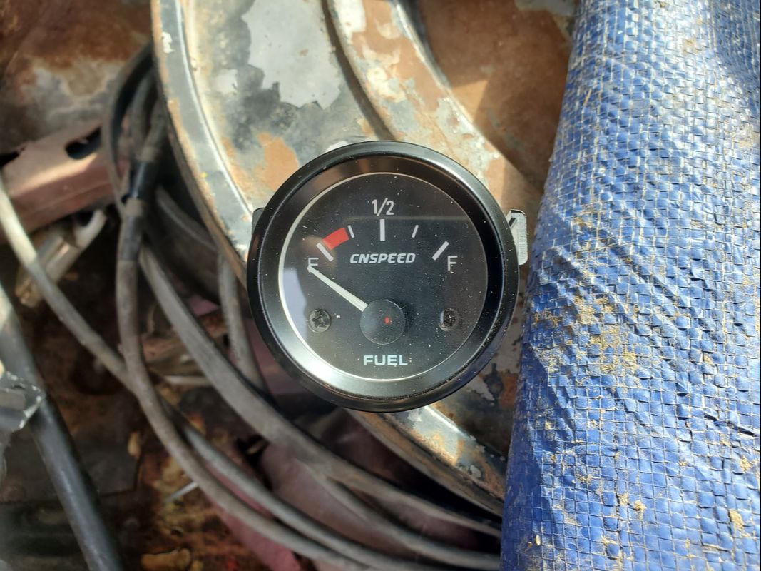
The fuel gauge that came with the sending unit in the kit.
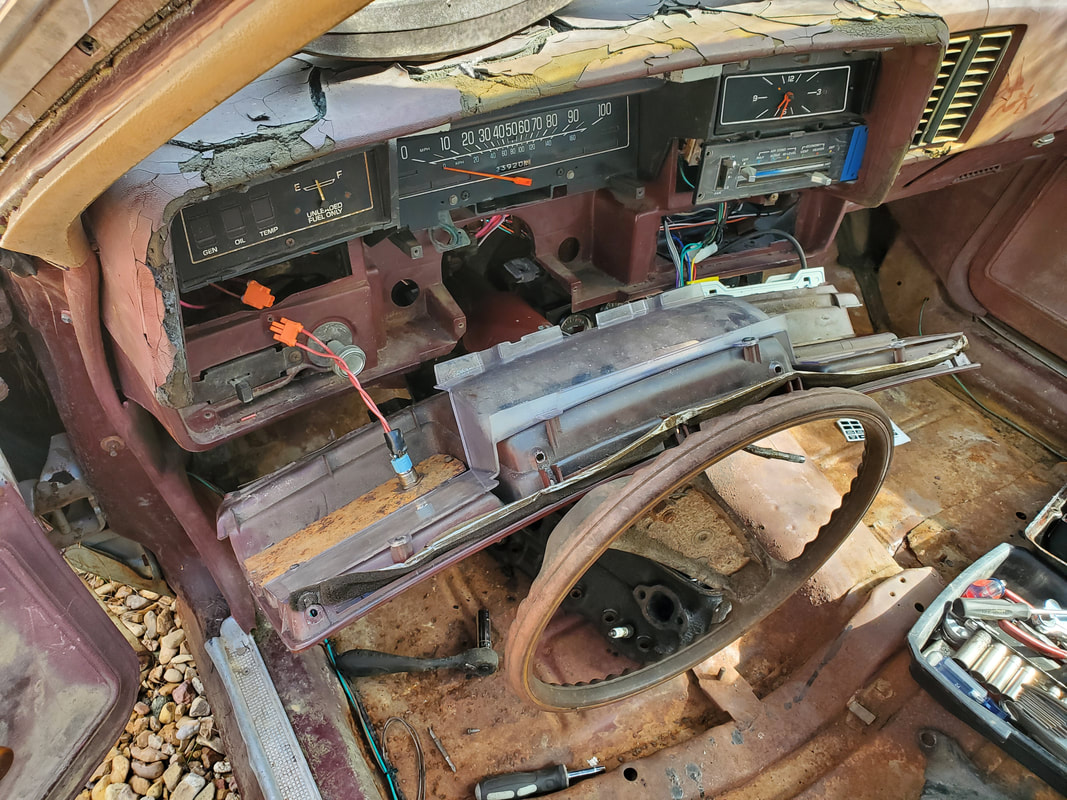
After finding that the sheet metal panel I installed earlier for the horn button has enough room, I pulled the dash panel off to remove said sheet metal panel. The steering column had to come down to remove the dash panel. I'll cut a hole in this panel for the fuel gauge.
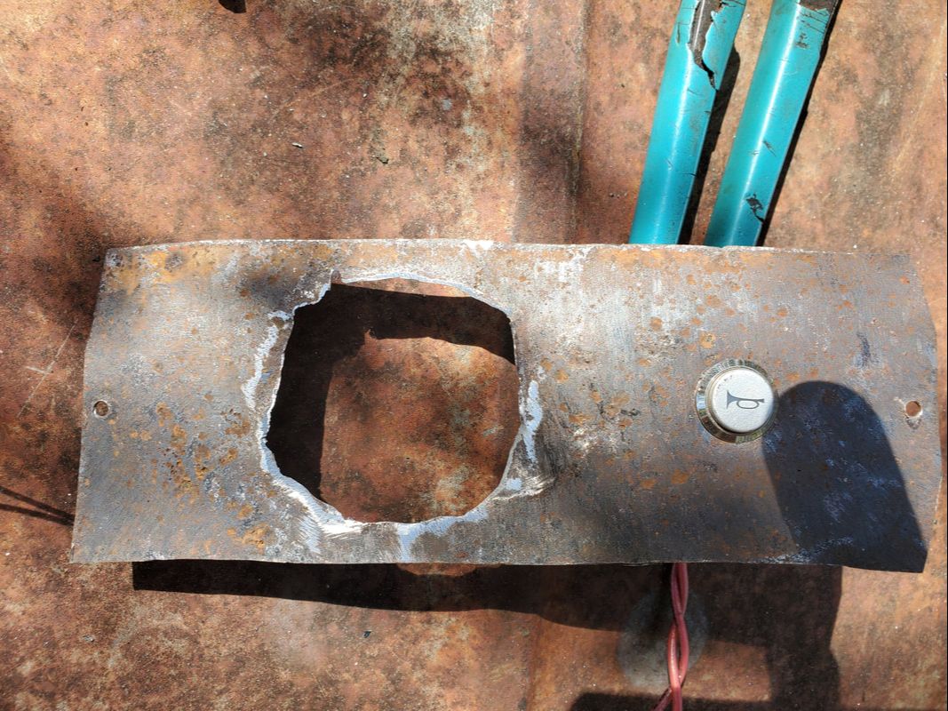
Like with the fuel tank, the hole saw failed to cut the hole. I had to drill a large hole then gradually cut away material until the hole was big enough for the gauge. Of course the hole looks bad.
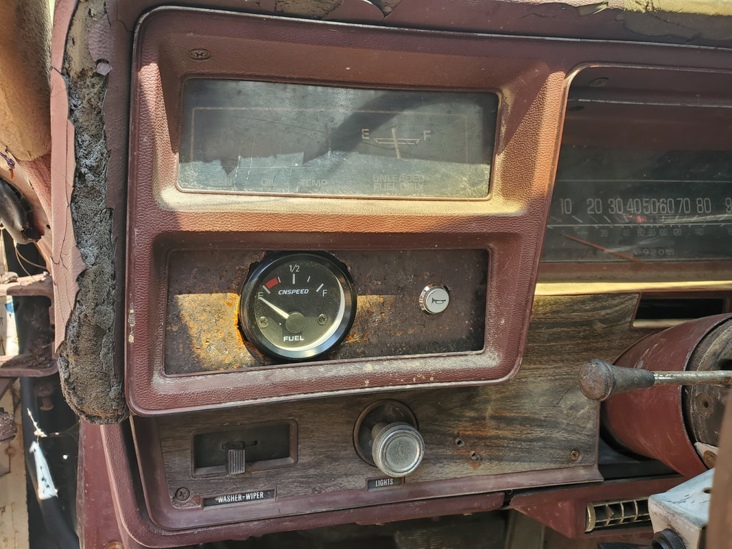
After splicing the wires for power and lights and sending unit, the gauge was installed in the sheet metal panel and the dash panel reassembled, completing the job. The gauge looks like it fits in this spot.
At this point we now take our business into the engine bay. The engine is a newer generation SBC with the center bolt valve covers. The intake I have is actually for the older generation version SBC with outer bolt valve covers. What this meant is I either had to spend a couple hundred bucks for the right intake to fit this configuration OR remove the heads from an older gen SBC. Luckily, I have two older gen SBC engines, one of which has all the accessories. I decided to hit that one and rob it of the heads and the accessories. What this also meant was I had to get a set of head gaskets, which was a lot cheaper than another intake. With that, I went ahead and removed the old newer gen heads, along with the push rods and exhaust manifolds. After cleaning the surfaces of the block and the heads, I applied the gaskets, then mounted the heads. I added the 17 bolts to each head then went through the torque sequence, of three settings, 25 ft/lbs, 45 and 65. With the heads torqued down, I cleaned the surfaces of the head where the intake is mounted then applied gasket maker to glue the gaskets down. With the gaskets down I bolted the intake down and made sure to go over the bolts a couple times to ensure all bolts were tight, since intake bolts have a habit of getting loose as the intake shifts during the tightening of some bolts. With the intake down, the next move will be bolting on accessories, starting with the water pump. The water pump, as it was removed from the engine, has the fan/clutch and pulley attached to it. I chose to remove these items before applying gaskets and bolting the pump on, to make things easier.
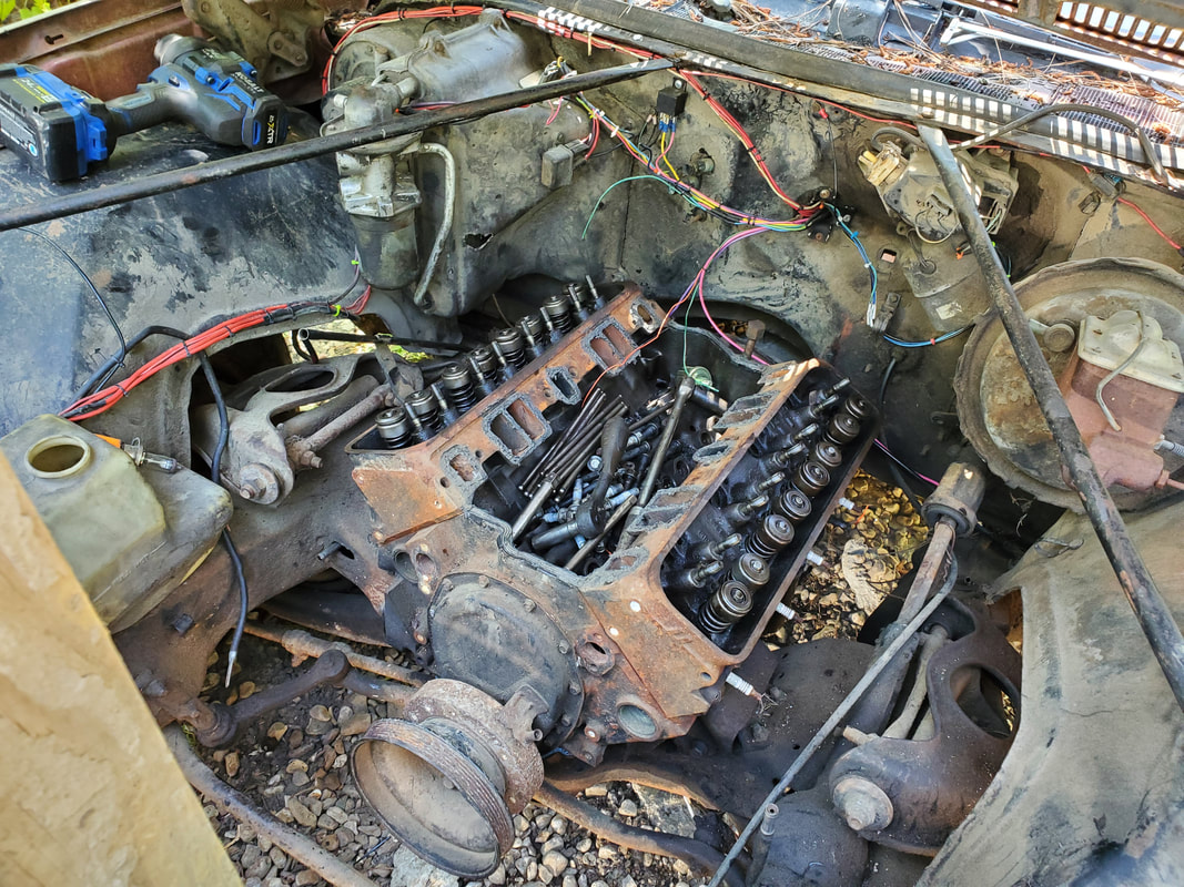
Engine with newer generation cylinder heads. Rocker arms were removed along with push rods.
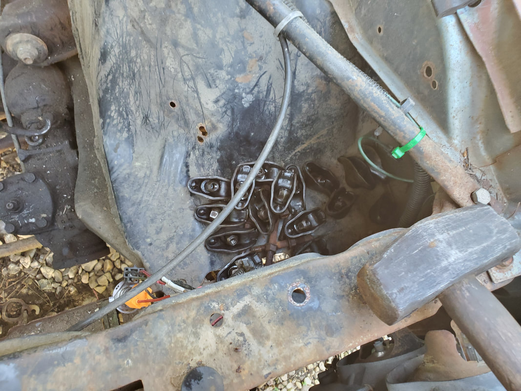
Rocker arms pulled from top of cylinder heads prior to removing of heads.
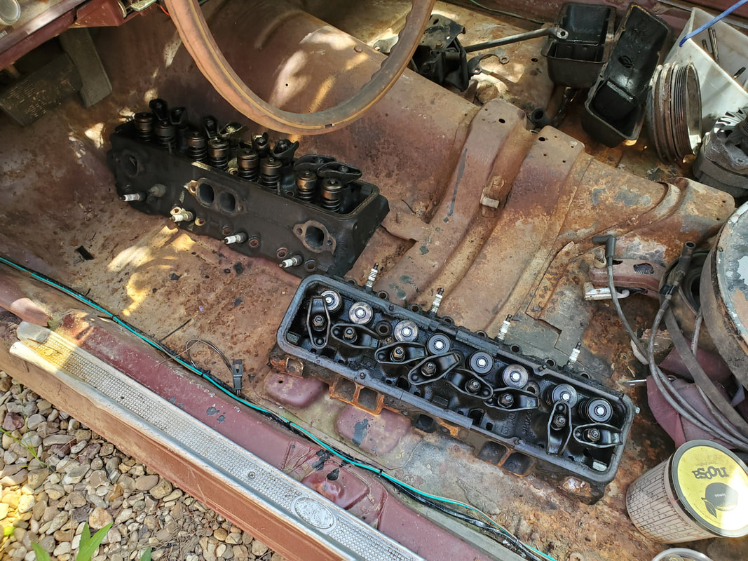
Set of older generation heads removed from other 305 in garage, along with accessories and brackets.
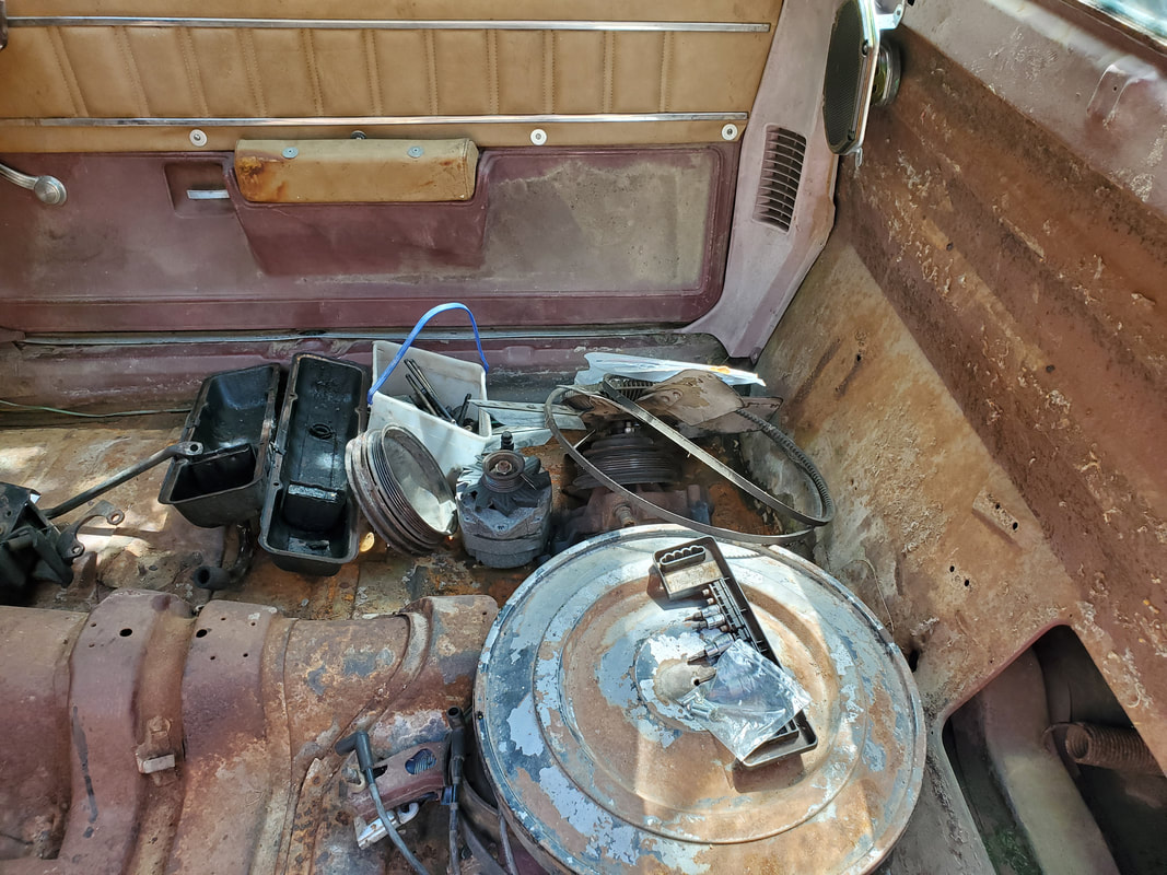
Other accessories and brackets removed from older 305, to be installed on Elco.
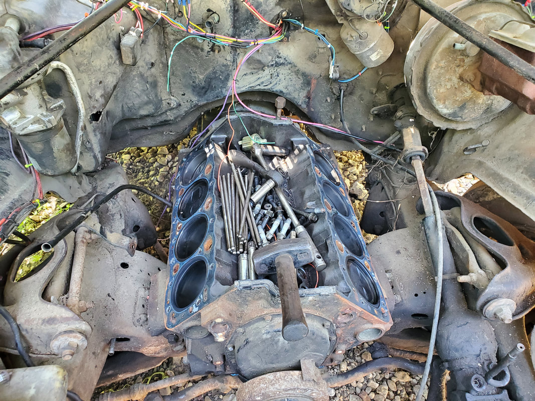
Engine with cylinder heads removed, push rods are still in lifter valley.
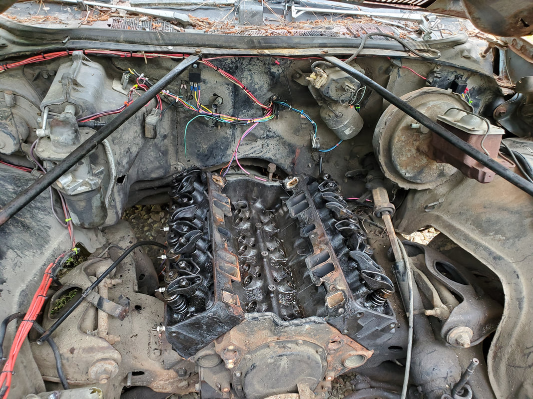
New old cylinder heads secured and bolted down to top of engine.
Intake manifold bolted down on top of engine. Also note the push rods secured in place under rocker arms on heads.
Fan/clutch, pulley and water pump assembly, prior to disassembly and mounting.
Water pump after removing other components. Now I can glue the gaskets in place for this part of the job.
Exhaust manifolds that will be used on this car. Unlike the exhasut that was on this engine, these pieces have short pieces of flange pipe attached, which will make it easier to fabricate an exhaust since I won't have to get the entire length of flange pipe with flange. f
Moving along to the water pump, I glued on the gaskets then bolted the water pump in place. One of the bolts had to be further sealed with gasket maker since the bolt hole passed through to the water jacket. With the water pump on, I moved on to the accessory brackets. The power steering pump already has a bracket bolted on to it. An intermediate bracket gets bolted onto the driver's side cylinder head. The PS pump's bracket is bolted to two points around the water pump, hanging on a stud on the top most point and a bolt on the lowest point. I tried to bolt the AC compressor bracket in place but because this bracket is made for use on the stock intake manifold I was unable to place it down where the holes lined up with the aftermarket manifold. I ended up having to grind away some material from the AC compressor bracket to allow the piece to fit around part of the body on the intake that kept the bracket from fitting. After bolting the bracket down, I was still left with a bar that extended backwards to the middle of the intake. Unfortunately, this piece didn't line up either, so I'll have to do some type of reconstructive surgery to make that piece fit as well. I won't bother with this until I do manage to restore the AC system since this bracket is only critical for holding the AC compressor.
With the AC compressor bracket down, I tried to use the last bracket I thought was for the PS pump. While I tried to figure that out I took a moment to bolt up the alternator bracket and secure the alternator so I can get that out of the way. Once that was done, I went back to the PS pump. The last bracket I had turned out to be another PS pump bracket that was actually used on the Monte when it had a V belt configuration. The bracket was like the outer half of the current PS pump bracket. What this meant was I had no bracket to secure the rest of the PS pump. I ended up deciding to fabricate a bracket from an old Ford 302 accessory bracket. I trimmed it down and drilled a couple holes to line up with the bolts holding the bracket to the driver's side head. The bracket piece has a curved slotted hole that will bolt up to the outer end of the PS pump bracket and allow for belt tension adjustment on the piece. I ended up having to use washers and a nut for spacers between the bracket pieces. With the bracket fabricated, I bolted the piece in place and secured the PS pump to the bracket as intended, tensioning the belt in the process. I tried to move the PS pump around and found that the piece was secured nicely enough that my fabricated bracket was successful.
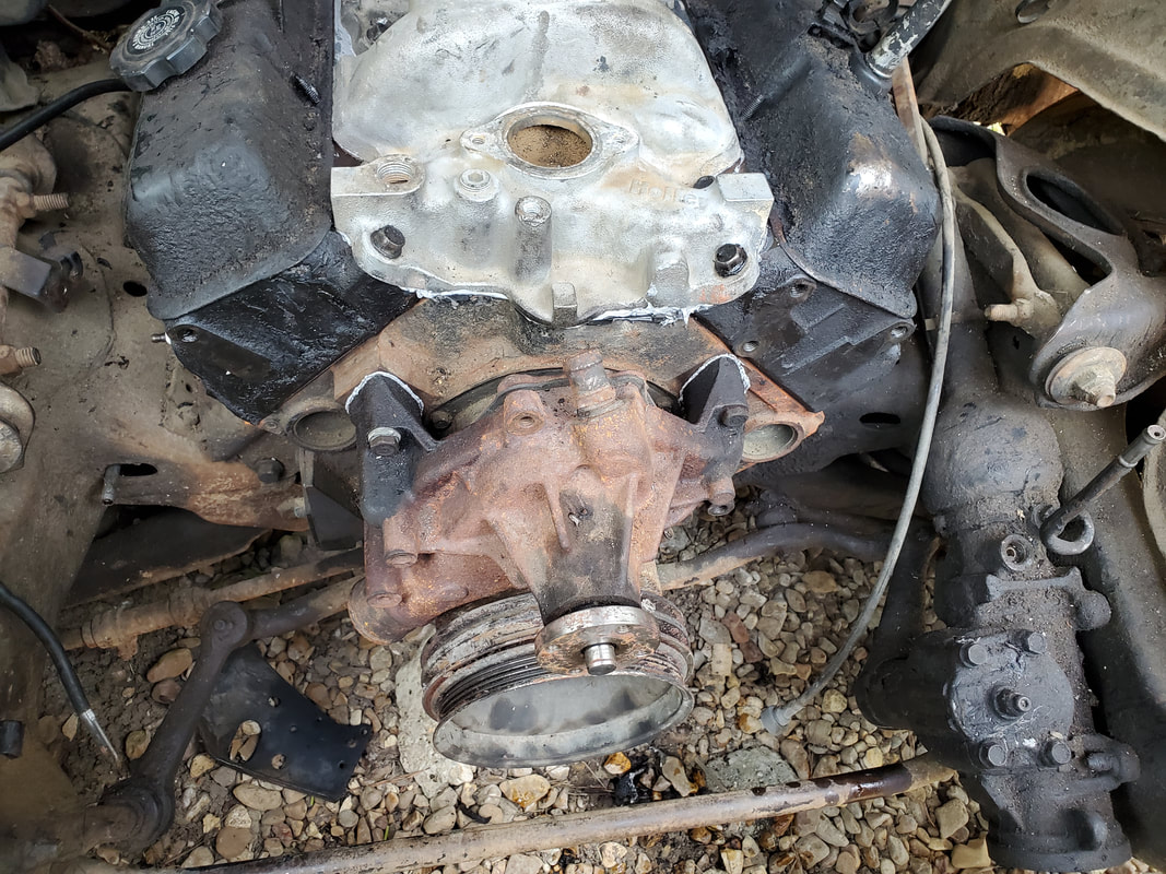
Water pump bolted in place against the block. One of the bolts has gasket maker sealing it due to the bolt hole passing through the water jacket.
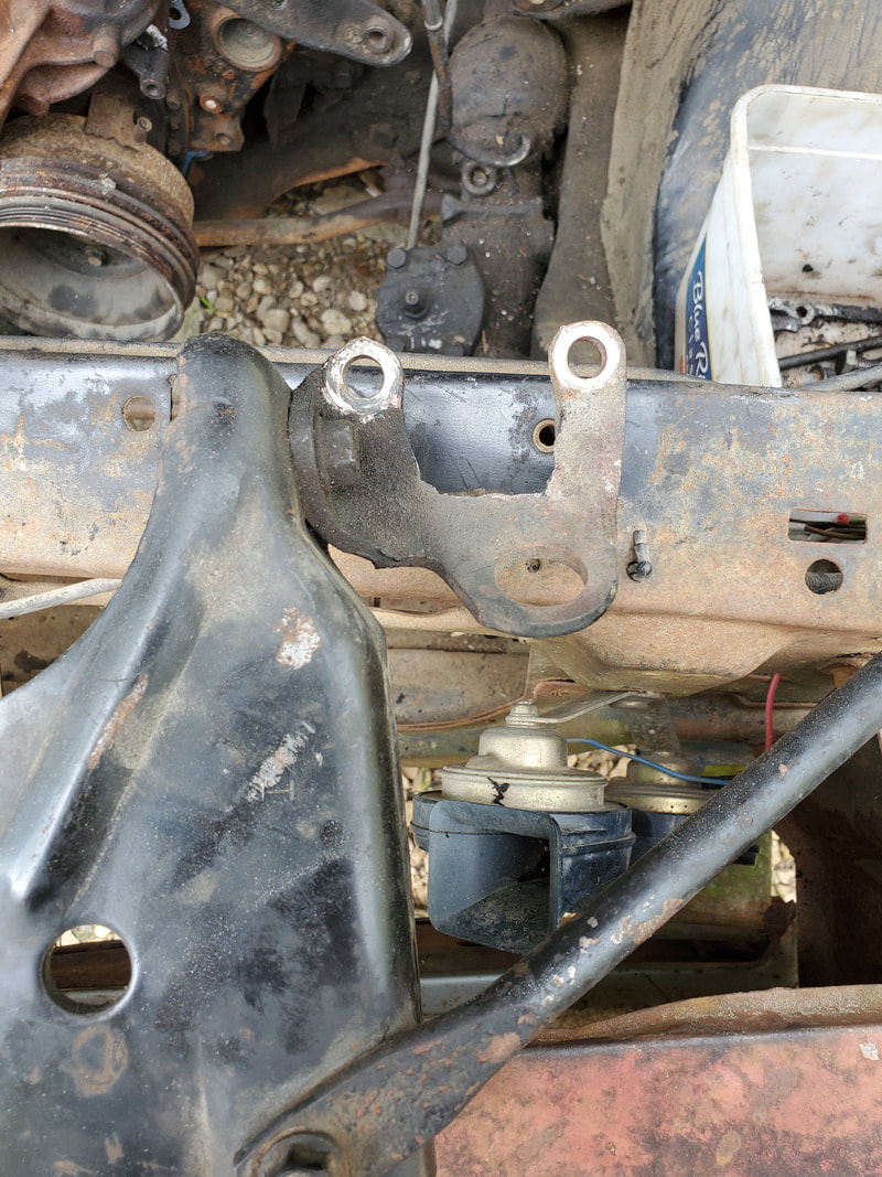
AC compressor bracket after grinding out metal to allow the piece to fit around body of intake manifold and be bolted in place. The bar in the lower right of the pic still didn't line up and will need to be tweaked to make it fit later.
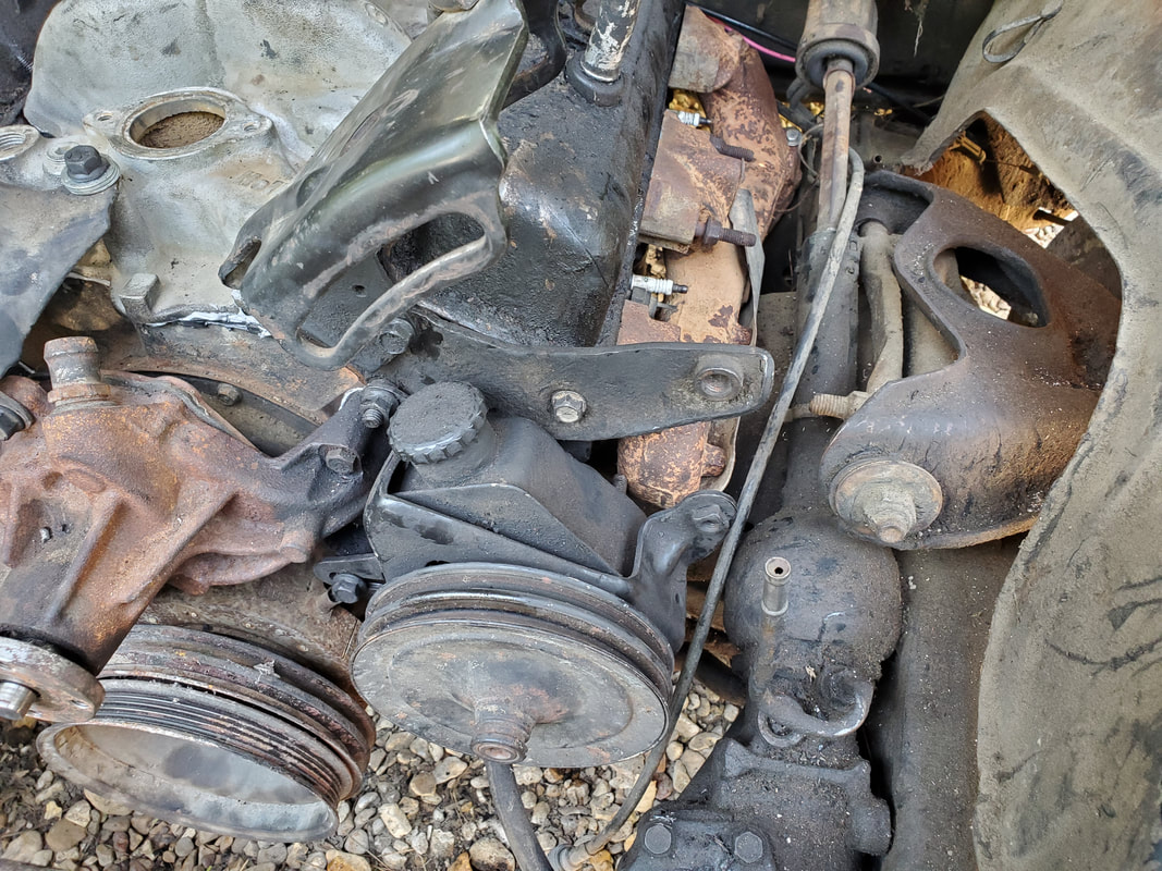
Power steering pump bolted up on water pump side, note the gap between the PS pump bracket and the intermediate bracket bolted to the head.
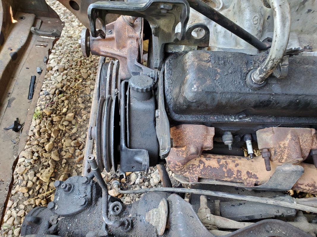
Side view of the PS pump and intermediate bracket showing the gaps to be covered between the two.
Alternator and associated bracket bolted in place.
Ford accessory bracket in the first stages of its reconstructive surgery for use as a SBC PS pump bracket. The tab cut off the corner is to allow the bracket piece to fit alongside the PS pump to line things up for fitting.
Bracket after carving out the unneeded metal and drilling the necessary holes to line up with the bracket bolted to the head. Some part of a ridge on the bracket was ground to allow the piece to fit flusher against the intermediate bracket as well.
Power steering pump bolted in place with the new fabricated bracket showing the nuts and bolts and spacers used to hold everything together. Pump is tensioned against belt as well.
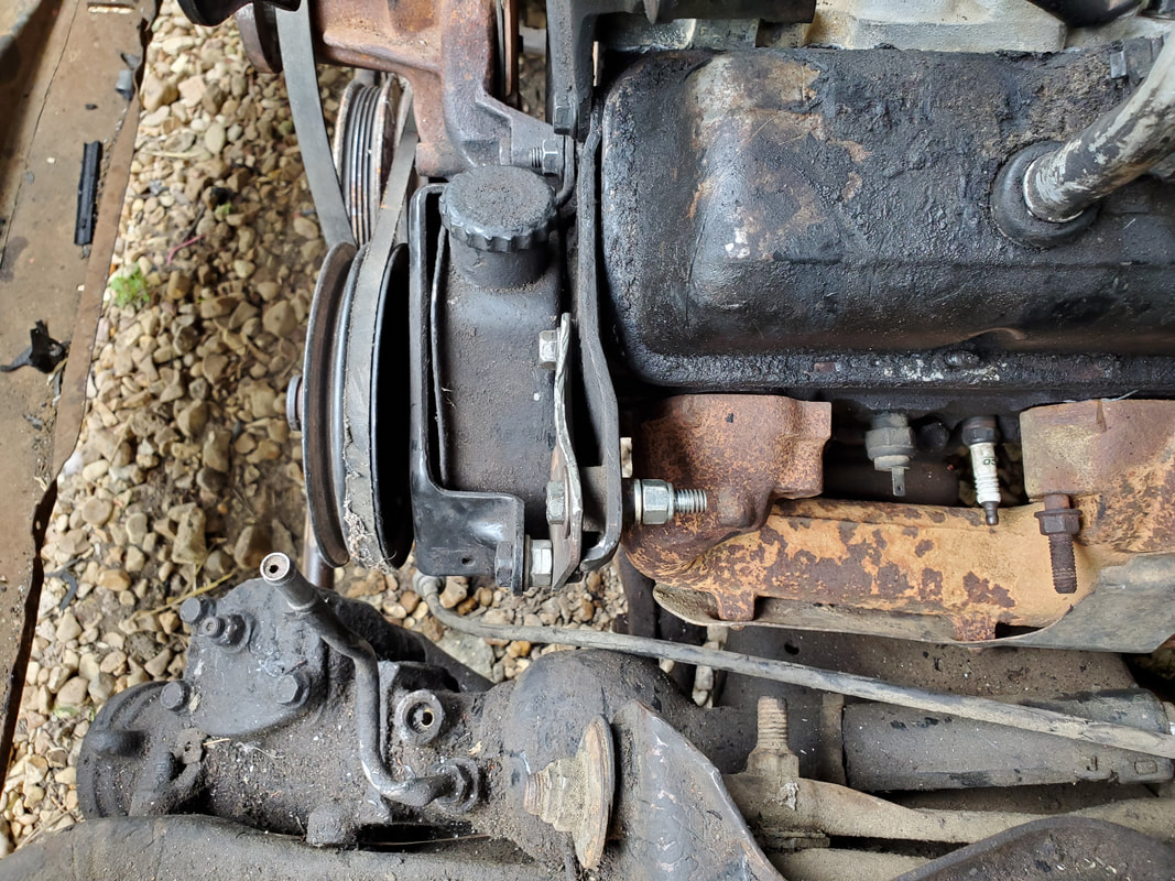
Side view showing how the bolts and spacers are applied to hold everything together.
Moving to the water pump and the pulley and fan/clutch, I needed replacement bolts for the shaft mount. After getting these bolts, I was able to mount everything to the water pump. I added the belt as well, tensioning the belt with the alternator. The bolts did need some spacer washers since they were a little long and the threads in the water pump shaft mount were a little boogered up. I didn't want to try and force the bolts all the way through for fear of breaking the bolts, despite them being grade 8's. Also trying to hold the shaft stationary in order to deliver the torque necessary to tighten the bolts would've been just as immense. Moving along, I went to mount the exhaust manifolds. We ran into a problem here though. Because these heads are apparently an older pair, the bolt spacing for the rear exhaust port are off by a quarter to a third an inch. I can get the middle and front bolts secured but the last port's bolts are off a bit. On the passenger exhaust manifold its the front port that's off a bit. Since I didn't want to spend money replacing these exhaust manifolds as that would be the same as getting a replacement intake which would've negated the whole purpose of this engine retrofit, I decided to modify the current exhaust manifolds. To do this I cut the bolt mounting points into slots by cutting out metal. Since one of the bolts would be off center towards the port wall, I had to grind metal away from that section of metal, which will compromise the integrity of the port wall. I left enough metal to not fully break through the port wall on both manifolds. From there I applied the bolts and hooked the gasket pieces in place over the bolts, then carefully tightened the bolts so as to not strip, cross thread or fully break the bolts, since the bolts were snug against the metal of the manifolds. After enough careful tightening, I did get both manifolds snug against the heads. More than likely this shit is going to have exhaust leaks, hopefully not so much that it'll burn spark plug wires or anything else. With the exhaust manifolds down, I installed the distributor. Even though I didn't find TDC by cranking the engine, it really doesn't matter. When I do crank the engine for TDC, wherever the rotor points is where #1 plug wire goes. With the distributor down, I'm pretty much done with the engine bay for a spell. I will need to get some more stuff before I can finish up fully in the engine bay. In the meantime I turned my attention to the interior.
I started off with the seatbelt reel assemblies. I had to remove a couple interior trim panels to better access the bolts to hold the upper reels in place. With the upper reels bolted down, I tried to remove the bolts from the floor for the bottom reel pieces but they were frozen in place. Since I'm not going to be able to remove these bolts without breaking them or my tool, I'll just weld in some kind of plate to serve as an anchor point then drill a hole through the floor for a 1/2" bolt to hold the bottom reels in place. In the meantime I did go ahead and bolt down the female buckle assemblies. Even though the holes were ugly, I cleaned them up and wet them up with WD40 and slowly worked the bolts in, managing to get them all the way through safely, securing the female buckle assemblies in place. I did have to use WD40 on one of the female buckles as its button was rusted up. Once I freed the button up, I could write that off as good. With the seatbelts 2/3 installed, I will figure out what I want to use for the full install o the bottom reels, as well as the seats.
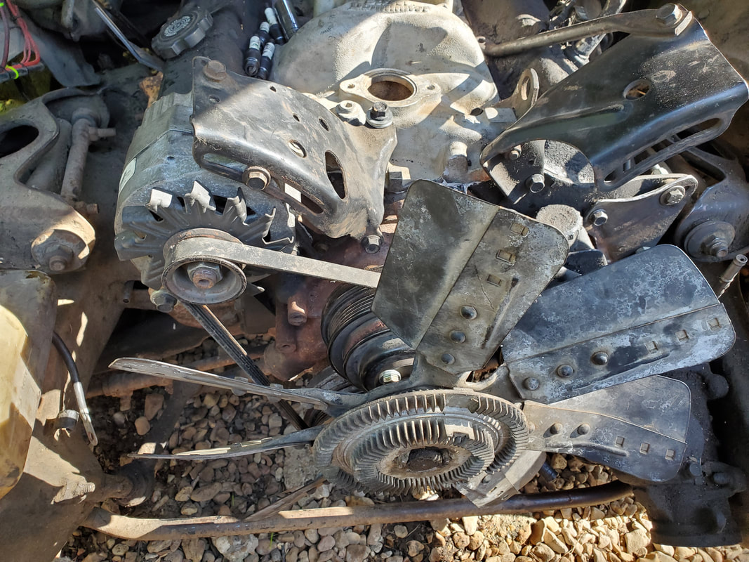
Water pump with pulley and fan/clutch installed using new bolts with washers for spacers. Belt is also installed for alternator and crank.
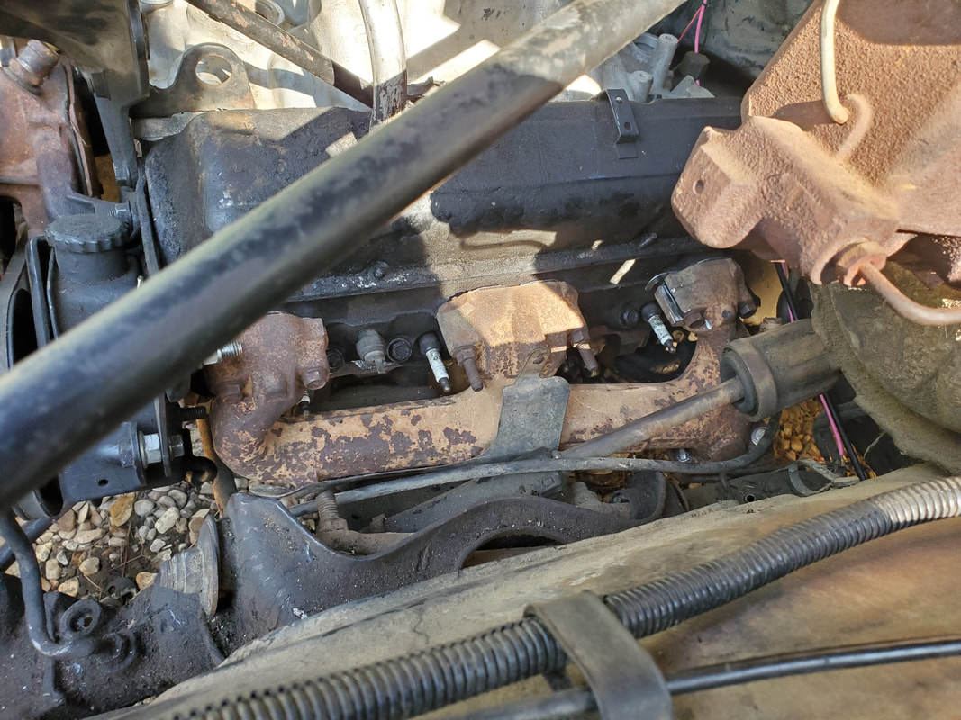
Driver's side exhaust manifold installed after modifying rear port al allow for fitting on the oddball cylinder heads.
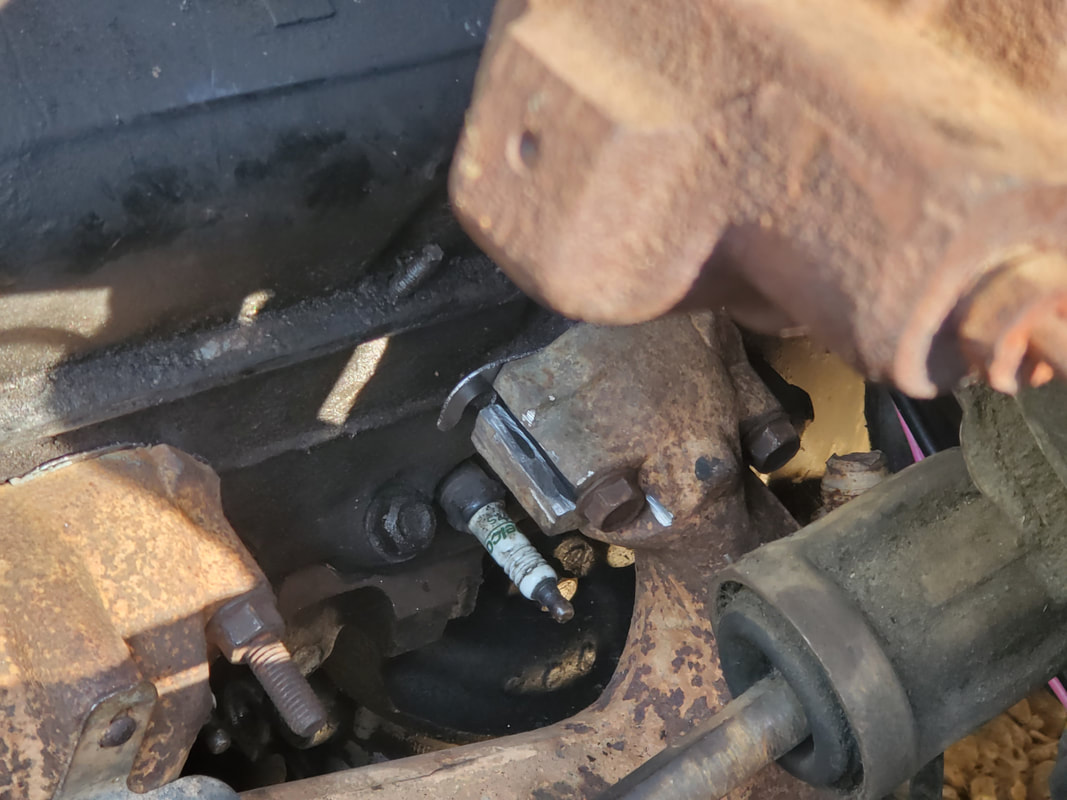
Closeup of the slotted mounts of the rear port showing how the inner slot bolt is in closer to the port while the other is out from the port more.
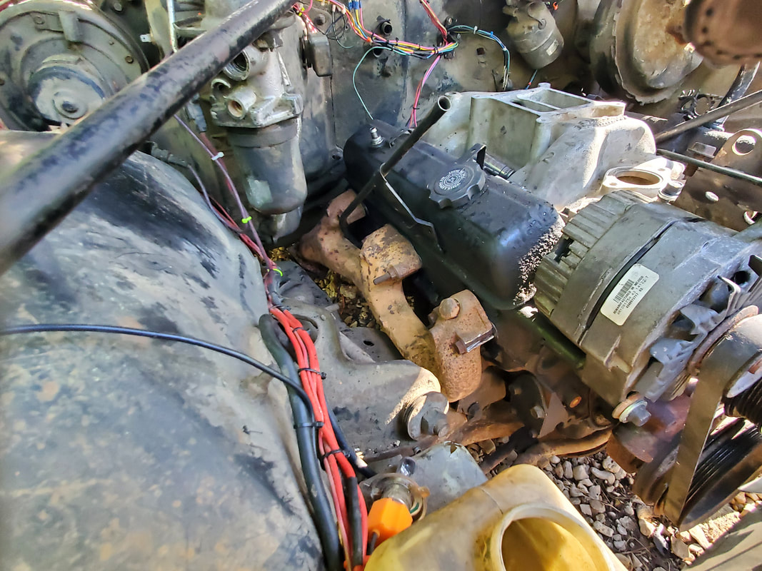
Passenger side exhaust manifold bolted in place. This head is opposite of the driver's side with the front port being off a little bit. The same rules applied to these bolts and the idea of adding slots for the off-center placement of the bolts.
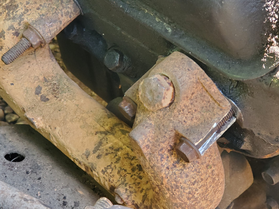
Closeup of the slotted mounts and the bolts showing how the outer bolt is out from the port a bit.
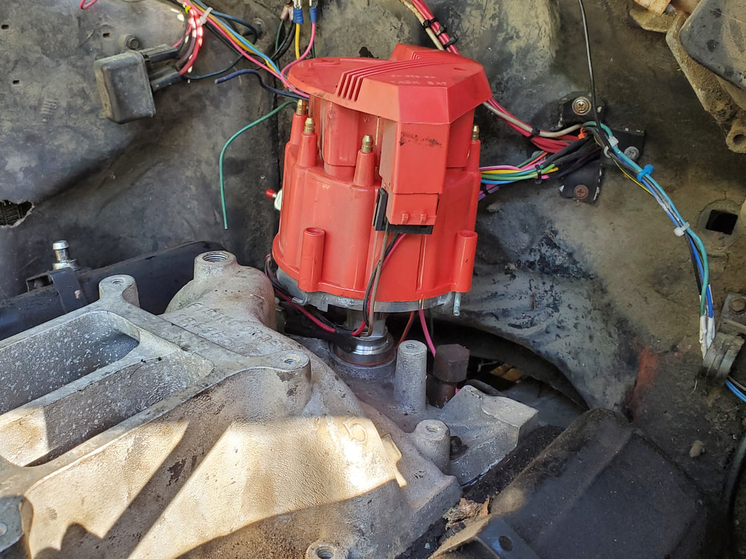
New HEI distributor installed in place.
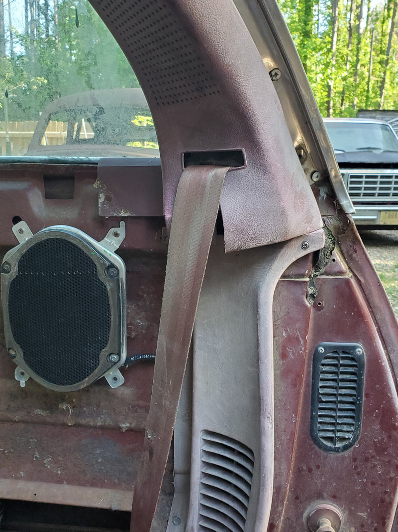
Driver's side upper seatbelt reel installed to mount under panel, with lower panel reinstalled afterward.
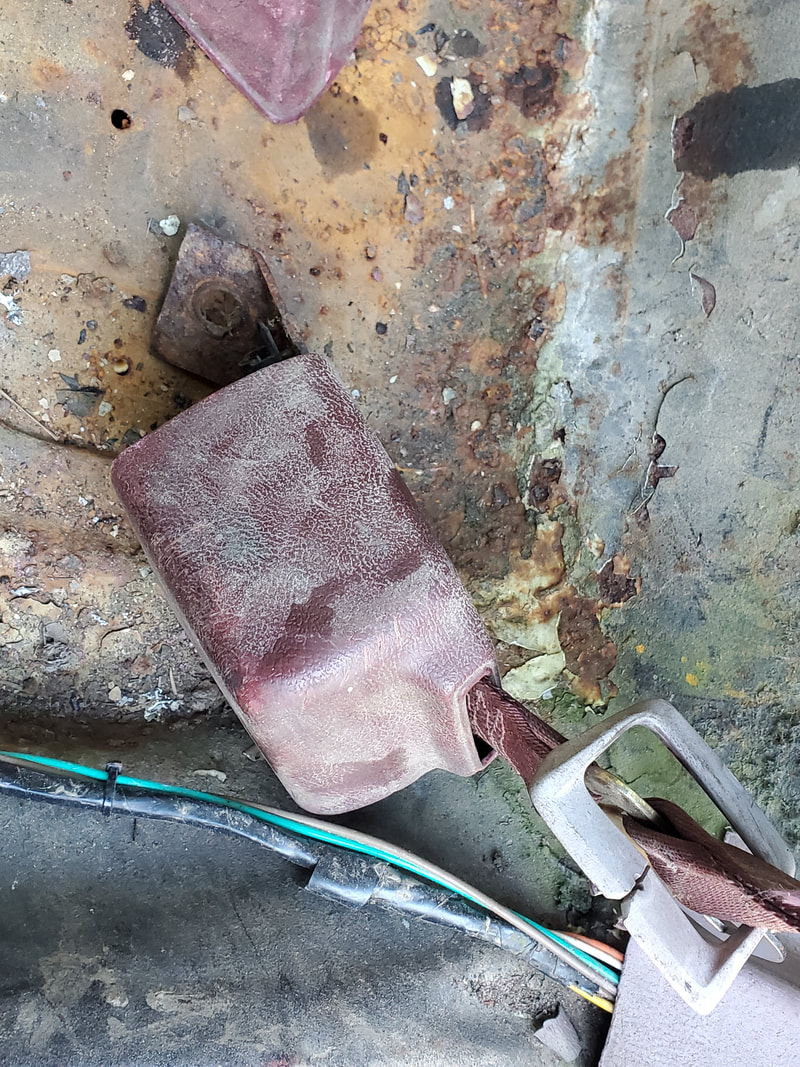
Lower reel mounting tab.
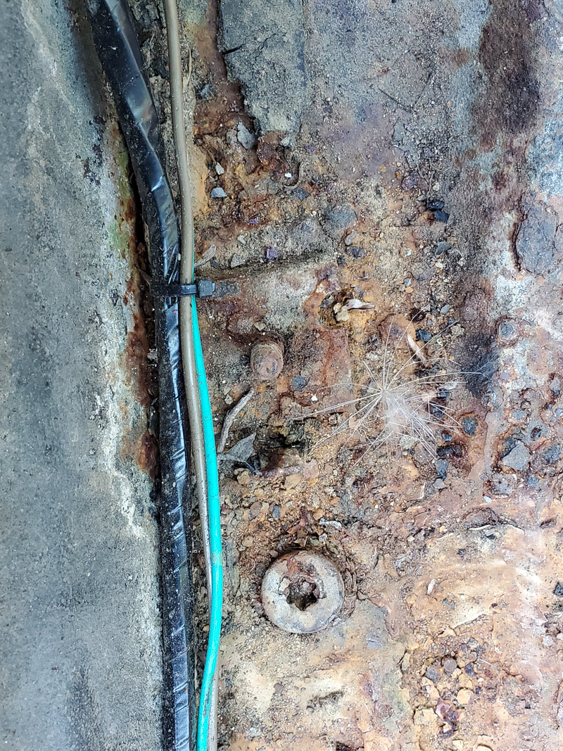
Old mounting bolt frozen in place, bolt is a torx/star head. This bolt is not coming out. A plate of some sort will be welded behind this frozen bolt to serve as a new mounting point and a hole drilled for a new mounting bolt.
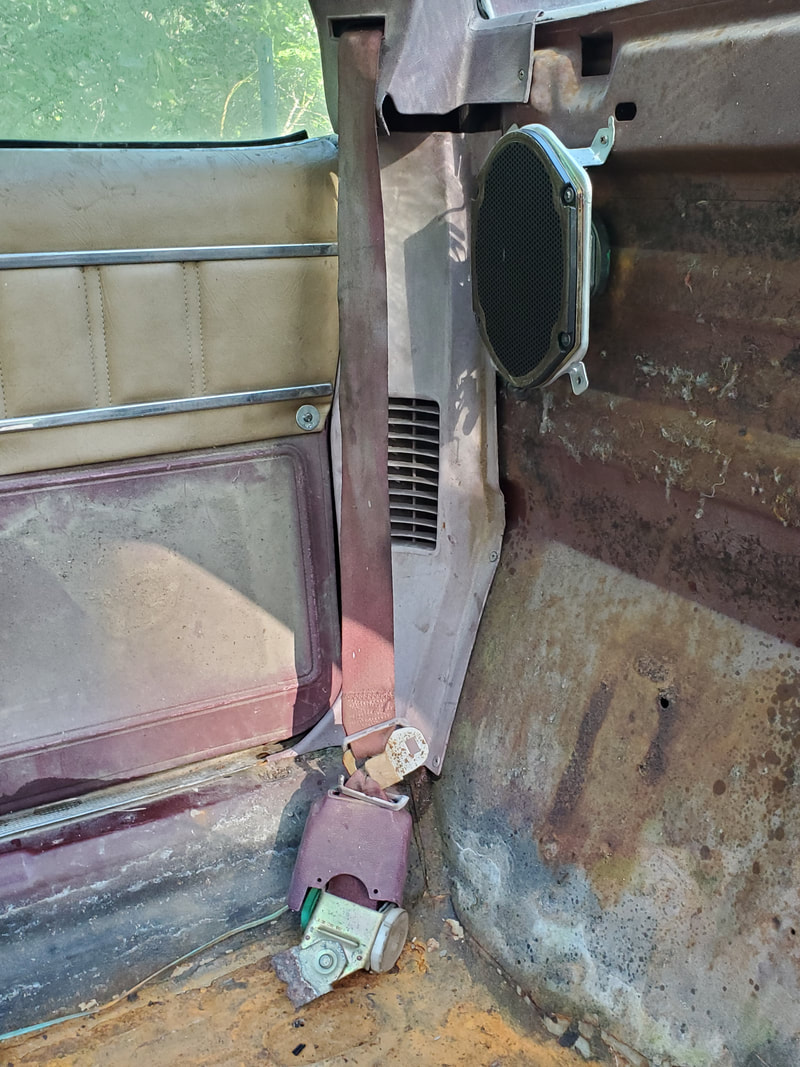
Passenger side upper reel mounted in place with panels reinstalled in place. Note the broken mounting tab on the lower reel.
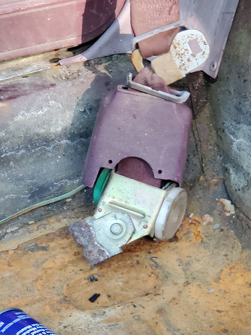
Closeup of the broken mounting tab. Extra metal of some sort will need to be welded to this broken tab, most likely a large washer that is thick enough to be strong as well as large enough to take the place of the broken metal while having a large enough hole for a new mounting bolt.
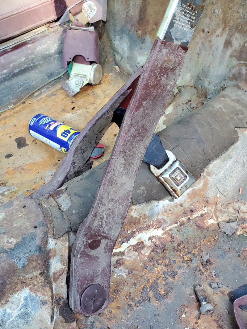
Female buckle assemblies bolted in place to the center hump. Both buckles work properly after wetting one of them with WD40.
Giving it one last shot, I put the star bit on a breaker bar and wet the stuck bolts on the floor with WD40. This turned out to be enough to allow me to break the bolts free. The threads weren't in that bad a shape so I knew I would be ok. I bolted down the driver's side lower reel but I still had to fix the broken end on the other lower reel. I welded on a large washer, probably a 5/8 or 3/4" washer. I had to match the angle of the mount on the other reel so once I welded everything I was able to bolt the other lower reel to the floor. With that done, I had to figure out the seat situation. The seats I had were a pair of VW beetle seats with a mount that was shaped like a T. Since this mount wasn't really usable in its original state, I had to figure out an alternative. That alternative was using the seat frames from a pair of seats we pulled from the minivan. These frames were narrow enough to fit under the seats so this option was the best one.
I had to cut off some metal from the arms of the T on the VW seats since I needed to expose the straight bar of the T. From here I took the rear bolt holes on the minivan frame and lined them up on the T then drilled two holes to secure the rear of the minivan seat frame to the arms of the T, at the back of the VW seat. Afterward I took a channel metal bar from the scrap pile and drilled a hole a couple inches from the end. I bolted this to one of the front holes on the minivan seat frame. I then measured the gap between the rear of the seat rails then duplicated the spacing at the front of the rails so I could drill another hole through the channel metal bar to allow me to secure it to the other front hole on the minivan seat frame. With the bar secured to the front of the frame, I trimmed the ends to make the bar fit flush to either side of the minivan seat frame. Lastly I trimmed a notch in the bottom of the T. After working the seat mechanism to slide the bar into the notch, I welded the two pieces together, fully securing the bar to the T. With that the minivan seat frame is secured to the bottom of the VW seat. After test fitting the seat, I found the minivan seat frame had the seat too high in the car. The eat barely fit because of this and would've had my legs too high relative to the steering wheel. This means having to trim the sides of the seat frame then rewelding the two halves together to make the minivan seat frame be shorter. Hopefully this will be enough to make the seat fit properly. Worst case is removing the head rests to make the seats fit better and hopefully not have our heads hit the ceiling or still have the driver's legs be too high relative to the steering wheel.
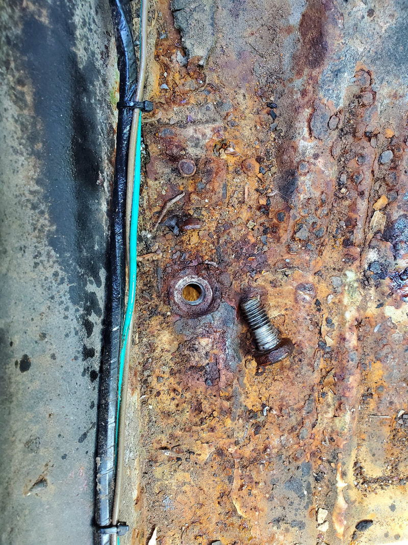
The once stubborn floor bolt now free, threads aren't that bad.
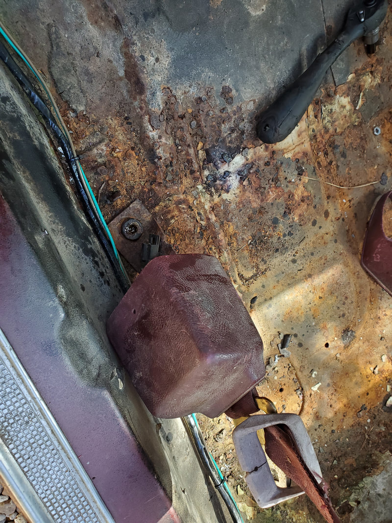
Driver's side lower reel bolted to floor.
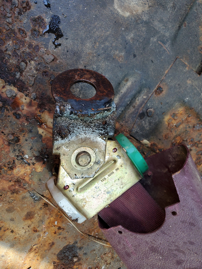
Large washer welded to end of lower reel's mounting tab. Note the angle that had to be achieved in order for this to work.
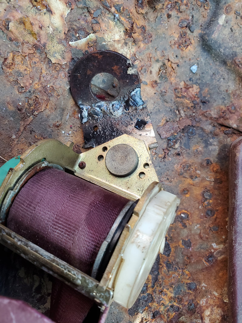
Another angle to the washer welded on to the stub of the mounting tab on the passenger side lower reel.
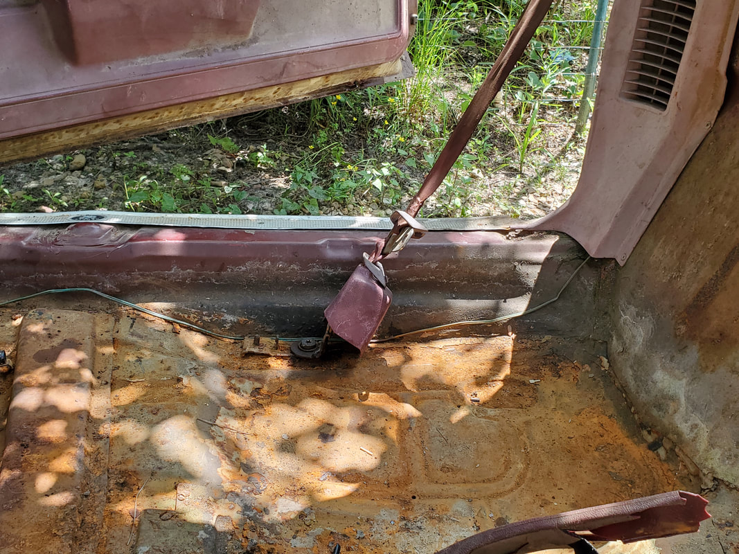
Passenger side lower reel bolted to the floor.
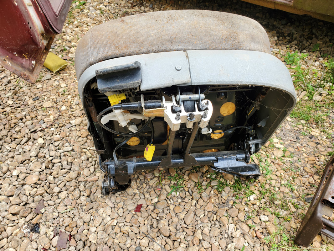
he T shaped seat frame on the VW seat, hardly anywhere that can serve as a suitable mounting point.
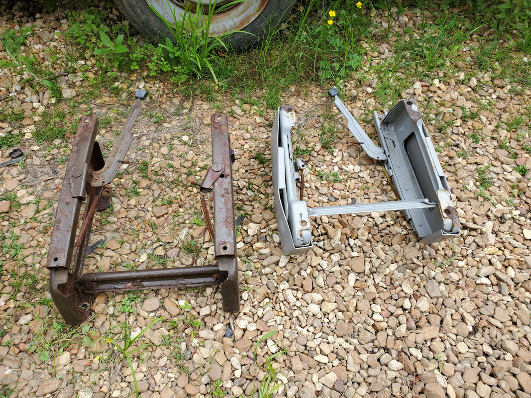
The two minivan seat frames salvaged from the two front seats. These two seats were pretty much shot so there was no real loss from taking the mounting frames from a pair of bad seats.
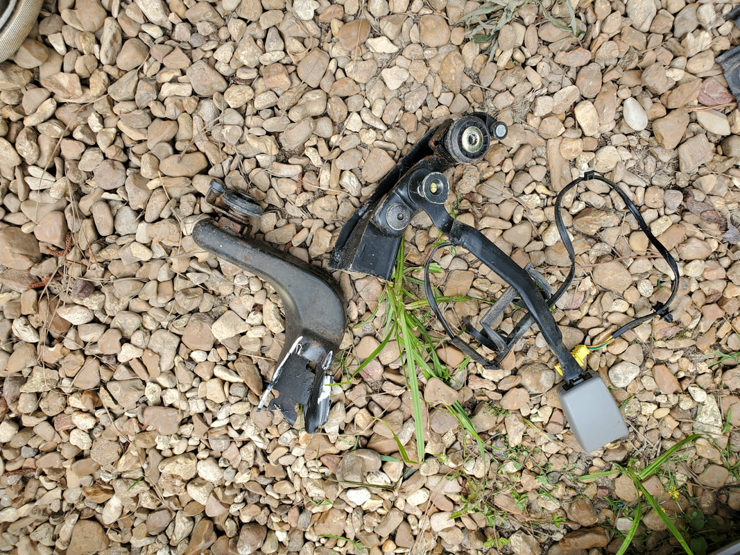
Hardware that was cut free from the arms of the T on the VW seat frame.
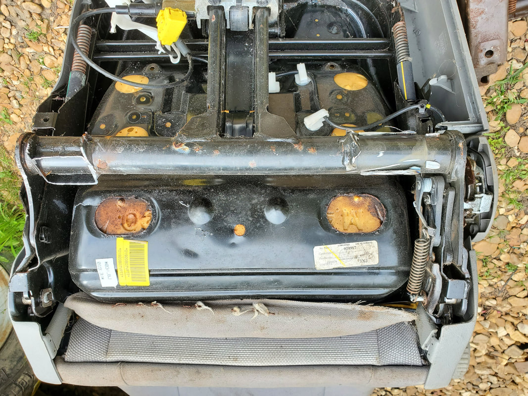
The arms of the T, now exposed enough to move on to the mounting of the minivan seat frame.
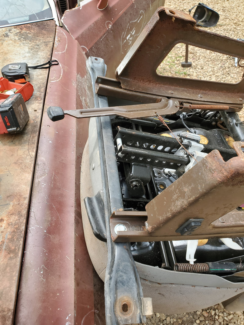
Attaching channel metal bar to front of seat after getting proper spacing between the seat rails at the front.
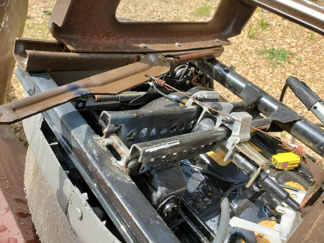
Middle of channel metal bar welded to bottom of the T on the front of the seat.
After getting this seat frame arrangement done, I tried to test fit the seat. Of course, the seat ended up being too tall, barely able to fit in the cab. Sitting in the seat wasn't an option. What this meant was the idea I'd have to do some more surgery to the minivan frame to make it shorter to allow the seat to ride lower. In my first attempt I chopped the sides in half, removing the center sections at the front and back of each side, then rewelding the two halves together. This iteration of the minivan seat frame was still too high. I cut everything apart and sandwiched the two halves together and welded everything up. the bar at the rear of the frame was cut in half and one end shortened a little then rewelded back together. Reassembling the modified (again) minivan seat frame and bolting things back, I tried again. It still wasn't quite low enough. Last thing I could do was cut notches into the arms of the T to fit the frame rails. After cutting the notches, I laid the frame rails down and installed shorter bolts through the holes, making up for the idea that the longer bolts aren't needed to go through the wider tube of the arms on the T frame. With that, I was able to get the seat lower enough that when I test fit the seat, it sat low enough that I was able to sit in the car and not have the steering wheel touch the top of my legs. I had the steering wheel at about half tilt. I reclined the seat some to get a more comfortable posture but even with the seat back at about a 95 degree angle, my head still had some clearance from the ceiling. At the reclined angle that would make me more comfortable, my head had several inches clearance from the ceiling. With that seat completed, I duplicated the same thing for the passenger seat. With both seats ready, I laid the seats on the floor, marking and drilling the holes to mount the seats. Even after drilling the initial set of holes, I still had to drill a couple new holes due to the real position being a little offset from the first hole. I had to use a large nut as a spacer on one corner on both seats to level the seat once the nuts and bolts were applied. Once the bolts were tightened, I was able to sit in both seats and make final adjustments for comfort. With the seats mounted and adjusted, I can finally write off the whole seat fiasco.
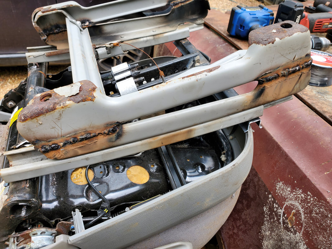
The first version of the modification of the minivan frame where the two halves were cut, and the middle section cut out prior to rewelding back together.
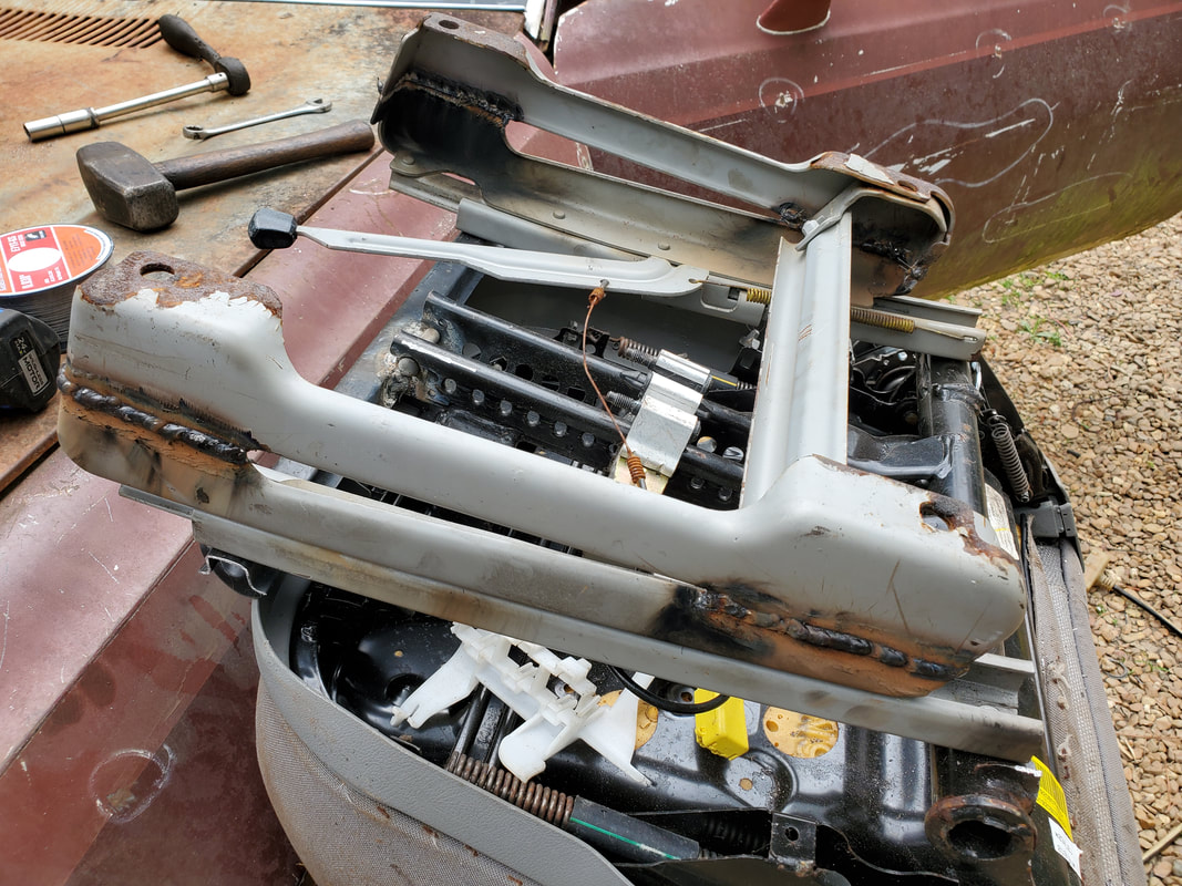
Another angle to the first mod of the minivan frame.
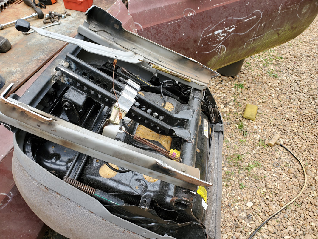
Cutting the halves of the sides of the minivan frame out after the failure of the first modification.
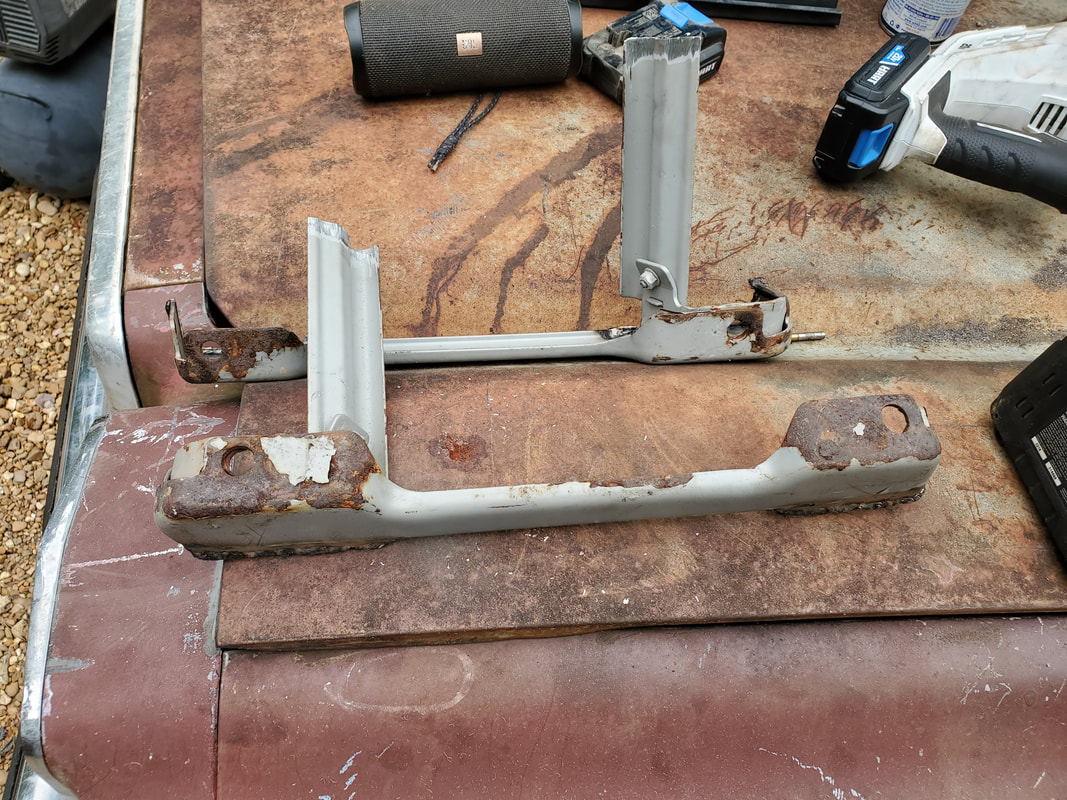
The two halves cut free from the base halves of the minivan frame. Note the bar is also cut in half for trimming down.
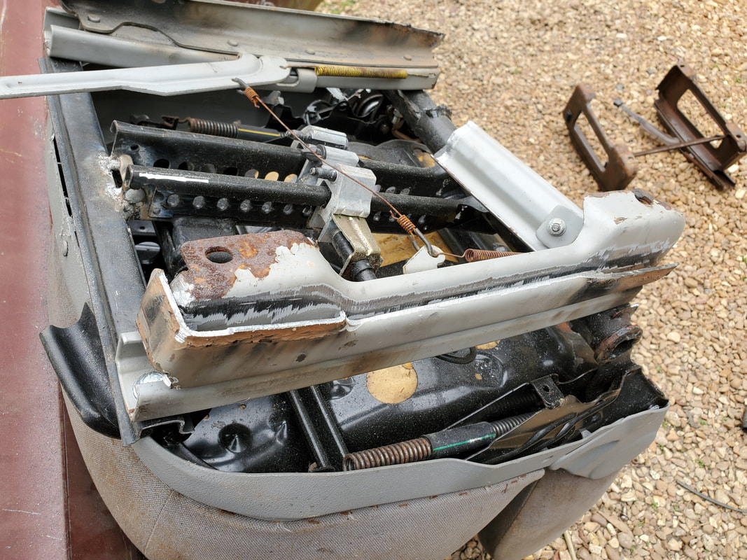
Sandwiching the two halves together prior to welding together in what will be the final modification to the minivan frame.
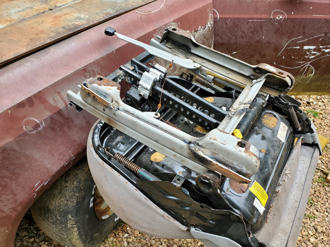
Tack welds on the sandwiched frame halves prior to first fitting. Note the bar is also trimmed down and welded together.

Notches cut into the arms of the T frame with the frame rails of the minivan seat frame resting in place.
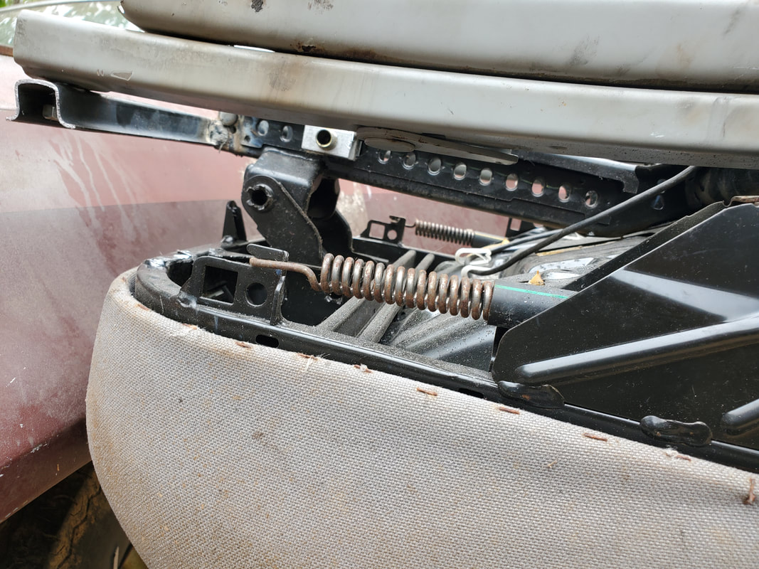
Old seat slider lever cut free from the seat and the cable removed.
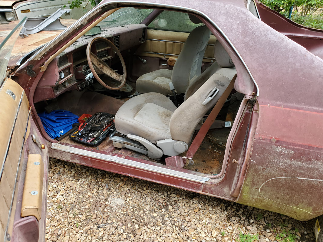
Driver's seat test fitted prior to final welding.
Passenger seat frame prior to cutting off pieces that were in the way.
Modified minivan seat frame made from 2nd frame. The final version was implemented on this frame right from the start.
Notches cut into the arms of the T frame, right from the start after cutting off the other pieces of metal from the frame.
Ends of the minivan seat frame rails bolted in place in the holes drilled after cutting out the notches. Bar was also trimmed and welded back together.
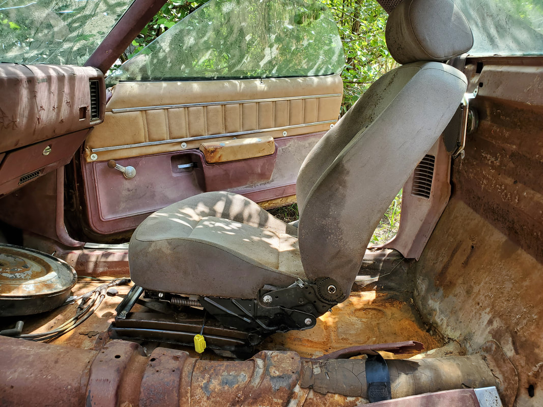
Passenger side seat bolted to floor after drilling holes an dadding nut for spacer on one corner.
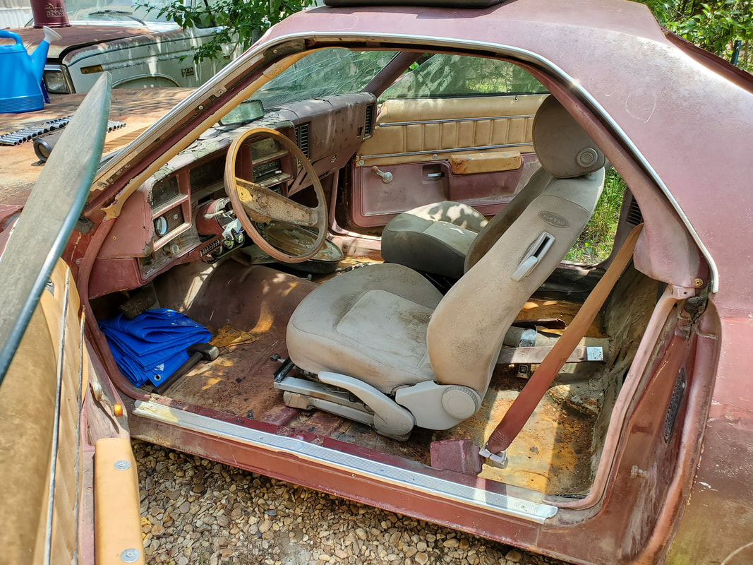
Driver's seat bolted to floor just like the passenger seat. Note the angle of the seat backs on both seats, adjusted for the optimum comfort of my frame, and probably for anyone else sitting in these seats.
With the seats in place, I took care of another small thing, which was connecting the wires from the oil and temp gauges to their respective sensors on the engine. I had already added wires to the gauges themselves and routed the wires through the firewall prior to doing all this work so when the work was done, all I had to do was connect the wires. The oil pressure sensor that came with the gauge set used 1/8" NPT thread but the fitting in the back of the block that normally holds the oil pressure sensor is 1/4" NPT thread. I'll need a 1/4"- 1/8" NPT reducer bushing to be able to attach this oil sensor, so for the time being all I could do is crimp a connector to the end of the wire and stage the sensor on the intake, just to keep it out of the way. As for the temp sensor, I routed the wire around to the sensor that I believe is the temp sensor, on the side of the block, and crimped a connector to it to attach the wire. I think this sensor is the temp sensor, as there is a temp sensor in the thermostat housing, so I'll only know if I take the sensor out and water comes out of the hole after filling the rad with water. We'll get back to that later. I also crimped a connector to the wire that will feed power to the distributor. Only other wire remaining was that for the starter, which cannot be accommodated since we don't have a starter in place. Another thing I took care of is covering up the carb port so water or other foreign matter can't enter. I also covered the thermostat port since I still have to add one, along with a fresh gasket. Lastly, I cleaned out the bed, getting the mulch out along with a couple seat bases (which are on ebay since I don't have the original swivel seats they went to). Some other parts like the emblems were moved to inside the car or safe storage. All that's let in the bed is one of the AC hoses, which I want to hang on to or when I do manage to get the AC system reassembled. At this point we've gotten as far as we could go, we will need to buy another batch of parts so we can get even further into the advanced stages of this build.
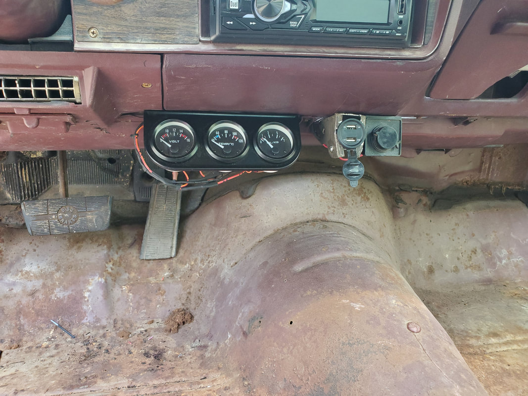
Aftermarket gauge cluster installed under the dash, note the wires just underneath the cluster, routed through the firewall for the sensors, along with the lights and power.
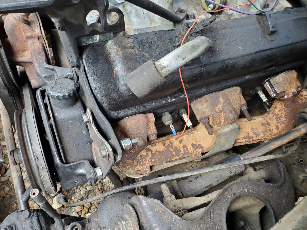
Wire routed over to what I hope is the temp sensor. I'll find out when I fill the cooling system with water and remove the sensor. if water comes out, then it's a temp sensor.
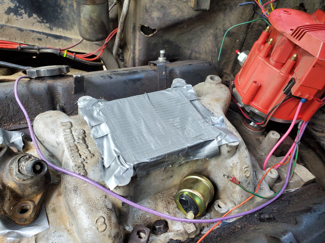
Green/red wire at right with terminal crimped on is for the oil sensor. Sensor itself is sitting on the intake, awaiting a bushing to allow me to attach it to the fitting just under the distributor, partially visible among the wires at the right. Also note the tape over the carb port and thermostat port.
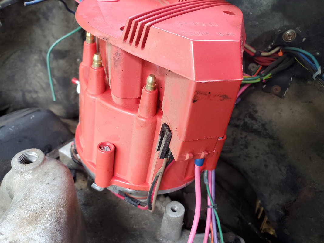
Wire hooked up to distributor for power. When a tach is installed, I'll have to run another wire out through the firewall to plug up to the tach terminal on the cap.
Bed cleaned out, leaving just the AC hose, which will hopefully be hooked up at a later date when the AC system is rebuilt.
After a year hiatus from this project, I relit the fire to try and complete this car. Where I left off, I have to get everything associated with the engine put together, install a shifter, exhaust system, then the brakes and suspension. I started off things by installing a B&M shifter that I pulled from the Rustang when I changed it from automatic to standard transmission. In the process of installing the shifter, I had to replace the cable, as it broke in the process of me trying to get the linkage bracket dialed in on the transmission. After wrestling with the bracket and the cable, I finally got the shifter straight enough to cycle all the way through from park to 2nd gear, since this is a 4spd transmission and the shifter is for a 3spd. After the shifter I picked up a thermostat and gasket along with radiator hoses so I can assemble that stuff on the engine. I took a ride to the junkyard and grabbed a starter from a late model SBC Vortec V8 engine, so its the high torque smaller starter, which I like. I had to make a power cable for the starter to install that and get it hooked into the wiring. I may end up making a better cable once I get some terminals and a heavy duty crimper, but until then I will stick with what I have. As for the exhaust, I had to get some universal exhaust pieces and start off at the flange pipes coming from the exhaust manifolds. I grabbed some 45 degree elbows, flared couplings, regular couplings and straight pipes, along with a couple mufflers and runs of pipe I dug from my scrap pile. After a little run in with my welder that required a field repair, I was able to weld up a 45 degree elbow assembly that was trimmed to fit on the flange pipe on the left side and sit with the bottom end horizontal with the floor, aiming straight back. The elbow assembly has flared ends on both ends, with the inner end welded to the short flange pipe on the exhaust manifold, with the other one open so I can slide a straight run of pipe into the end to further assemble the exhaust system. Once I get the right side done in the same way, I can then do a mock up of where the mufflers will go, based on the location of the muffler valleys, so I can see just how much pipe I need to cut and/or weld up to couple the mufflers to the elbow ends. Based on where the muffler valleys are, I may either install elbows after the mufflers and route the pipe out the sides just behind the rear wheels, or terminate the system right after the mufflers. I will have to source a couple axle pipes from the junkyard in order for me to further complete the exhaust system where it exits straight from the rear of the car.
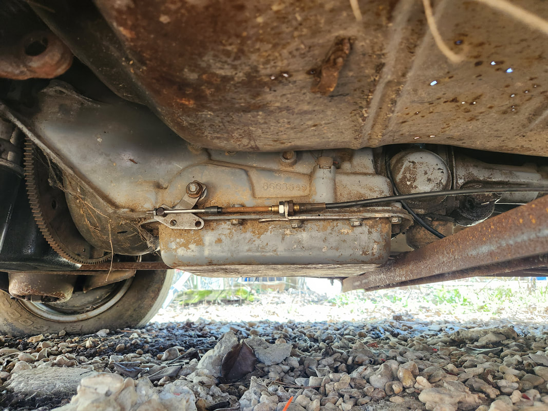
Part of the fitment of the shift cable bracket involved installing a different shift lever on the shift rod on the transmission. After wrestling with the fitment of the bracket and the cable, I finally got the whole assembly dialed in where the shifter was able to cycle the lever from park to 2nd gear.
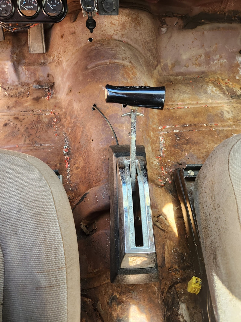
The shifter body fully installed on the center hump. Since this unit was in Rustang, the shell was trimmed at the bottom to accommodate that car's center console. As a result, there is an open space around the bottom of this shifter. Also note the cable where it is routed through the hole that was drilled in front of and to the left of the shifter assembly. The cable had to be looped around to bring it aiming forward and in line with the transmission.
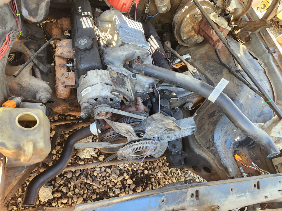
The engine with the thermostat, housing and radiator hoses installed. Radiator is still needed to help complete this installation.
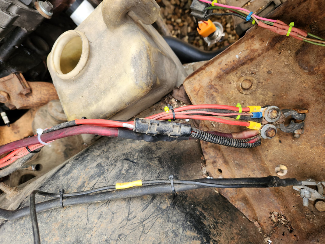
The large red cable is the power cable for the starter. This cable, once a speaker system cable, was two pieces. The looped end was spliced together with the longer length of cable with solder, then covered with heat shrink tubing. A propane torch and soldering iron helped in this work. Another terminal was crimped to the cable end then trimmed down due to the terminal having two holes on it. Cable was also routed around a spot to keep it clear of the exhaust manifold, then zip tied to the rest of the wiring to keep things neat.
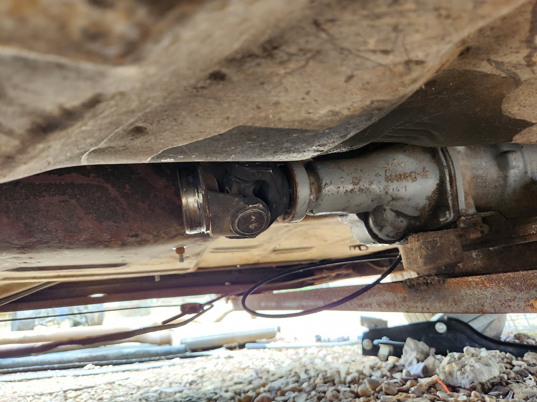
As an aside, at the junkyard I managed to find a transmission yoke, but it had to be cut off the driveshaft. The remaining tube had to be ground off, leaving just the two piece yoke and U-joint assembly. This may be the beginning to another homemade driveshaft or the pieces needed for a shop to build a driveshaft.
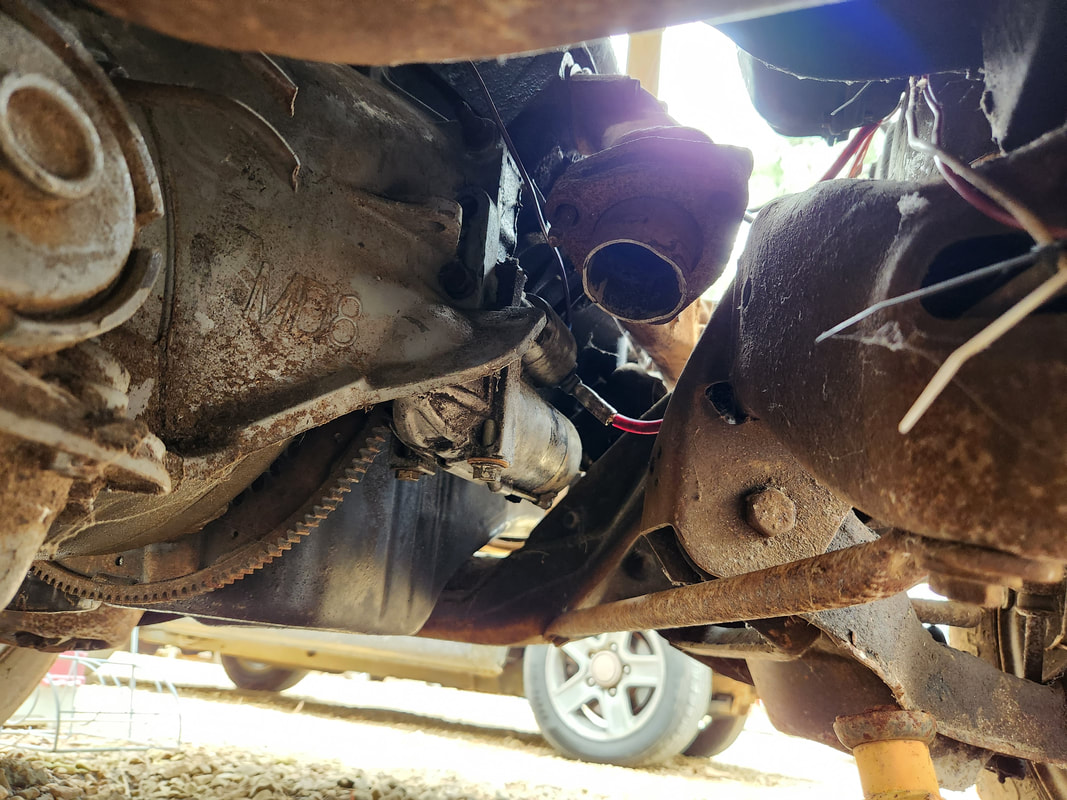
The starter is installed in place with the power cable connected, along with the wire for the onboard solenoid. Note the short flange pipe on the end of the exhaust manifold.
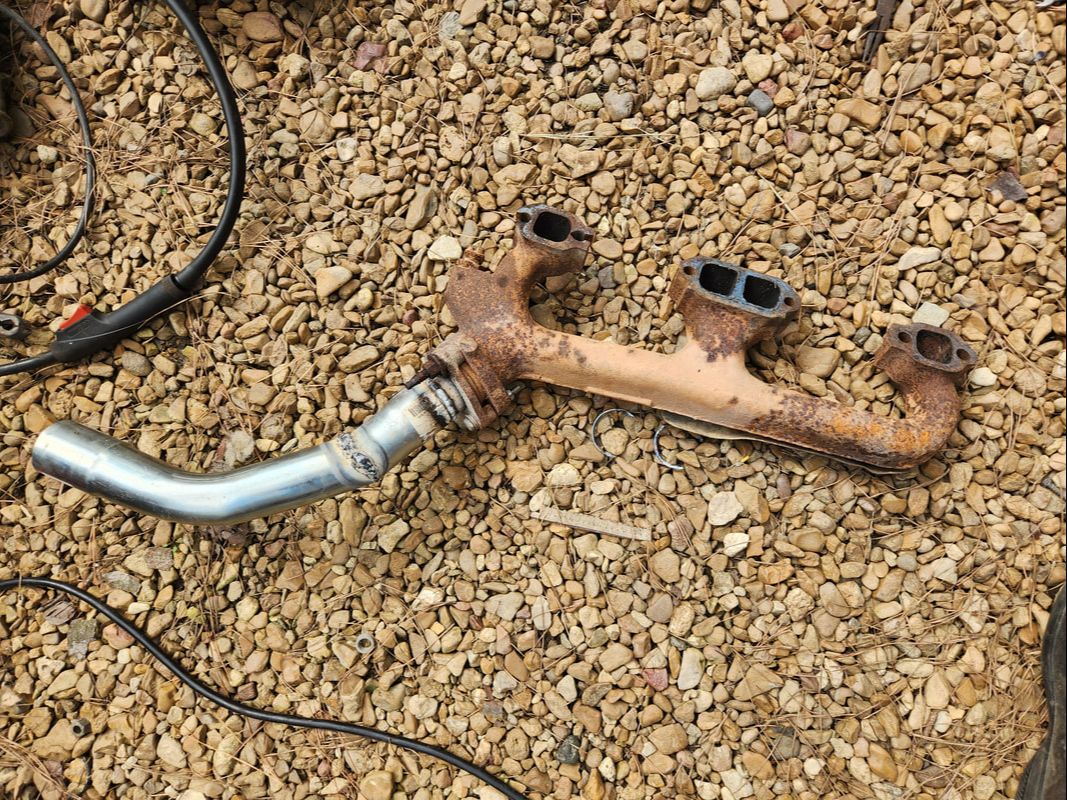
A 45 degree elbow and flared coupling are welded together to make a double flared elbow, which was then welded to the short flange pipe on the exhaust manifold, which also had to be removed to facilitate this task. The flange bolts were loosened to allow the elbow to be turned to line things up.
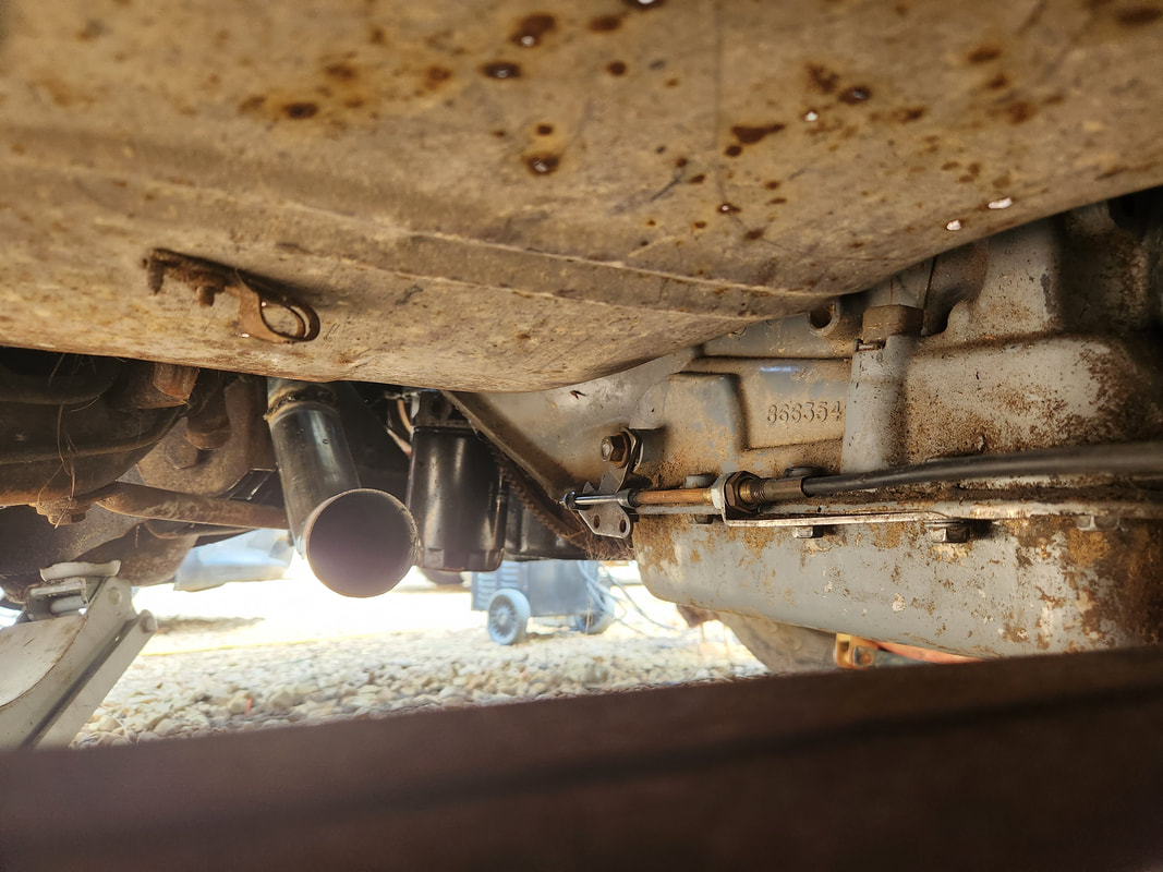
A shot from the transmission crossmember looking at the output side of the elbow after reinstallation of the exhaust manifold. After the unit was reinstalled, the pipe was turned to align the pipe straight with the imaginary line for the exhaust system. The flange bolts were tightened up to finish the work.
After getting the left side elbow taken care of, I did the same thing on the right side, including having to remove the exhaust manifold. Unfortunately, since the flange pipe had to be welded on this one due to the bolts being broken on the manifold, I had to size things up a couple times and even cut and reweld things a couple times before getting the whole assembly right enough that I could write off the "header" as complete. Next, I started making the greater exhaust system. I had to add a couple cuts of pipe that were shaped in a bit of an S configuration, allowing the muffler to sit in the muffler valley while the pipe is able to angle down and level off and run straight along the bottom of the floor to the elbow. On the left side I had to add another S-pipe to angle up slightly to go straight into the left elbow. The hanger, which at first would be attached to the rear of the muffler, was moved to the front of the muffler, as there was no solid spot to drill a hole through to secure the hanger at the rear of the muffler valley. After hanging the hanger up on the left side and fully securing the whole of the left half of the exhaust system, I added a slight weld to hold things together so I could put a clamp on to crimp the flare on the elbow. On the right side I only had to add one S-pipe at the muffler but still had to test fit the system to see how much pipe I would have to add at the front. In this case a short piece of pipe was all that was needed to couple to the elbow. With a slight angle added, I welded the short pipe in place then installed the system. I attached the hanger with another bolt, washers and nut as on the left side. To reach the bolt I did have to cut a large section of the rear panel out, opening up the dead space in the trunk area and giving me access to the area to secure the bolt. This panel I cut out actually added some more versatility to the rear space as I can now use this space for extra storage. I might even consider cutting the rest of the middle of the panel out, fully opening the "trunk" space for use.
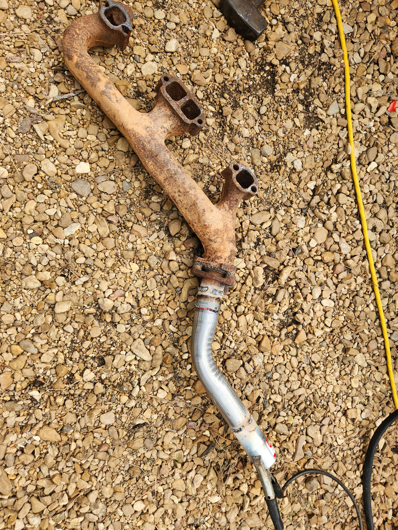
The right exhaust manifold with the elbow welded in place after multiple test fits. The flange area was welded due to the bolts being broken on the manifold so what we ended up with here was a legitimate header.
The poor man's header is mounted in place with the output lined up with the top of the crossmember, as can be seen from this angle.
The completed left half of the exhaust system, with the two S-pipes welded in place to allow the muffler to sit in the muffler valley while the pipe angles just right to run along the floor and to the elbow.
Closeup of the front S-pipe of the left half, with the short section of pipe going into the elbow flared end. Note the light weld along the bottom to hold the system in place until a clamp can be applied.
Rear S-pipe in place with muffler tucked away nicely in the muffler valley. Note the clamp and hanger in place holding the muffler up in place.
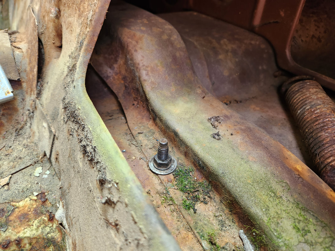
In order to secure the left half, I clamped the hanger to the front of the muffler and drilled a hole through the floor, which ended up being in the "trunk" area of the cab. A bolt with washers on both ends and a nut to hold it all together secures the hanger. The muffler is essentially hanging from the end of the straight pipe.
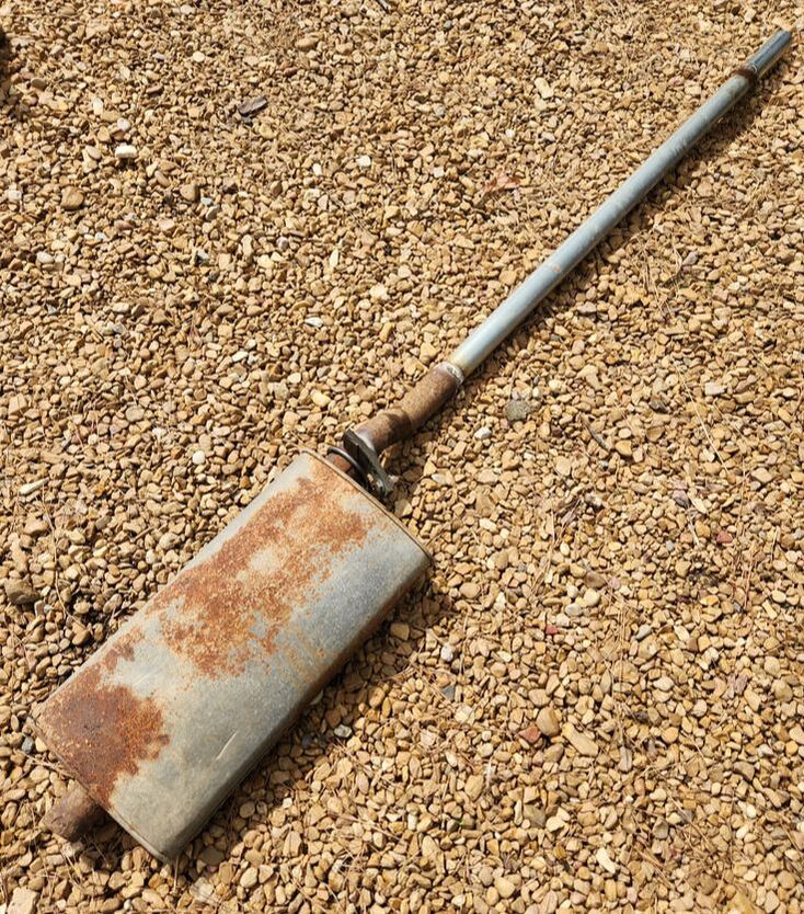
The complete right half of the exhaust system with a single S-pipe and a short piece of pipe at the front, welded in place at a slight angle to terminate at the elbow at the proper angle.
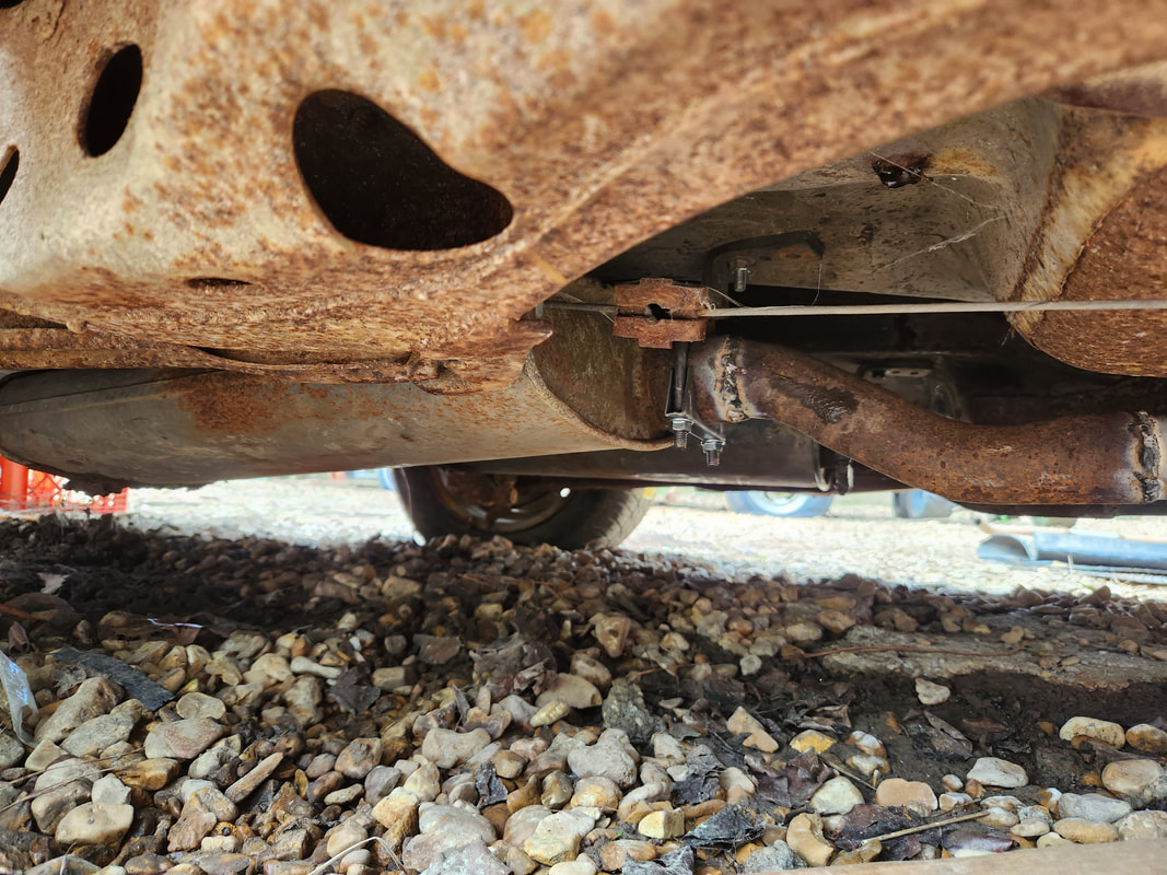
The muffler is in place in the muffler valley with the clamp and hanger in place. Later I will apply force with a jack at the rear of the muffler to straighten it out and have it rest parallel to the floor.
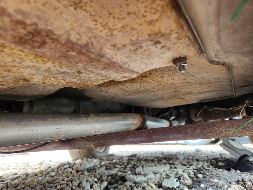
The straight pipe passes over the crossmember with the angled front section of pipe inserted into the elbow flare. A clamp is in place to crimp the flare around the end of the pipe to hold things in place, along with a light weld for redundancy.
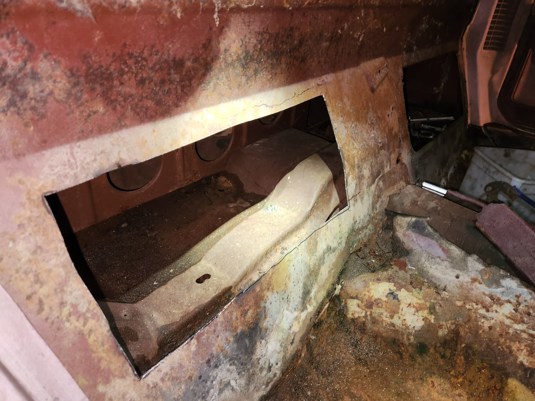
A large rectangular hole is cut into the rear panel behind the passenger seat to allow for access to the hole that was drilled to secure the bolt holding the hanger. This hole allows for more access to the dead space behind the cab, effectively doubling the trunk space. I may cut the rest of the metal out and just open the area completely for better access from left to right.
After the completion of the exhaust, I turned my attention back to the engine bay. I had to install the carburetor, which would also include the fuel line and the linkage for the TV cable on the transmission. Installation was pretty simple, just a gasket and four bolts. As for the fuel line, I took a piece of salvaged metal tubing, making sure it was clear and bent it as necessary to reach down to the front of the engine to connect to the end of the metal fuel line coming from the fuel tank. A short piece of rubber hose at both ends connected the metal tubing to the nipple on the carburetor as well as the end of the main fuel line. As for the TV cable, I had to take a carburetor throttle cable bracket and do some makeshift modifications to allow for the attachment of the TV cable. There was a small piece I had to order to secure to the throttle linkage on the side of the carburetor to allow the end of the cable to be attached. A worm clamp was used to hold the body of the cable in place. I will still have to install a throttle cable though. I also installed a wire harness, well really just a plug for the alternator. I routed the wires to get over through the firewall and to the fuse box and to the positive battery terminal, securing everything with zip ties. I also took a minute to crank the starter to find TDC on cylinder #1 so I can install the spark plug wires on the distributor so that too will be ready to go. Lastly, I took a couple moments to use some scrap metal to fabricate a couple bumper mount brackets, reinforced with extra metal and stronger welds to ensure they will hold the heavy bumper in place.
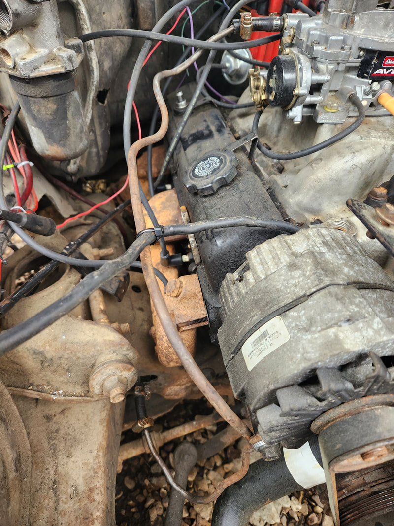
The section of metal fuel line staged along the top of the engine, routed down to the front where the main fuel line terminates at, with rubber hose on both ends to couple the metal line to both the carb and the main fuel line. Also note the ground cable that's secured via zip tie and bolted to the engine.
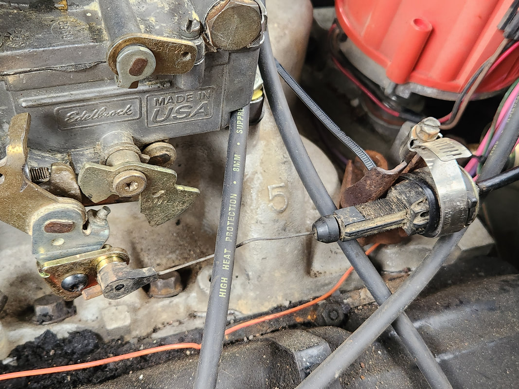
The makeshift throttle cable bracket bolted to the intake in order to hold the transmission TV cable, which is done with a worm clamp. An aftermarket piece is attached to the carb throttle to clamp the cable end in place. While factory cable brackets exist for this very application, this was made to get things hooked up at the moment, later on the proper equipment can be installed once everything else is finished.
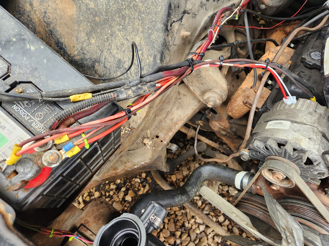
The wire harness/plug for the alternator is plugged in place with wires routed to the end of the positive battery terminal and the other line connected to a wire going into the cab and terminating at the fuse box. Note the new radiator in the bottom foreground, which was also installed.
A full shot of the carburetor, vacuum hose for the brake booster, and the spark plug wires for the distributor all hooked up. Note the top radiator hose that's installed as well.
The right side bumper mount bracket welded up with reinforcement metal and extra welds from a stronger welder to make the overall package stronger.
The left bumper mount bracket in place, bolted up at four points, one at the top and bottom and two on the frame, holding the left side of the bumper in place. Lock nuts ensure everything stays in place.
The heavy bumper mounted in place with the new bumper mount brackets underneath. The car is now complete body-wise.
On a lighter note, I did take a moment to address a few small things. I got a fuel cap and radiator cap in place. I also fabricated a retaining plate for the top of the radiator to hold it in place against the core support. This plate is held in place with self tapping screws. Another thing I added was an aftermarket transmission dipstick. This thing is flexible and bolts up to the firewall of the vehicle it's equipped in. I did have to move a couple things on the firewall to make room for the retaining bracket to hold the dipstick. In order to fill the thing I have to use a piece of heater hose fit over the top portion of the dipstick, routed under the hood and over the windshield. A funnel then allows me to fill the transmission. The last thing I did was make valve lash adjustments on the valve train before putting the valve covers down with fresh rubber gaskets. The last thing I'll have to do is add enough fuel to allow me to start the engine and tune it then run a little while to verify everything is good on the engine.
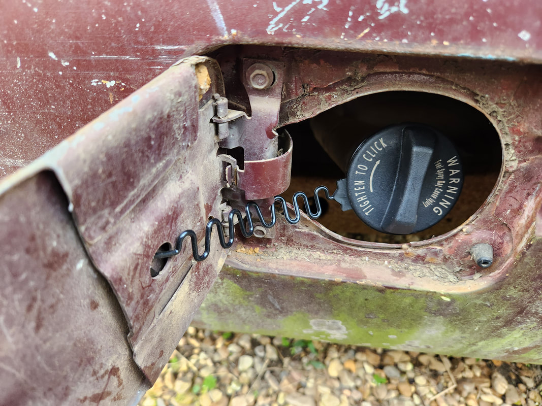
A fresh fuel cap is installed, even with a tether to hold the cap to the fuel door so the chances of losing the fuel cap are very slim.
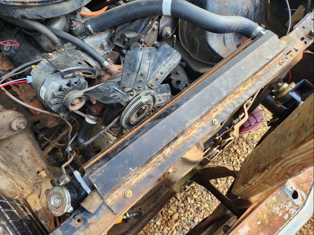
This scrap piece of stamped sheet metal was manipulated enough to fit over the top of the radiator. Pieces of radiator hose were cut and fit over the top of the rad to cushion the plate so vibrations wouldn't damage the radiator. The plate is held in place with self tapping screws. Note the fresh rad cap in place as well.
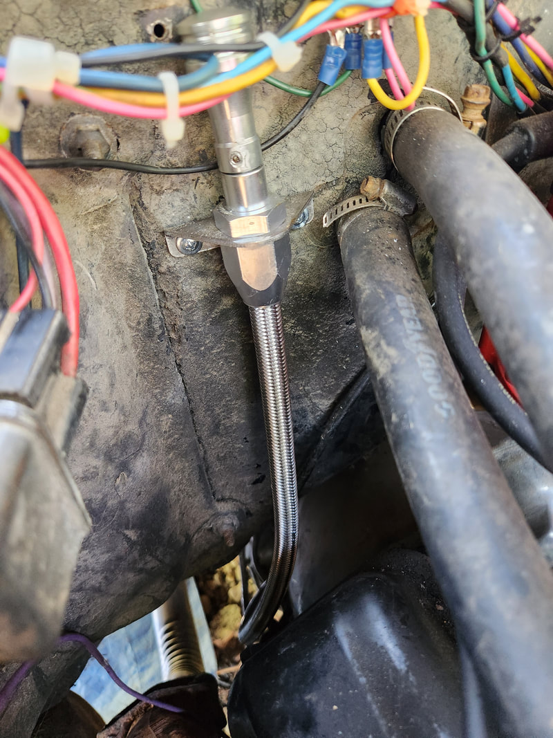
This flexible dipstick tube is installed on our transmission and bolted to the firewall. Filling this thing requires the use of a heater hose on the top portion of the tube, with the hose routed under the hood where a funnel is plugged in to fill the transmission. Note how the wiring that was already here is now in the way of the dipstick, which will make checking oil a bit annoying. Probably should've went with a stock dipstick, but then it would've required being able to remove a bellhousing bolt to secure the dipstick tube.
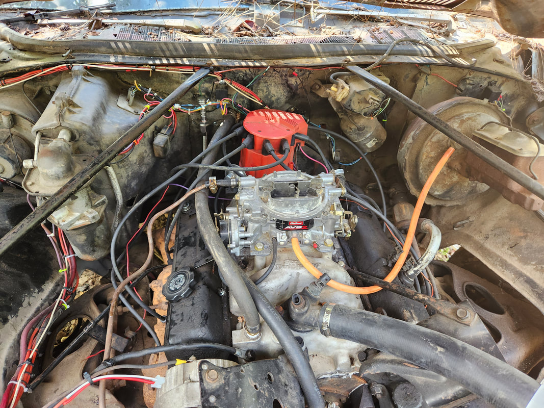
After rotating the engine until the pushrods no longer had pressure applied, I was able to tighten the rocker arm nut until there was resistance to the push rod while rotating it. While not the correct way to do valve lash adjustments, this is a quick way to at least get things set enough to run the engine.
