THE S10 RANGER CHICKEN COOP
Ranger body after removing fender on right side.
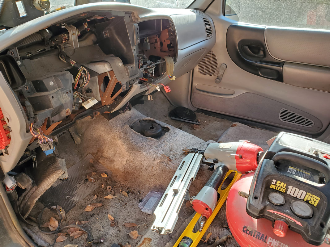
Interior after removing seats.
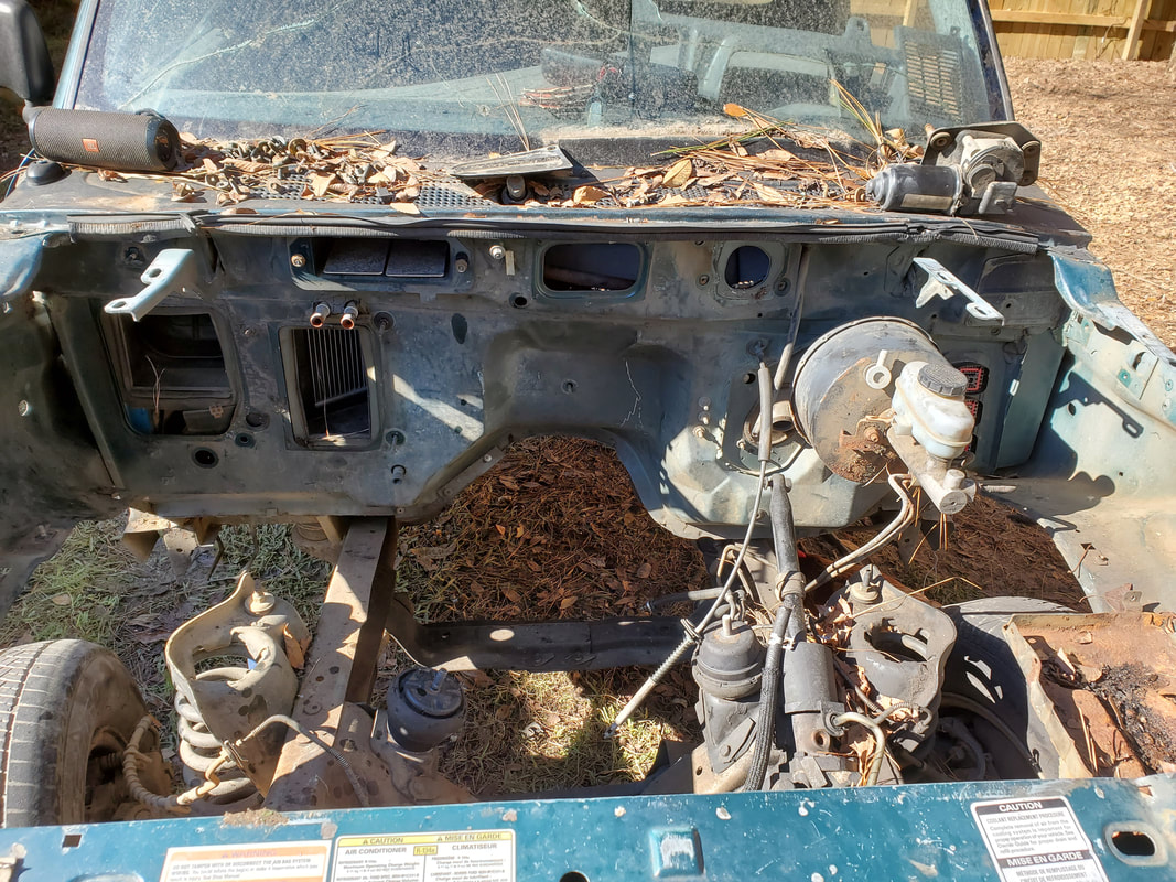
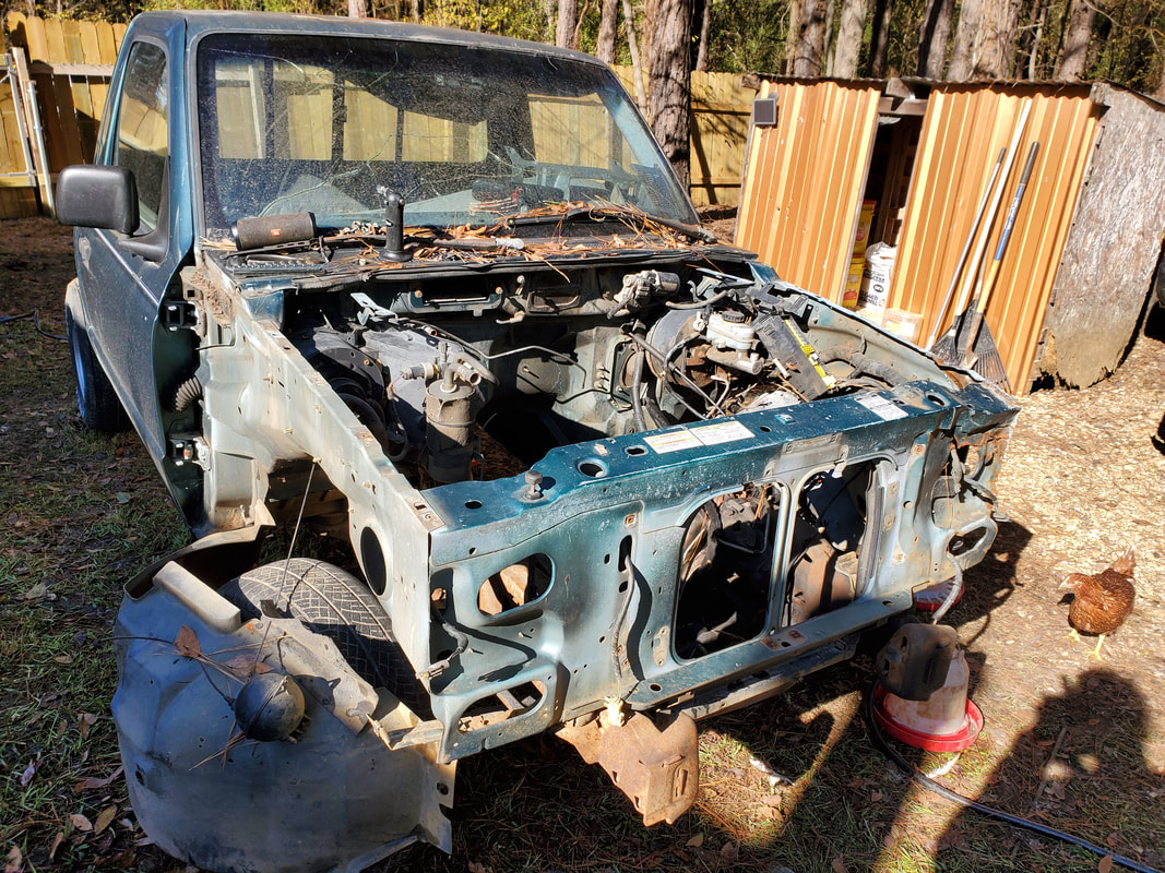
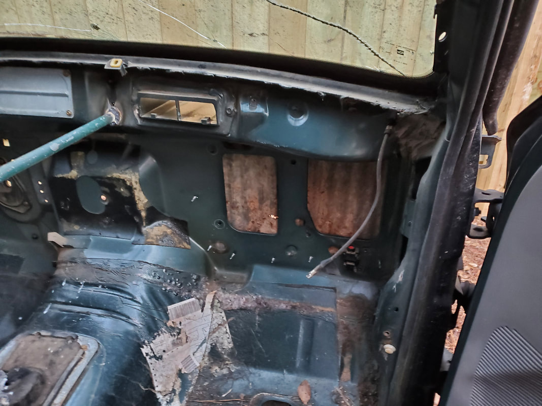
Engine bay after removing components from firewall.
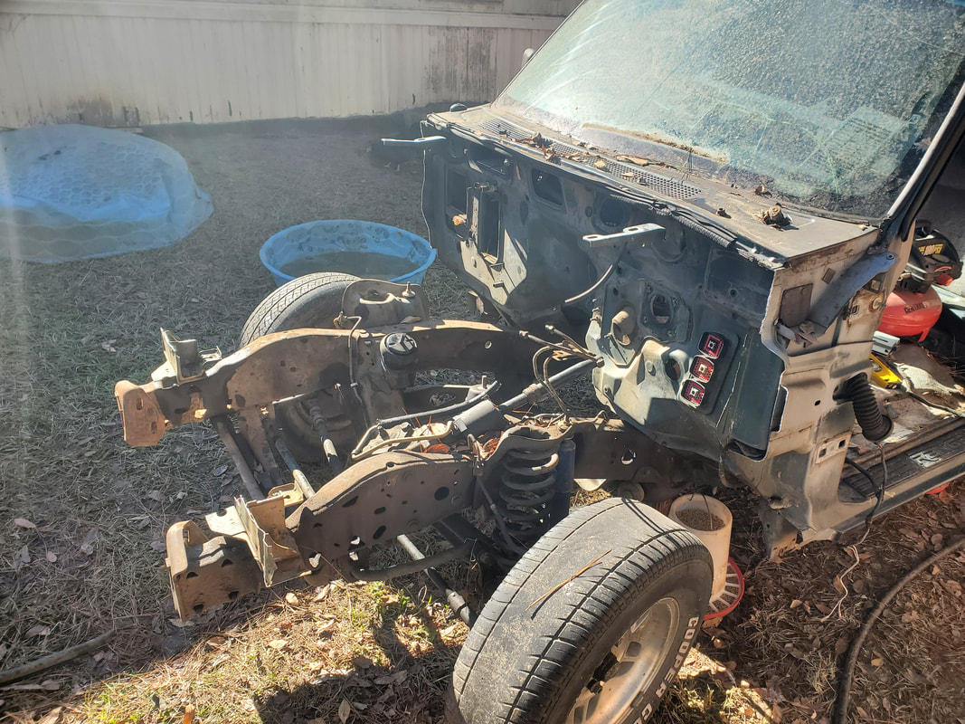
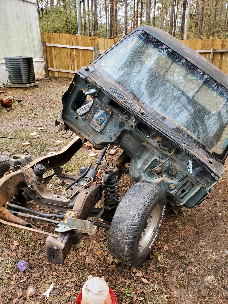
Cab and engine bay after chopping off fender aprons and radiator support subframes.
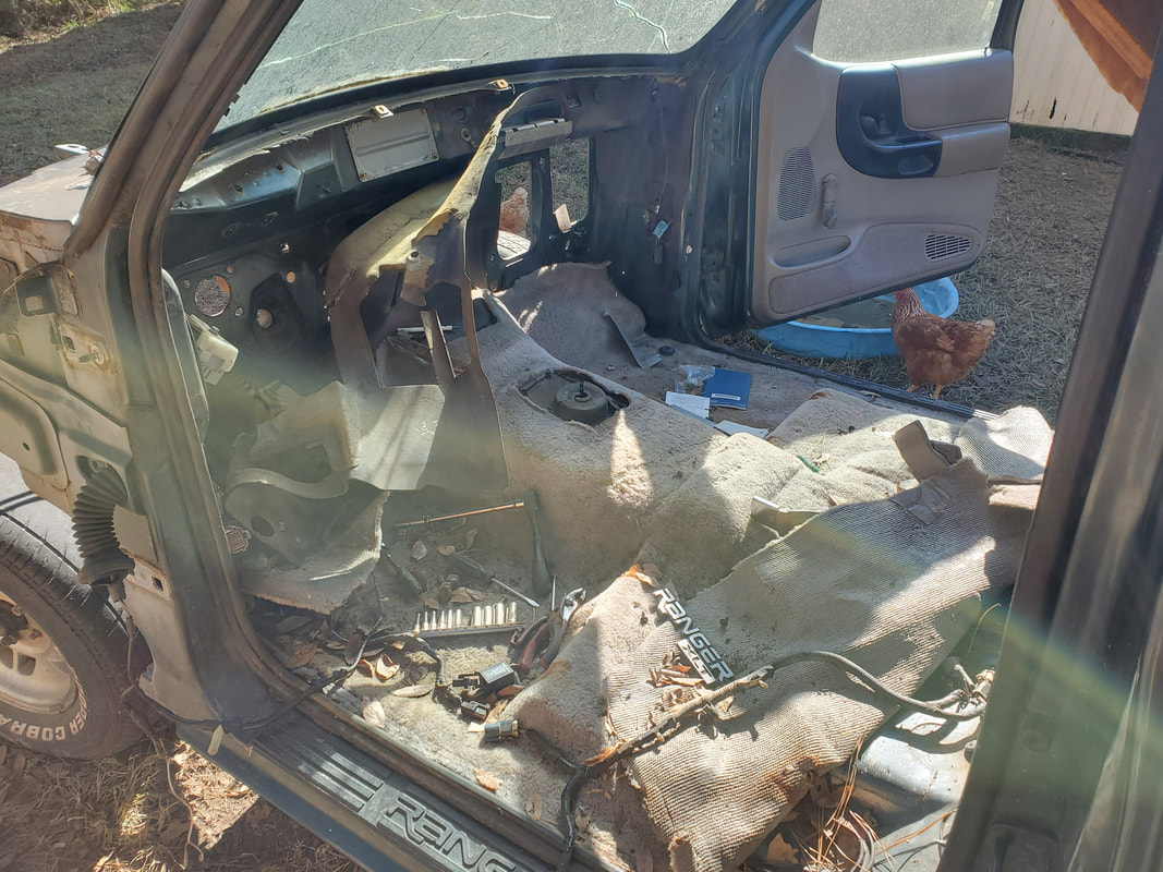
Interior getting gutted even more.
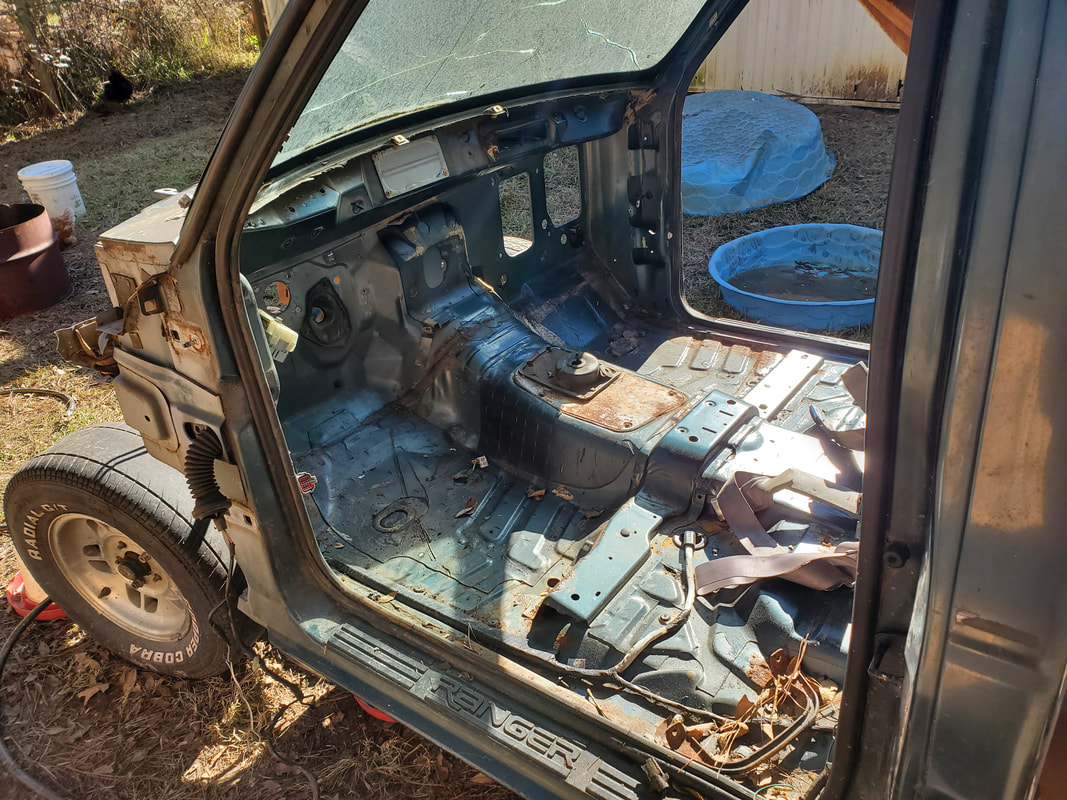
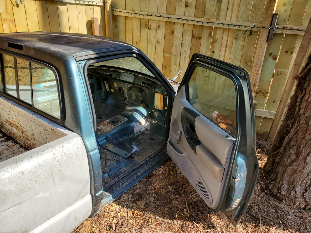
Gutted interior with door removed.
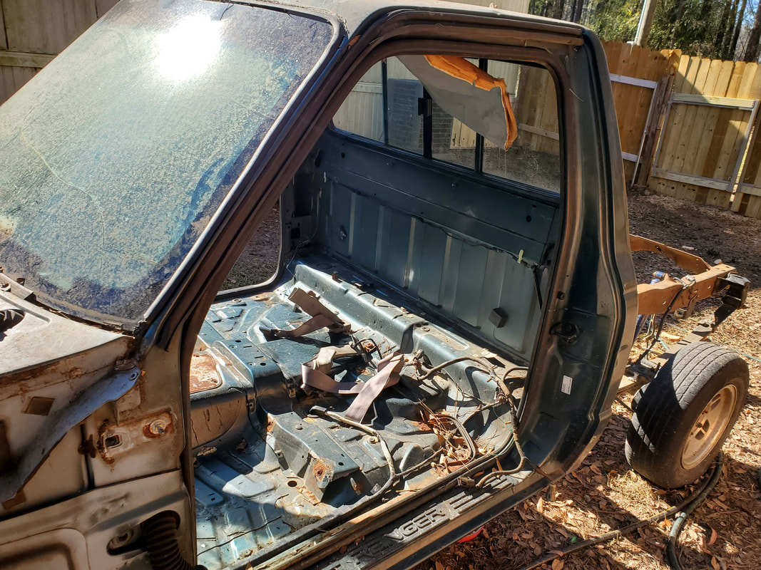
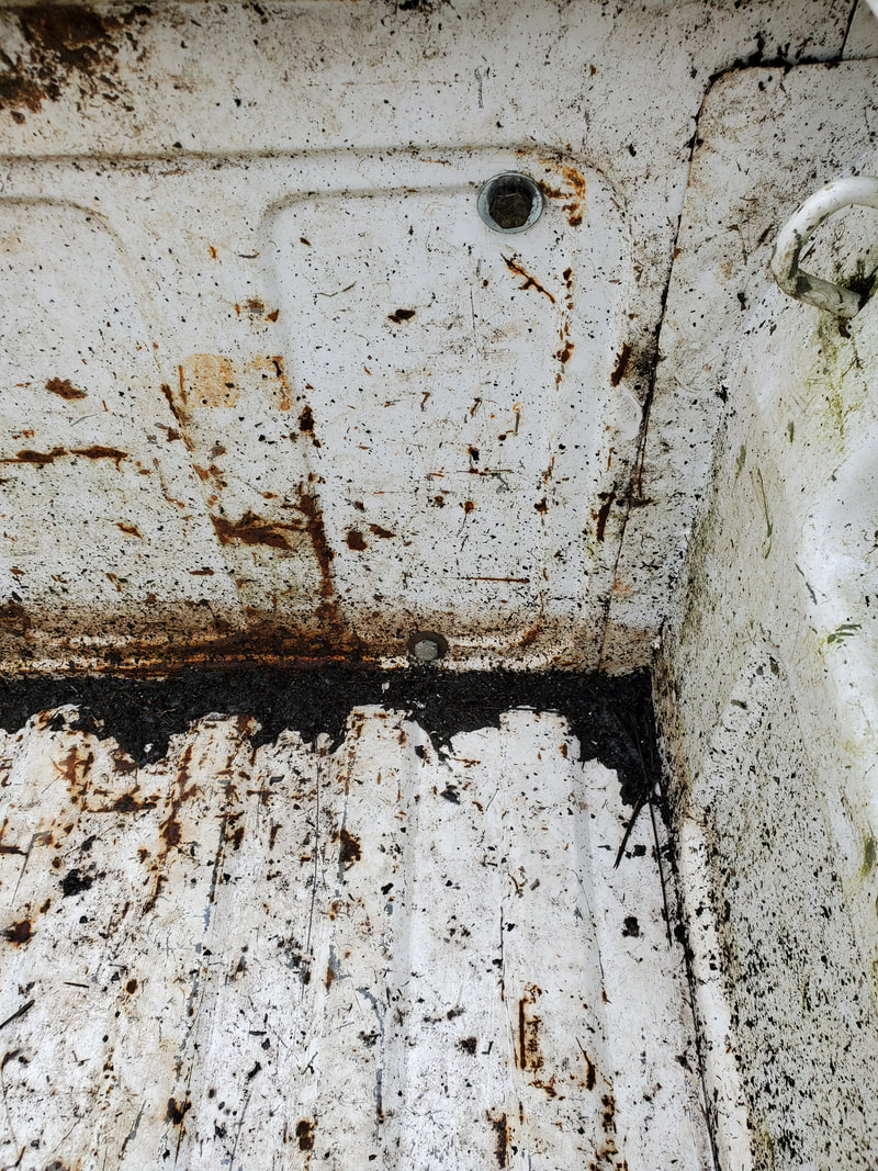
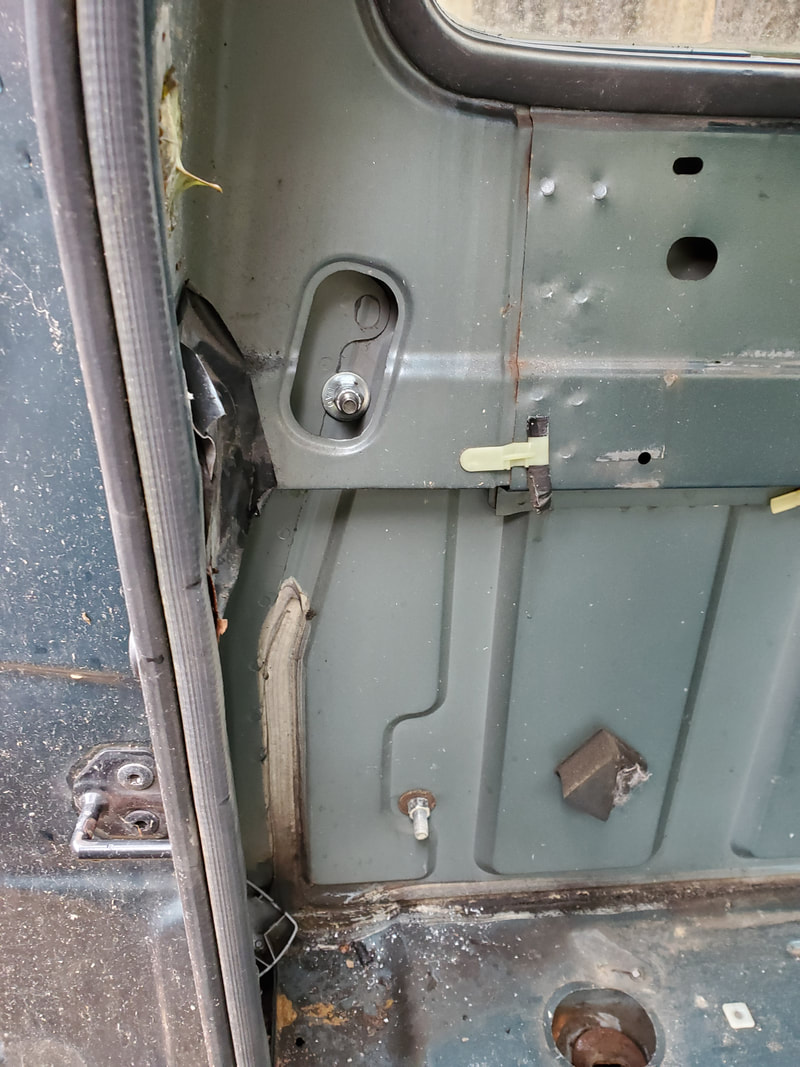
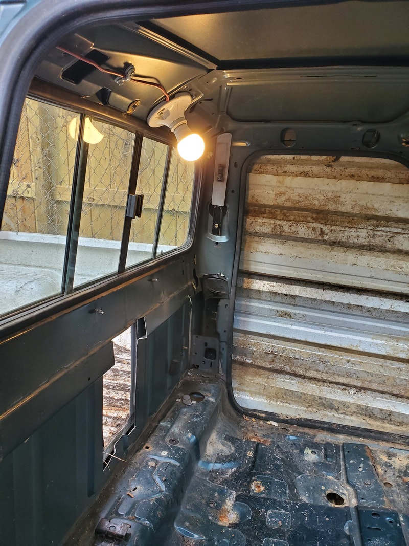
Rear of gutted interior.
With the cab gutted and every other unnecessary component removed, I started to try and remove the bolts holding the cab to the frame. Of course because this is a 25 year old truck, the bolts were more or less rusted in place. Even with the impact wrench I was unable to get these things to break. Out came the reciprocating saw and some heavy duty metal cutting blades. I slowly started cutting through the rubber bushing and into the bolt, having to pry up on the cab to take the weight off the rubber bushing. Eventually I made my way through the bolt. I had three more bolts after that. With these bolts cut, I had to enlist the help of the ole lady to help me get this thing off the frame.
We tipped the cab off to one side, leaning it on the ground. After working it free from the cab we got the two wheel dolly under the thing and slowly started moving the thing across the chicken yard over to the Northeast corner of the chicken yard. We made it 3/4 the way to the destination before getting stuck by a couple of trees. We had to take the cab off the dolly and slide the thing across the gravel over to the site. With the cab in place we tipped the thing over right side up where it will stay.
We tipped the cab off to one side, leaning it on the ground. After working it free from the cab we got the two wheel dolly under the thing and slowly started moving the thing across the chicken yard over to the Northeast corner of the chicken yard. We made it 3/4 the way to the destination before getting stuck by a couple of trees. We had to take the cab off the dolly and slide the thing across the gravel over to the site. With the cab in place we tipped the thing over right side up where it will stay.
Removing cab from frame.
|
|
|
|
|
|
|
|
|
With the cab in place the next order of business was the S10 bed. I was able to lift the thing up on its end and get the dolly under it and slowly work the thing around into the chicken yard and around another route to get it staged at the NE corner of the yard. At first I planned on using railroad ties as a foundation for the two bodies but with the bottom of the bed floor being almost a foot from the ground, they wouldn't work.
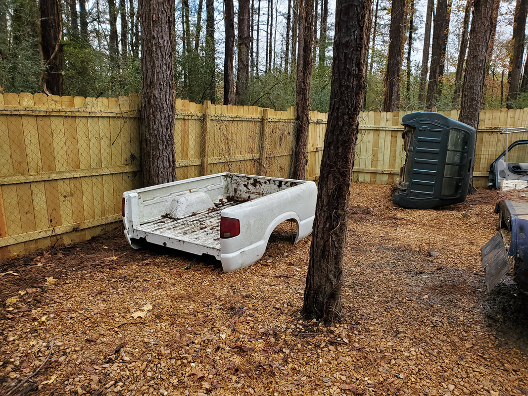
S10 bed staged at the build site, note Ranger cab on its side awaiting being righted.
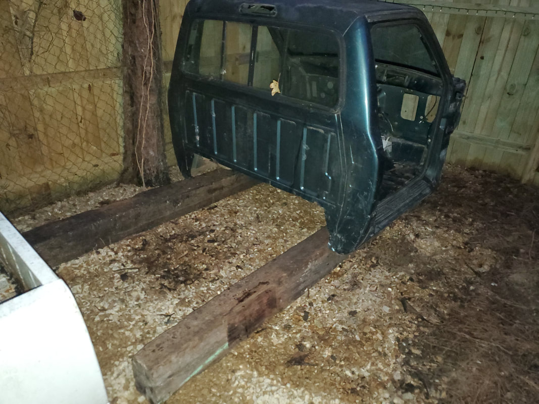
Staging cab on railroad ties with bed in foreground to left.
When we tried to put the bed on the ties, due to the spacing of the bottom of the floor, there was no contact with the ties. The cab was in a position that had things uneven. It could've worked but I wasn't satisfied when I stood back and looked at it. If you're going to do something, do it right. I made the ole lady help me move the bodies out of the way while we get these heavy ass railroad ties. Of course it sucked but that's progress. Anyway, we pushed the bed up to the cab, both units on the ground. When I got everything lined up, the two bodies looked perfect. Everything lined up just right. With that it was decided not to bother with the ties.
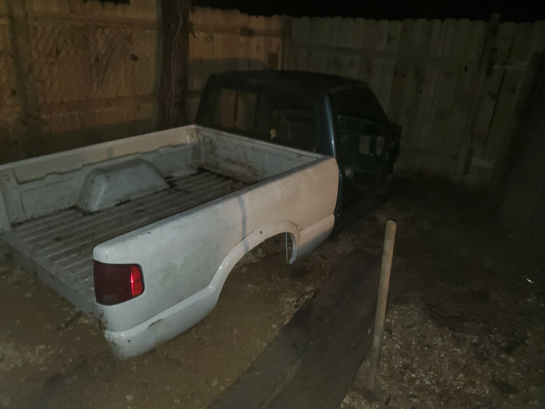
Cab and bed pushed together on the ground. Note railroad ties in foreground.
To help make things mate up even better I found that I had to put something under the front of the cab to get the front lifted up more in order to make the back of the cab mate up more flush with the front of the bed. The best thing I could find to accomplish this was bricks. I put two bricks under the mounting points on the front of the cab. These mounting points are the points where the cab was mounted to the frame. With the bricks in place everything mated up even better.
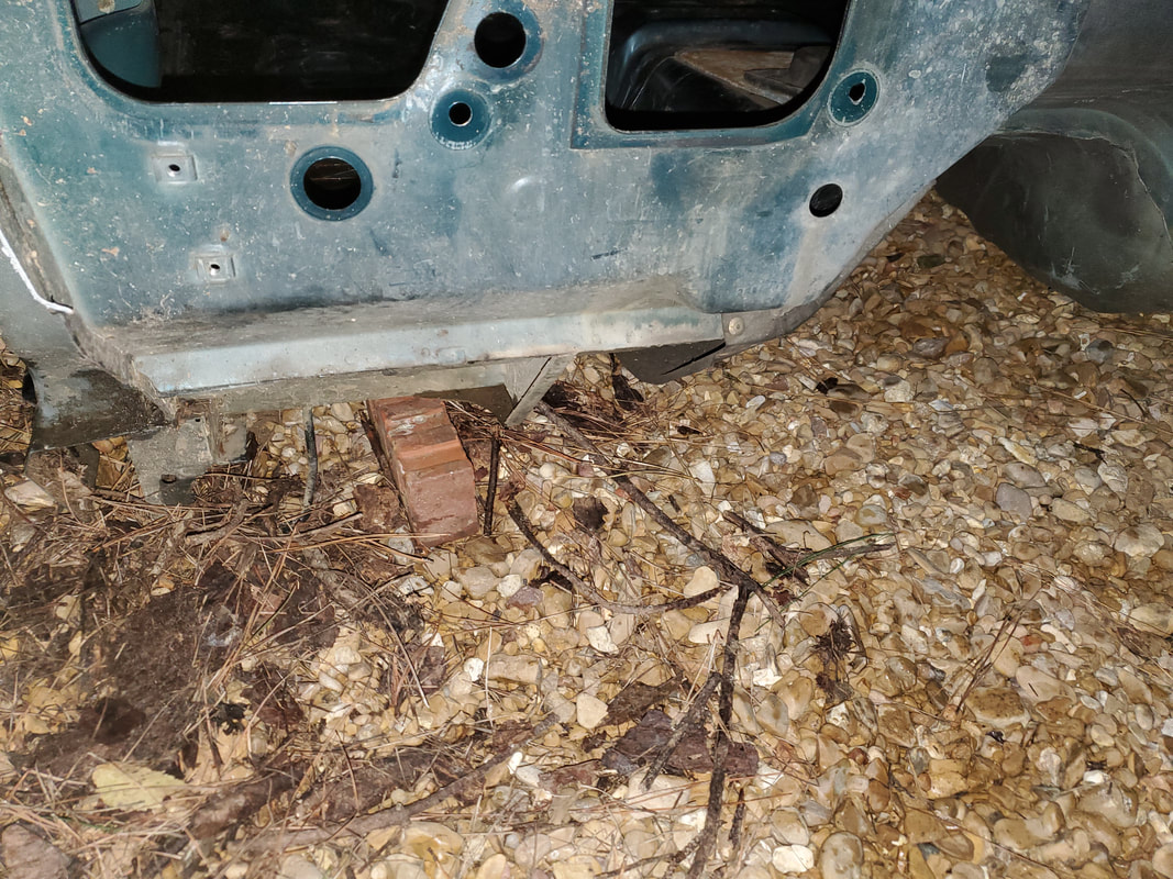
Bricks under mounting points on front of cab to help level the cab off to make it mate better to front of bed.
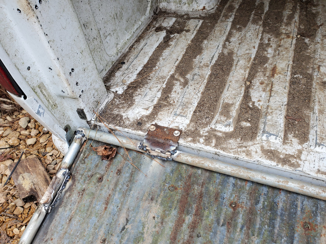
With the two bodies put together the next thing was fastening the two bodies together. This was accomplished by drilling four holes at the corners of the front of the bed. These holes went through the back of the cab as well. Long bolts with washers and nuts secured the two points together nicely. By doing this I didn't have to worry about trying to weld the two bodies together. Bolting the two bodies together was a lot neater than welding.
Bolts in place at the two right corners to hold the two bodies together.
Two bolts on right side going through back of cab.
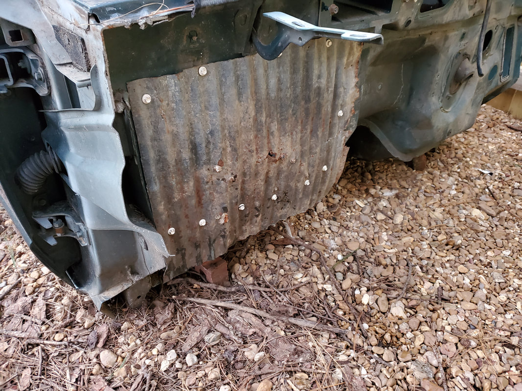
The next order of business was covering up the driver's side door opening. This was accomplished with some scrap corrugated sheet metal. Using self tapping screws I started at the bottom, laying a sheet down and screwing the panel on at the front and back. The next panel overlapped the first panel, securing with the screws. By overlapping this will allow the setup to shed water much better. After making it all the way to the top I trimmed the excess metal from around the A-pillar and hinge area to neaten the whole covering up.
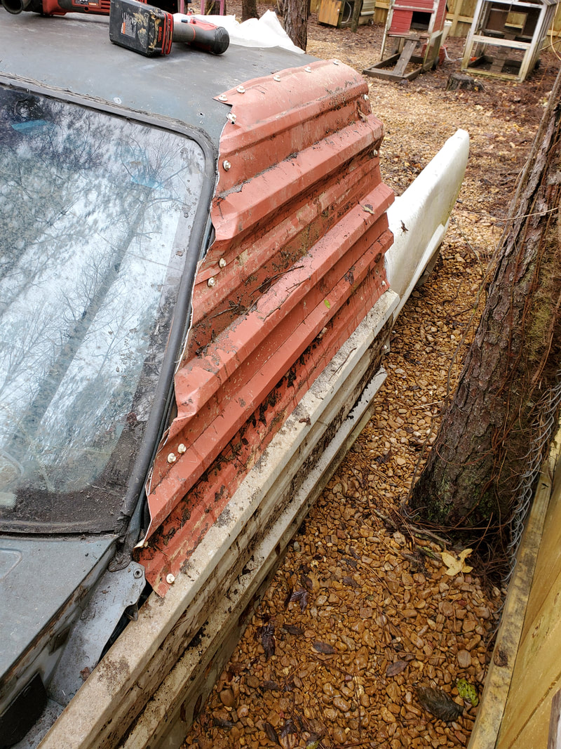
Sheet metal panels attached to driver's side door opening to serve as a covering.
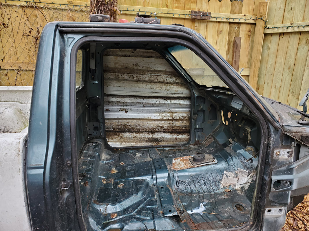
Shot of driver's side door opening through inside of cab.
With the driver's side covered up we hung the passenger side door back up. We had to remove the door prior to removing the cab as the door made for a large part of the weight of the cab. Even though we did our best trying to line up the hinges and the door, the hinges are either weak or we just didn't replace the fasteners that were compromised during the removal of the door. In the end it didn't matter since this cab is not going to be rolling down the road on a full truck anymore so even with the door not fitting flush without having to lift it up during closing, it closes enough to do the job.
Passenger door hung back on cab.
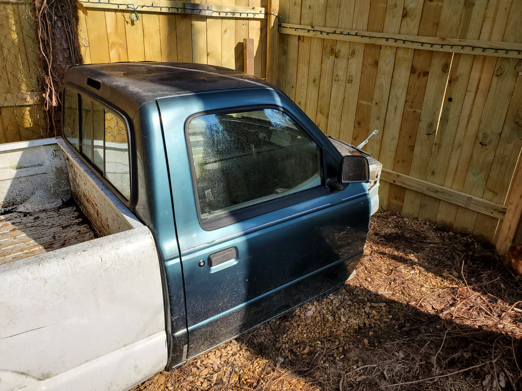
Passenger door closed on cab, note gaps in back of door.
With the cab fully enclosed the next thing I did was cut a hole in the front of the bed through to the back of the cab. This was accomplished with the die grinder cutting slits on all four corners through to the back of the cab then using the reciprocating saw to fully cut through all four sides. After doing all this cutting I had the small access opening that would allow the chickens to pass from the bed to the cab and vice versa.

Access portal cut through both bodies to allow passage for the birds through out the structure.
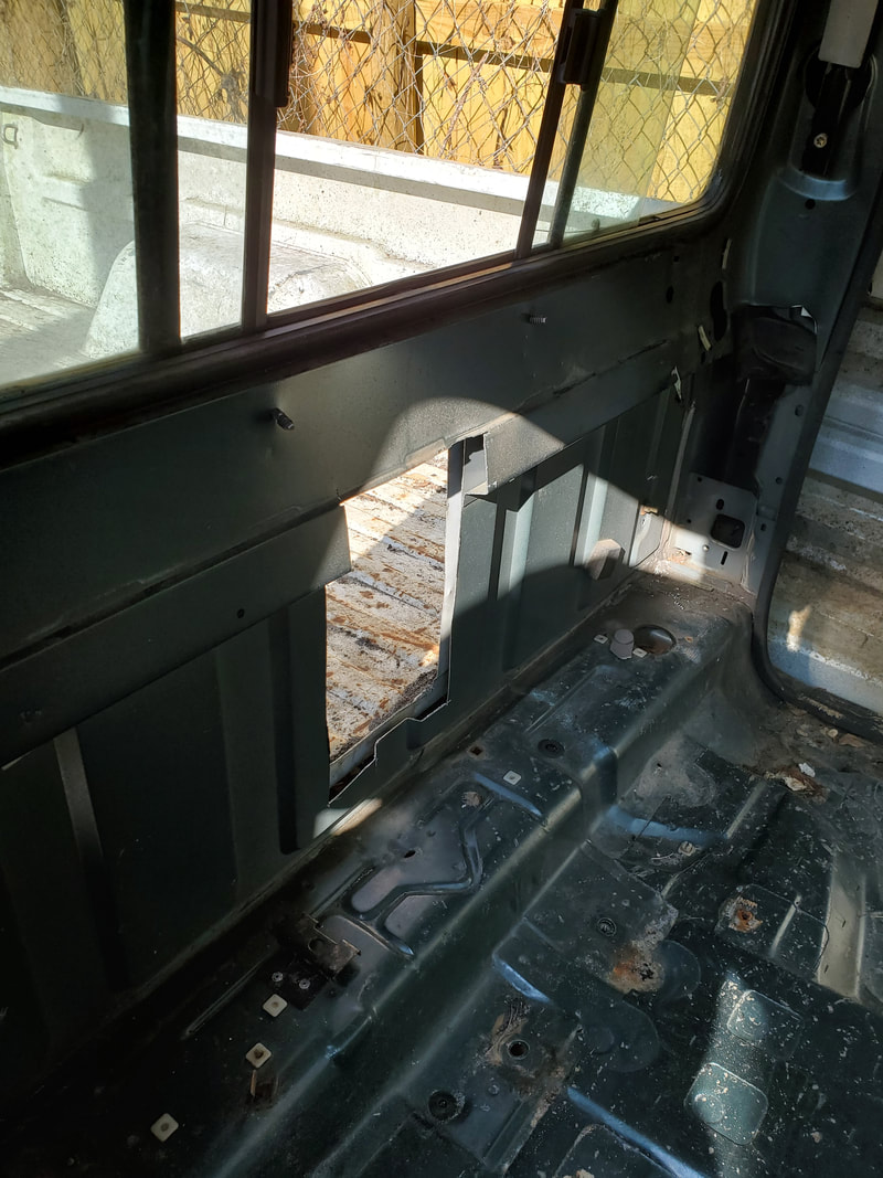
Access opening as it appears from inside the cab.
|
|
|
Now its time for hooking up the utilities in the chicken coop. I started off with the electrical system, which in this rendition will be simpler than the other two coops. Reason for this is the idea that I plan on redoing the overall electrical system of the chicken yard to where everything will be on a dusk/dawn timer that will have the lights and the coop heaters come on at night when they're actually needed. The chickens are out of the coops during the day and having lights on is just a waste of power plus with the birds out of the coops, heating them is pointless as well. So because of this, the electrical system will just consist of one junction box for outlets and the light fixture will branch off from this junction box. There will be no switch for the light either. I plan on using a four outlet square junction box as I want to have two outlets for the heater and an AC adapter for a ventilation fan (computer/power cabinet fan) and a couple of spare outlets in case I need to plug up any other devices I may plan on installing in the coop in the future.
I started off by taking a surplus junction box that has a stud mount built on to it. This was screwed into an interior subframe of the cab to hold it in place. With the box installed I put two fittings into the box, one at the top and one at the bottom. These fittings are the clamp type fittings for holding cable in place as it goes into the box. I then ran one length of cable from the top of the box up around the rear window of the cab to the center point where the 3rd brake light used to be. It was here that I mounted the light fixture. Before I could put the fixture up I had to secure the ends of the wires to the terminals. Using self tapping screws I secured the light fixture to the subframe of the cab at the point where the 3rd brake light would've gone. I used retention straps and self tapping screws to hold the cable in place as it routes around the back window and down to the junction box.
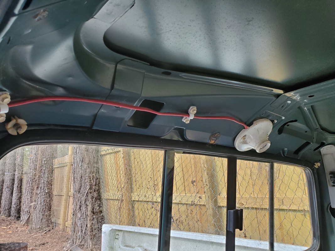
Light fixture attached to top of cab with power cable routed around back window down to junction box. Note retention straps holding cable in place.
With the light fixture cable in place I then hooked up the outlets. The outlets were linked together in parallel from the cable going to the light fixture. I then had to drill a hole in the side of the cab to route the main power cable through to feed into the junction box. After getting the main cable in place and secured through the bottom fitting in the junction box I hooked it up to the other side of the outlet pair. This pretty much completed the whole electrical system. Power comes in, goes into the junction box into one outlet, jumps over to the other outlet then continues through the last cable to the light fixture.
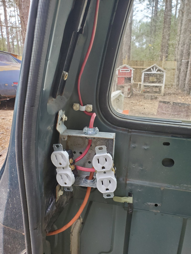
Junction box with cables in place and outlets wired up. Note main power cable at bottom running through side of cab.
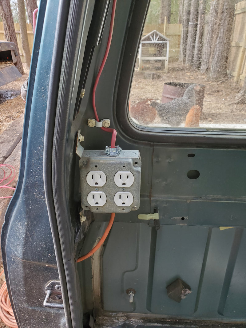
Outlets secured with box cover on junction box.
With the outlets in place there was a matter of the main power cable. As it stands the cable was sitting on top of the ground. Can't have that. I dug a shallow trench under the gravel, not into the dirt, leading to the outlet box between the Mustang Chicken Coupe and the Toyota Chicken Truck. I'll run the cable up into the bottom of the box like the main power cable that is feeding this box from outside of the chicken yard. I buried the cable in the shallow trench, covering it with the gravel that was moved to open the trench. In the future I will put more gravel down to thicken the bed to further cover things up so this cable won't be exposed.
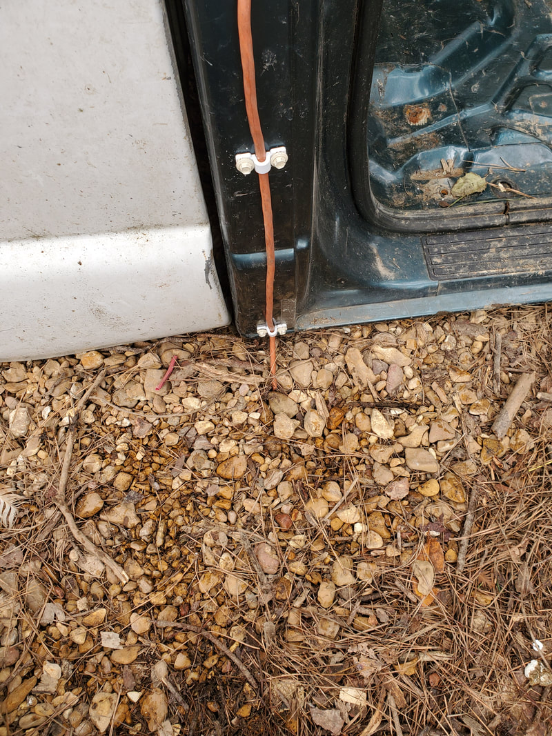
Power cable where it goes through side of cab and goes under the gravel over to outlet box.
At the outlet box I had to remove the fitting from the bottom of the box that was holding the solitary power cable. I routed the new coop's cable up into the box, running parallel to the outside power cable. I wire tied the two cables together all the way down to the trench for the new cable. I wired this cable to the single outlet in the box since outlets have two sets of terminals to allow for linking multiple outlets/loads together. With the power cable hooked up to the outlet, getting outside power I was able to power up the light and the outlets in the coop. I put an LED light in the socket and plugged up the personal 250w electric heater that I plan on using in the coop. Everything came out as intended.
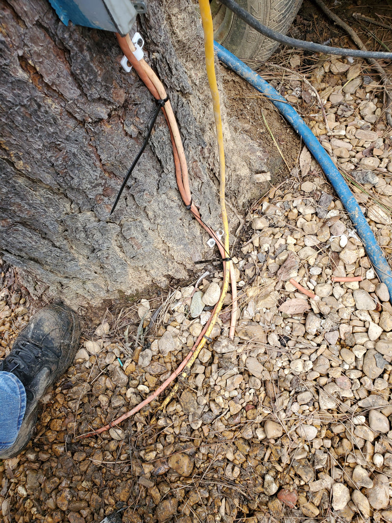
Dark orange cable going to new chicken coop coming up from trench and wire tied to other power cable going into outlet box.
LED lamp in place in socket and powered up.
Another little feature I had to do was install a shelf for the electric heater to sit on. The heater that I chose to use was a table top personal 250w heater that had to sit on a flat surface to work as it has a tip safety switch that will cut the unit off it it falls over or isn't sitting on anything. To remedy this I took a larger piece of sheet metal and folded it in half. The bottom part of the shelf angled downward to the wall. Welding the shelf to the back of the cab next to the outlet, the bottom half of the shelf met up with the back of the cab, providing the bracing necessary to hold the heater nicely. I used some wire ties wrapped around the body of the heater and through the shelf to fully secure the heater to the shelf where it can't tip or otherwise be moved. I plugged the heater to the outlet next to it so it can be ready for use soon as I apply power to the coop.
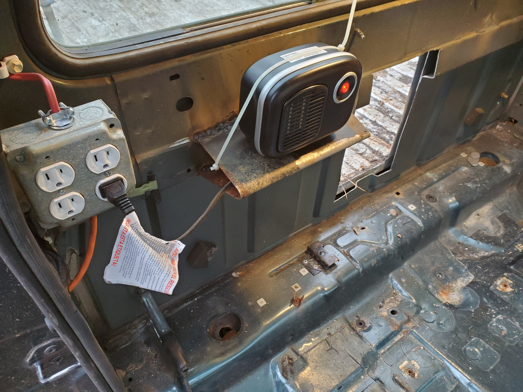
Shelf made to hold heater in place next to outlet box. Note heater already plugged in.
|
|
|
While still inside the cab I also took care of the roosting posts. Just like in the Toyota, these were made of a couple of lengths of conduit that were run longitudinally, from front to back,being welded at the back of the cab under the rear window and on the sub frame that was used to hold the dashboard. These pipes will allow the birds to roost and be close to the flow of heat coming from the heater that is underneath the posts.
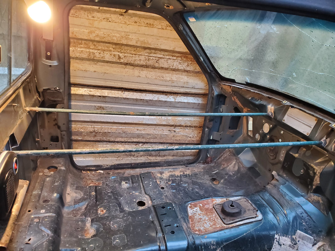
Conduit pipe roosting posts welded in place in cab. Note heater in foreground at far left.
With the electrical system done I moved on to the water. To start this off I assembled the drinker cup PVC pipe manifold, the same type of setup like what was used in the Toyota Chicken Truck. Three 1/2"x1/2"x1/8" tees and some short pieces of pipe, a cap and a smooth to thread female adapter with a hose barb nipple make up the manifold. I assembled this off the truck then secured it with conduit straps to the side of the inside of the bed at the back of the bed, same as on the Toyota.
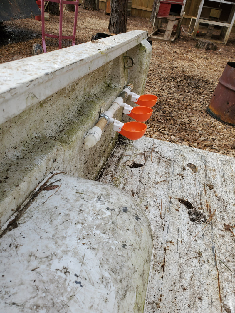
PVC pipe drinker cup manifold assembled and secured in place inside bed at rear.
The next thing was to make a platform to support the bucket. This setup and everything else, will mimic the Toyota's setup. I took a piece of sheet metal and a couple of short pieces of conduit and welded these "legs" to the corners of the piece of sheet metal. I then welded the opposite edge of the sheet metal table to the top of the fender apron then welded the bottoms of the pipes to the floor of the bed to complete the platform/table for the bucket reservoir.
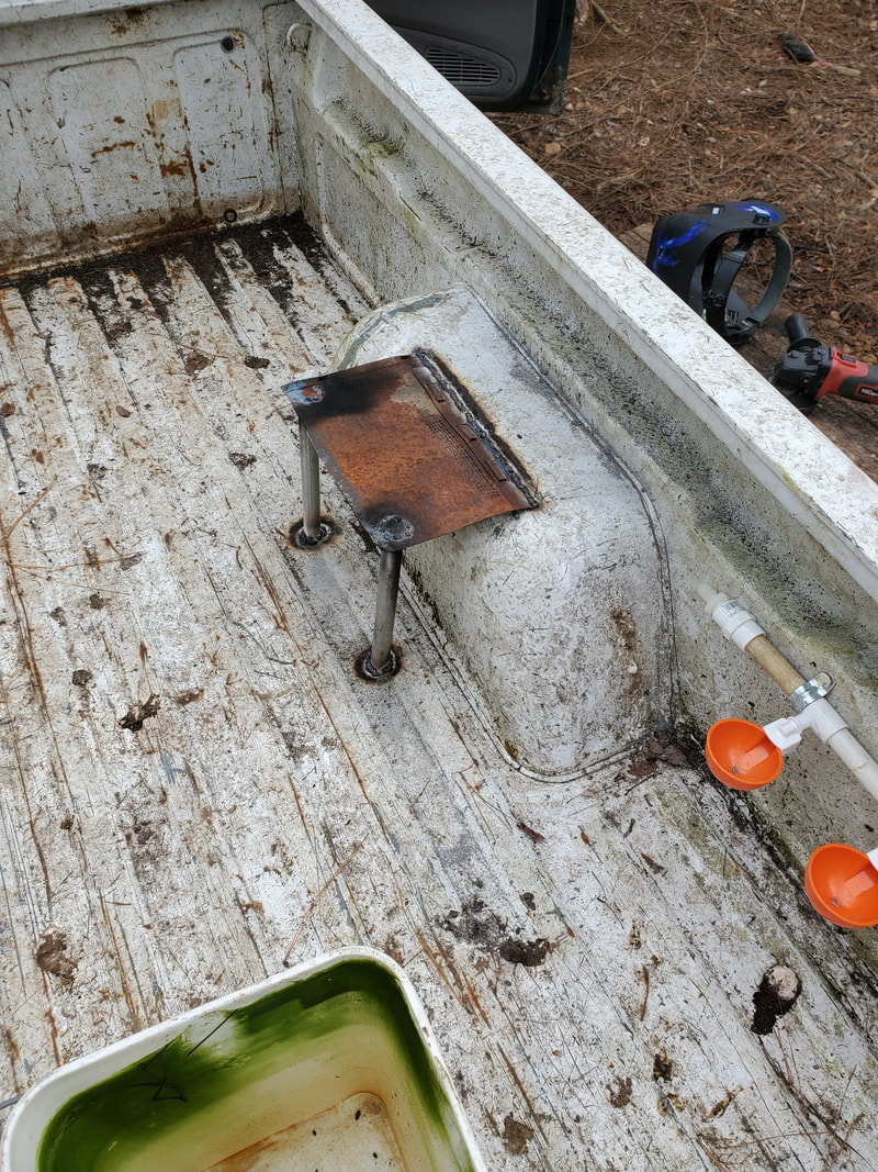
Bucket reservoir platform welded up in place against fender apron. Note close proximity to drinker cup manifold.
Now for the bucket reservoir. Just like on the Toyota, I utilized another float valve and a series of fittings to make the assembly. The float valve was secured in place in a hole drilled near the top of the bucket. A 1/8" close nipple was screwed into the float valve then a 1/8" x 1/2" garden hose adapter brass fitting was screwed to the other end of the close nipple. From here a garden hose thread pressure regulator, same as that used on irrigation systems, was screwed to the adapter. Lastly another small hole was drilled at the bottom of the bucket on the side. A hose barb nipple was screwed in place. I put the bucket on the platform and installed a short length of clear hose between the two hose barbs, linking the bucket to the end of the drinker cup manifold.
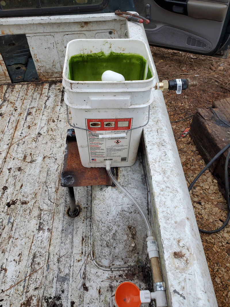
Bucket reservoir in place with hose connected to manifold and float valve assembly in place with associated fittings.
I took an old garden hose and cut a length from the hose. I made sure the length of hose would allow me to attach the hose to the bucket reservoir, route the hose along the side of the bed to the ground and along the ground in another trench over to the water line next to the Mustang Chicken Coupe. Currently there is a two way splitter but I plan on installing a three way splitter so I can attach this hose to feed water to the bucket reservoir. After temporarily hooking the hose up to the yard hose to test the assembly, the float valve came on as intended, slowly filling up the bucket and feeding down into the drinker cups. Once the cups filled they closed up and the float valve closed up after reaching the preset water level in the bucket. The regulator keeps the pressure low enough to not pop the float valve when its closed.

Bucket reservoir filled with water after turning on water supply. Note blue hose hooked up to fitting at right.
|
|
|
|
|
|
|
|
|
|
|
|
Next one the list is the bed cover. Just like the Toyota this assembly was made from conduit pipe and corrugated sheet metal. I used my pipe bender to make bends on three lengths of pipe in order to match the contours of the sides of the cab so the sheet metal will lay down smooth up to and onto the back of the cab. Unlike the Toyota I was able to get all three ribs bent up without having to cut the pipe in the middle to trim down and weld back up to make them match up to the back of the cab. I welded all three ribs, front, middle and back, to the top of the bed.
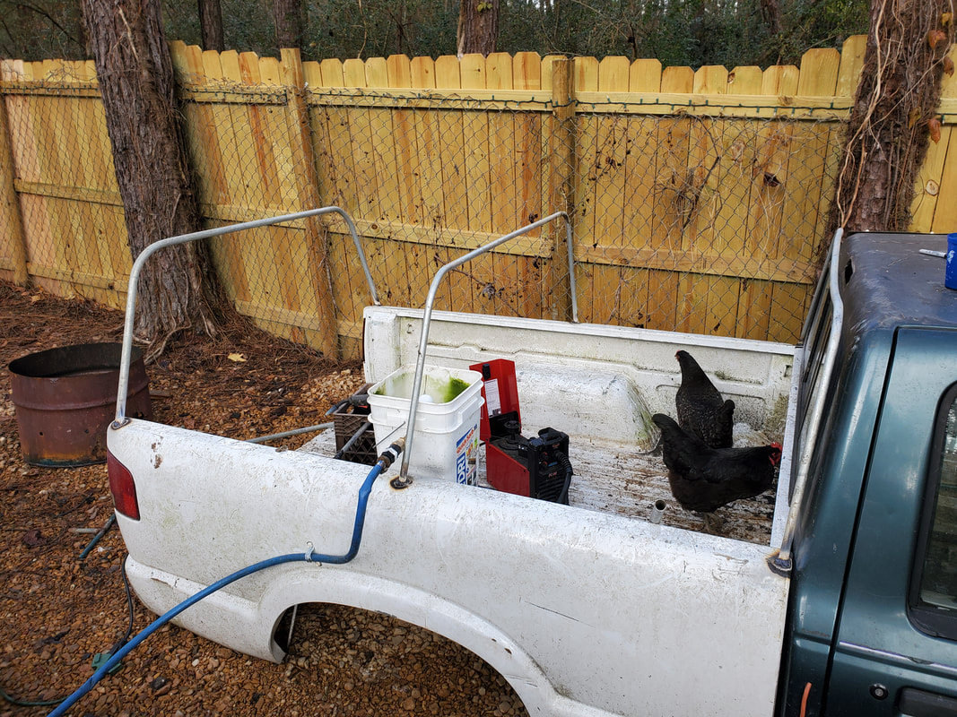
Conduit pipe ribs bent and welded in place to start the frame for the bed cover.
Next I cut and welded four pieces of pipe between the ribs, near the top to link them together to complete the overall rigidity of the structure. These pipes will also serve as anchor points for the self tapping screws when I anchor the sheet metal to the structure. With the pipes welded in place the next step is installing the sheet metal.
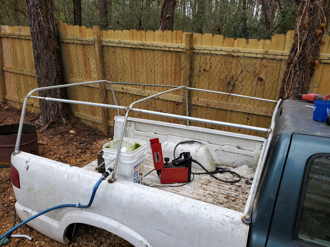
Pipes welded in place between ribs completing the bed cover framework.
Here is where things get a little hairy. Out of all my scrap corrugated sheet metal I only had two pieces of sheet metal that were long enough to actually cover the whole bed. I had some other pieces that would only cover 3/4 of the length of the bed. Because of this I saved the two full length pieces for the top, so they would shed rain water better. I attached the two 3/4 length panels from the front of the bed to the back. I cut a couple of smaller pieces to cover the final gap. Because of where the two panels met, I had to use the self tapping screws to attach the two overlapping ends together. These two joints didn't have the advantage of pipe for a solid anchor point so even though screws are "stapling" the ends together, I used some extra screws around the edges that are making contact with the pipe to further hold the panels down.
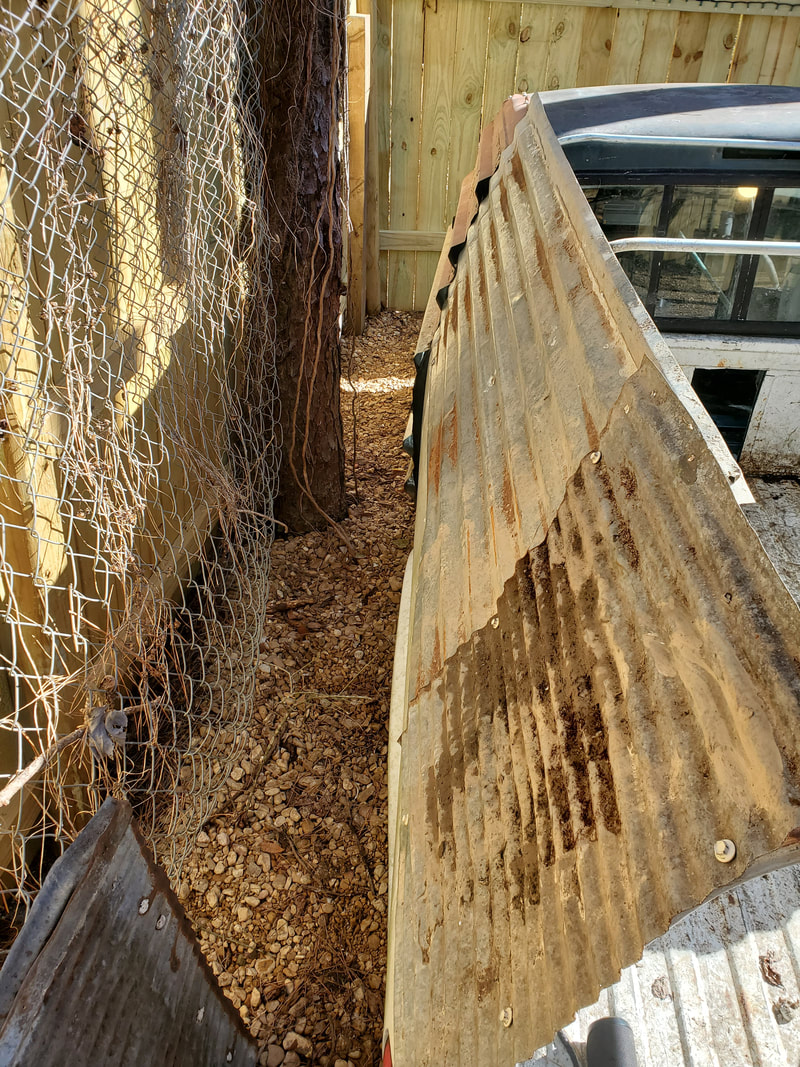
Sheet metal panels on side of bed cover frame, note short section of panel covering gap formed by first section of sheet metal. Also note screws all around the panels.
Sheet metal attached to right side of bed cover frame. Note water line from bucket reservoir protruding through cut opening in sheet metal.
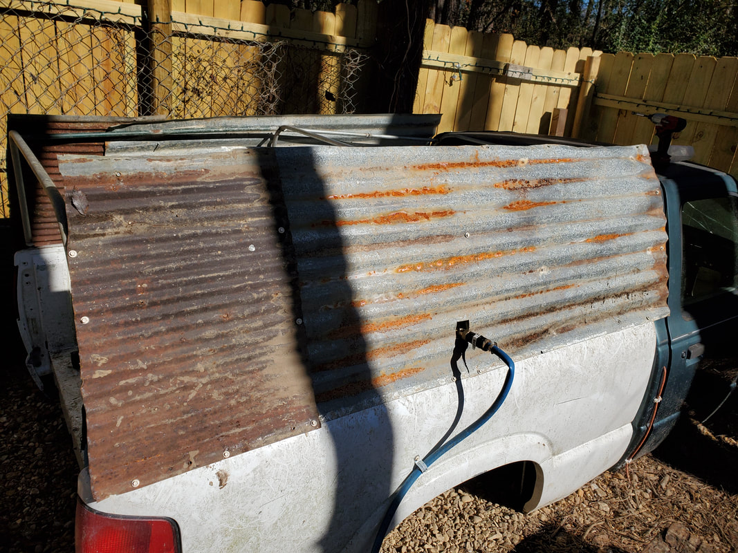
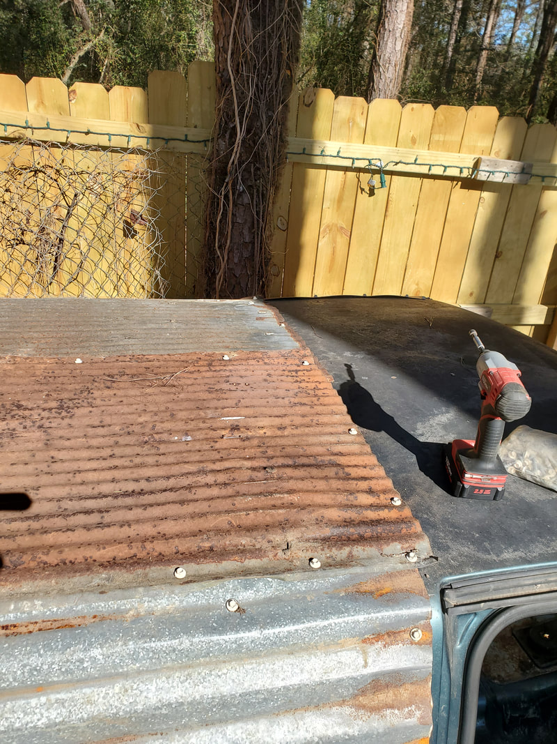
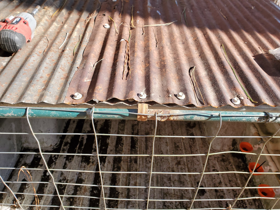
With the two sets of shorter panels installed on the sides I installed the two full length sheet metal panels on the roof. After securing the panels with more self tapping screws on the roof I cut the excess overhanging metal from the rear, cutting things flush. After doing this the bed cover was complete with the entire frame being covered by sheet metal.
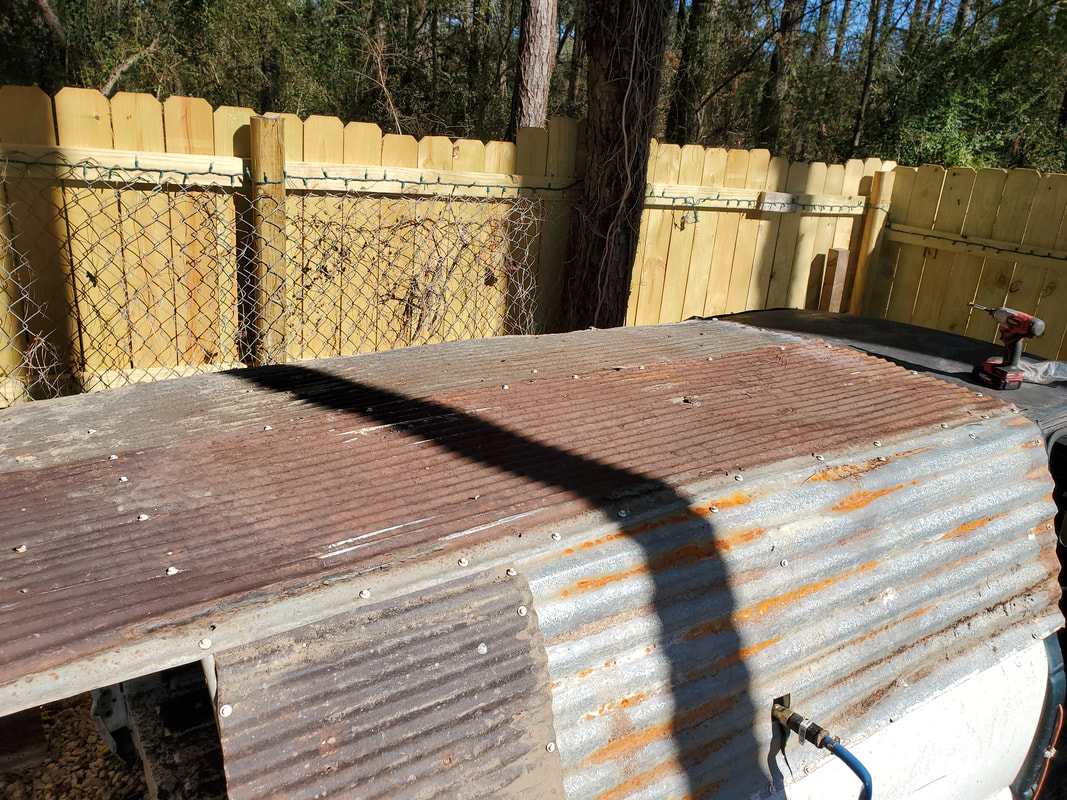
Top panels of sheet metal installed, note overhanging metal at rear.
Front of bed cover showing screws going around back of cab to make the metal be flush with the contours of the cab.
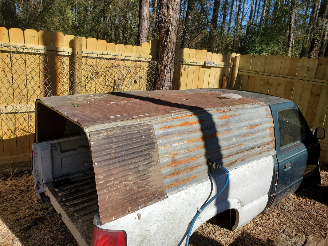
Bed cover after trimming excess sheet metal from rear.
|
|
|
|
|
|
With the bed cover done there's only a couple of things left to do on the S10 Ranger Chicken Coop. One is making a hatch to cover the rear of the bed. Since there isn't a stock tailgate on the bed and the cover is homemade, everything would have to be homemade to cover up this opening. While I could've bypassed the whole hatch idea since the coop really doesn't need to be secured with a hatch, I did think about a side benefit for the hatch.
First of all was the idea of how to set the hatch up. Since the two bodies are right on the ground, making the hatch hinge at the top would present a serious obstacle to having to enter the bed of the coop if need be. The only other solution was to hinge the hatch at the bottom. By doing this one can still enter the bed easily without having to almost crawl on their hands and knees and the biggest benefit is the idea that the hatch on the ground serves as a ramp for the birds to be able to easily enter the bed without having to jump up.
To help make the hatch I would use more conduit to weld up a hatch that comes in two parts. The bottom part that would mimic the tailgate would be welded up as a rectangle. The top part would be a trapezoid as it would angle inwards as it goes up to the top of the hatch. After welding the two sections together, I took some more corrugated sheet metal and cut two large pieces that I then attached to opposite ends of the rectangular bottom half of the hatch. This left a small center section exposed due to the short length of the panels. Just like with the sides of the bed cover I had to cut a small piece of metal to fill this gap, using screws to "staple" the overlapping ends of the sheet metal together to fully secure everything. There was plenty of conduit to use for anchoring the sheet metal to. After adding the sheet metal I cut some chicken wire and started securing the fencing to the top half of the hatch. I then trimmed the excess fencing from around the edges, folding the pieces of the fencing around the conduit to help further secure the material to the frame. Wire ties completed the attachment of the fencing to the hatch all around.
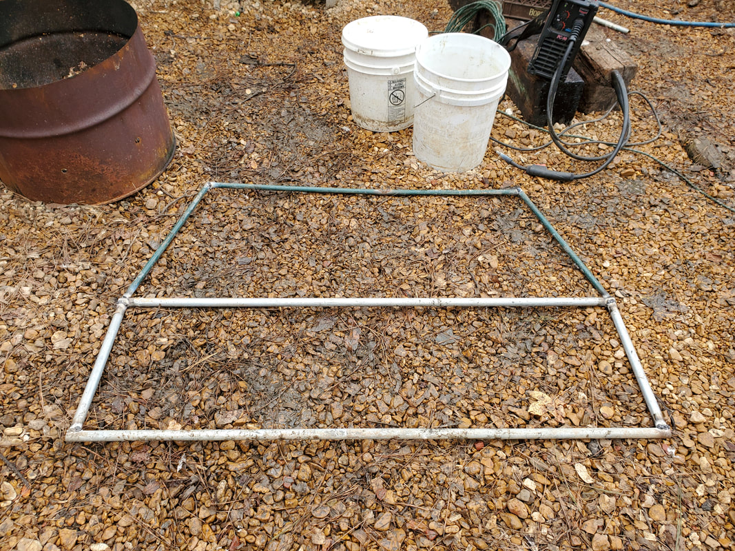
Hatch frame comprised of two different shapes made from conduit pipe.
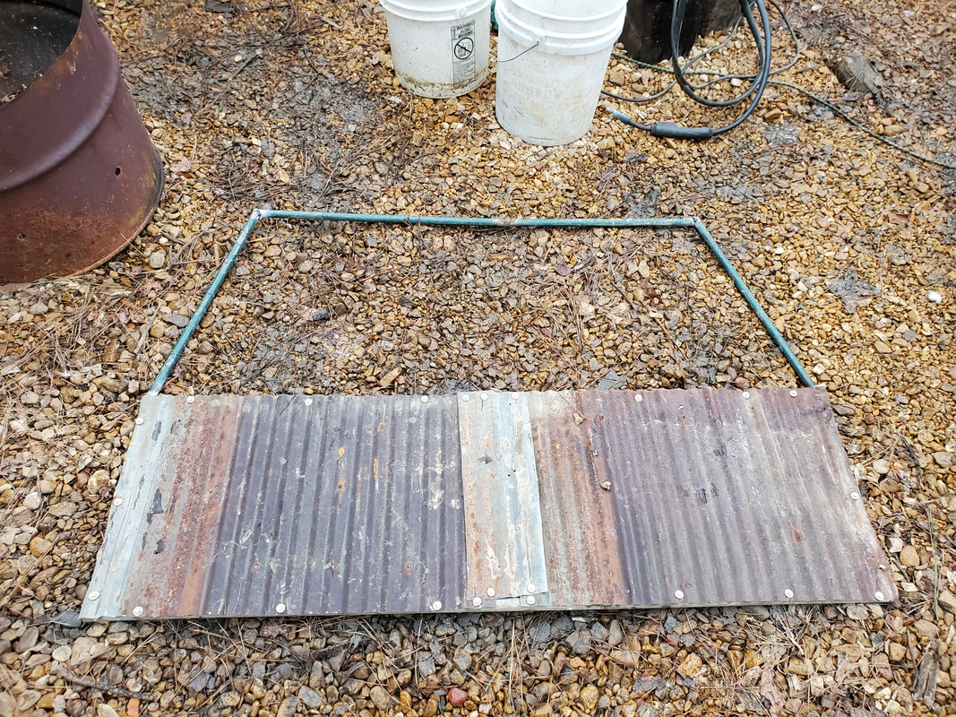
Hatch with corrugated sheet metal attached to rectangular bottom portion of hatch.
The hatch was attached to the bottom of the bed using a couple of surplus hinges I had laying around. I welded the hinges to the hatch frame then used self tapping screws to fasten the whole package to the bottom of the bed. This would allow for easy removal if need be. If I welded everything up I would've had to grind the hinges apart to remove them so I used this combination. With the hatch secured, the last thing was to fabricate a small hatch for it.
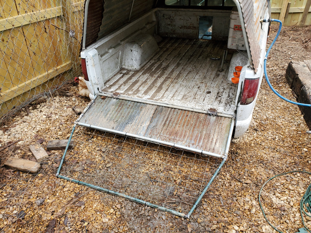
Hatch attached to bottom of bed and laying down to serve as a ramp for birds.
Hinge welded to hatch frame and secured to bed via self tapping screws.
For a latch I made things simple. I just took a conduit strap that is used for securing pipe to a wall and bent it some. I then removed one of the screws that was securing the corrugated sheet metal to the top of the bed cover frame and inserted the tabbed side of the strap under the sheet metal then reinstalled the screw. The bent loop of the strap was down enough that it allowed for me to put the hatch in its upright position and move the strap loop around the pipe of the hatch, holding it in place. The screw that was holding the strap wasn't fully torqued down so as to allow for the strap to have more movement to allow for it being looped around the hatch's pipe. With that the hatch was completed.
Conduit strap secured under sheet metal via screw, used as a latch to secure hatch in closed position.
Lastly there was a spot on the cab that I wanted to cover up that was filled by the HVAC box. This hole would be a problem in that it would allow for excess heat to escape during the cold nights. This was remedied by taking another small piece of corrugated sheet metal and using self tapping screws, quickly secure the piece of metal over the hole, covering it up with no other necessary work.
Sheet metal panel covering HVAC hole in cab.
With all this done, the chicken coop is ready and open for business. It's wired up, has water and everything is able to be used immediately by the birds. Other than throwing mulch inside the coop is ready to run right along side the Toyota Chicken Truck and the Mustang Chicken Coupe.
