THE MUSTANG CHICKEN COUPE
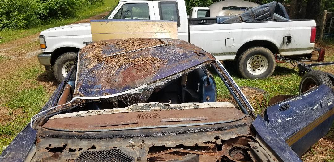
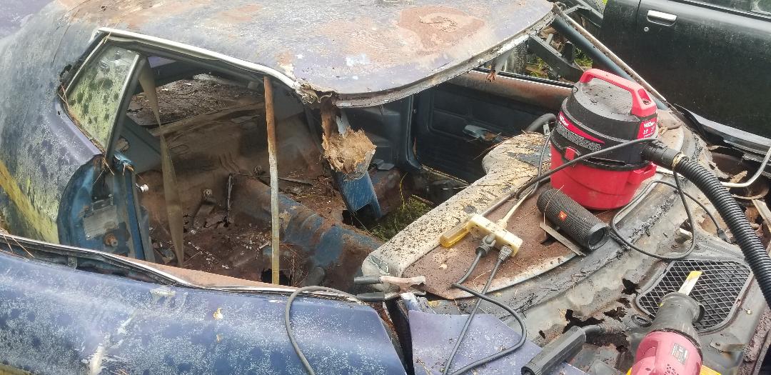
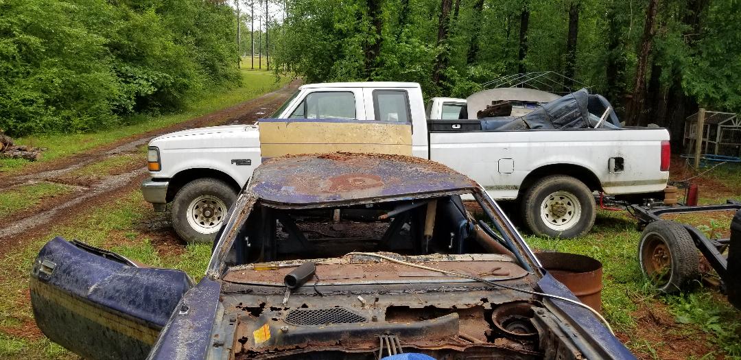
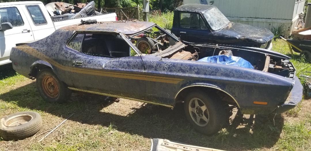
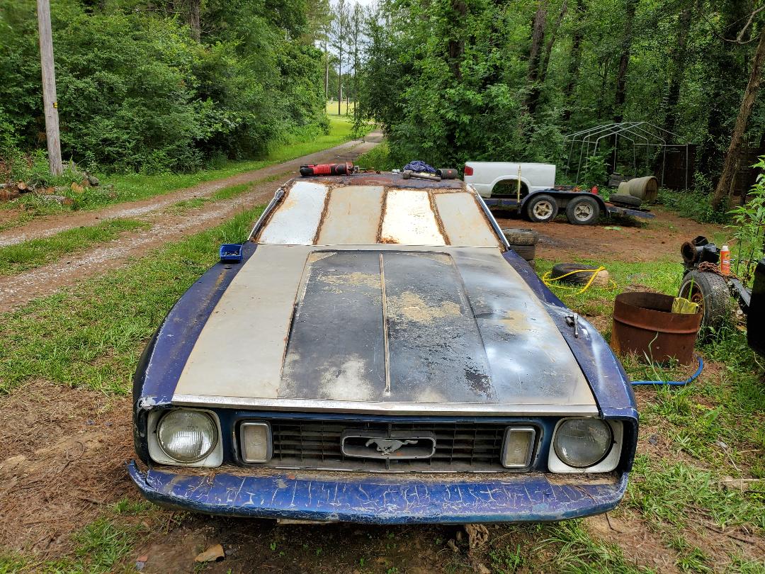
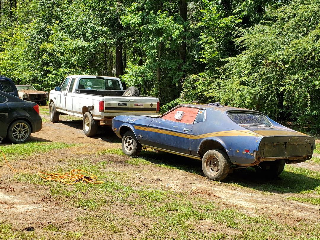
A new project in the works on the homestead is what I like to call the Mustang Chicken Coupe. Catchy and corny because the project is based on a 73 Mustang coupe. This project has its beginnings with the poor Mustang that got its roof and rear end crushed by a couple of trees in a storm that passed a while back. In the beginning the fate of this car has changed several times since when we first got it home a few years ago. In the beginning I was going to restore the car with the intent on selling it but after some analysis I determined that I couldn't sell the car for enough to make up for the money I'd have to spend to restore the car even somewhat well. I had a couple of other crazy plans like putting the rusty body onto a truck frame like the other Rustangs on our lot and had even tried to sell the car only to have people be interested in the powertrain. I eventually planned to just pull the powertrain to use it in the 69 Mustang when I put it on a truck frame and just use the otherwise useless body as the basis of a chicken coop. After seeing examples of this concept online I figured this is the best thing I could do with the body since the only other fate for the body is a date with the crusher. After the trees fell on the car this definitely set in stone the use of this car as a chicken coop, since there would be no way to repair the damage enough to even try to restore the car enough for even personal use.
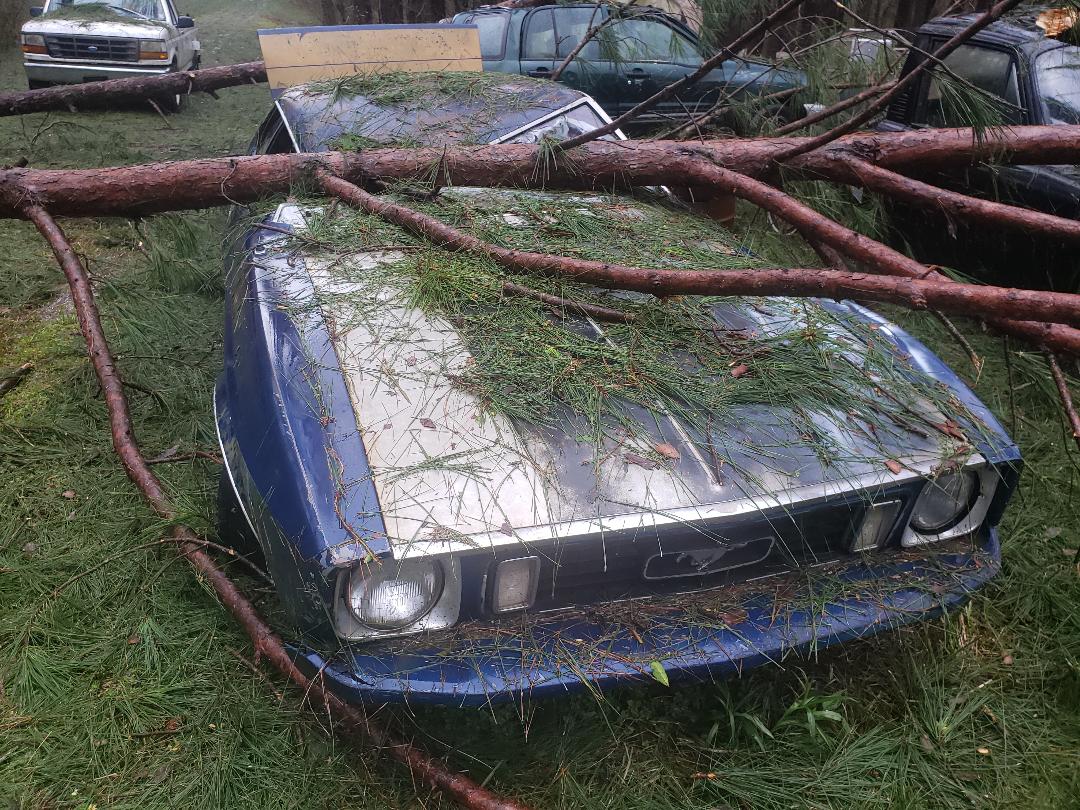
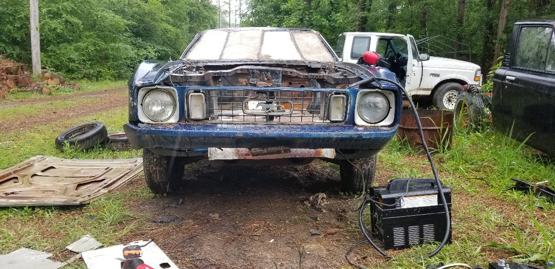
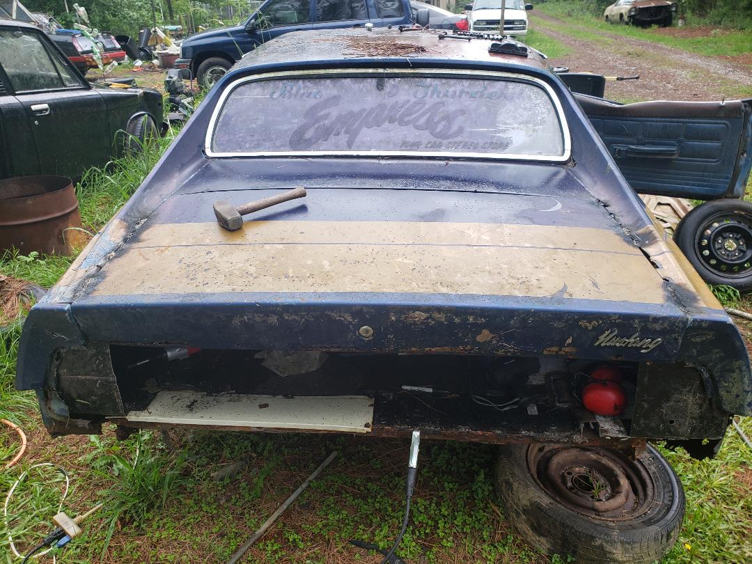
Mustang after trees fell on body.
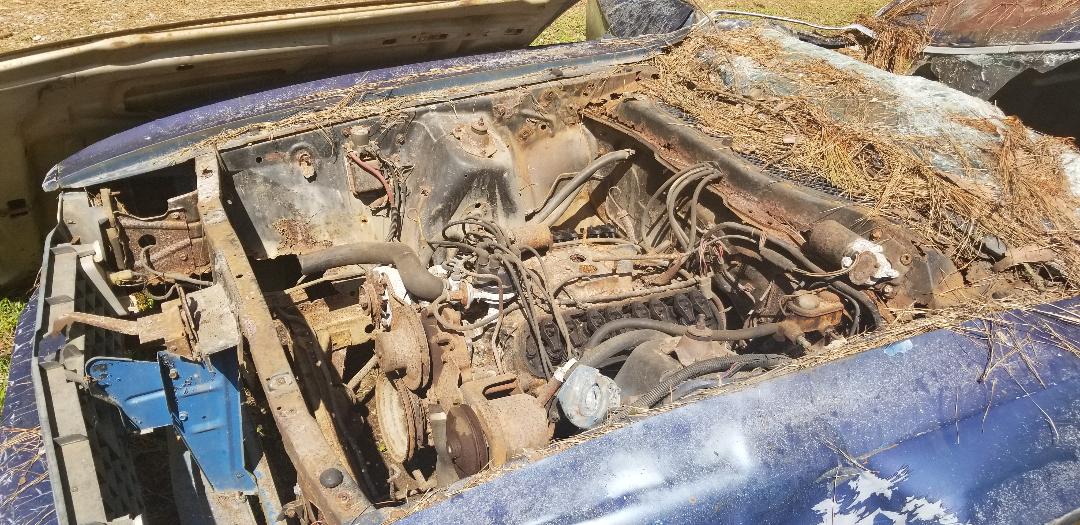
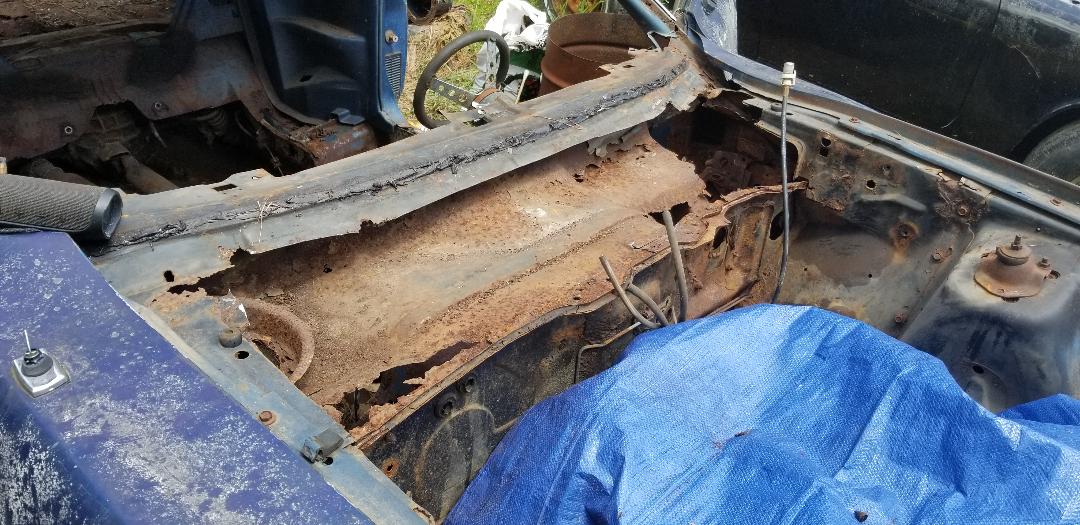
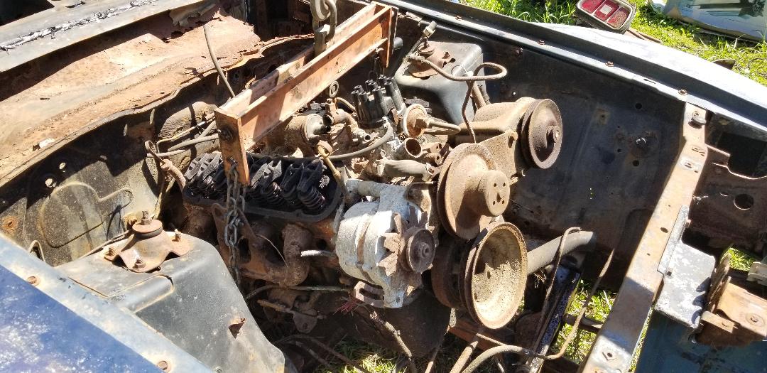
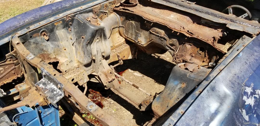
Mustang engine bay pre-stripping.
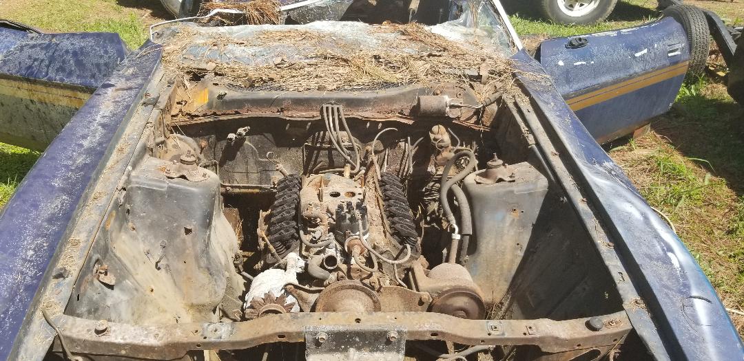
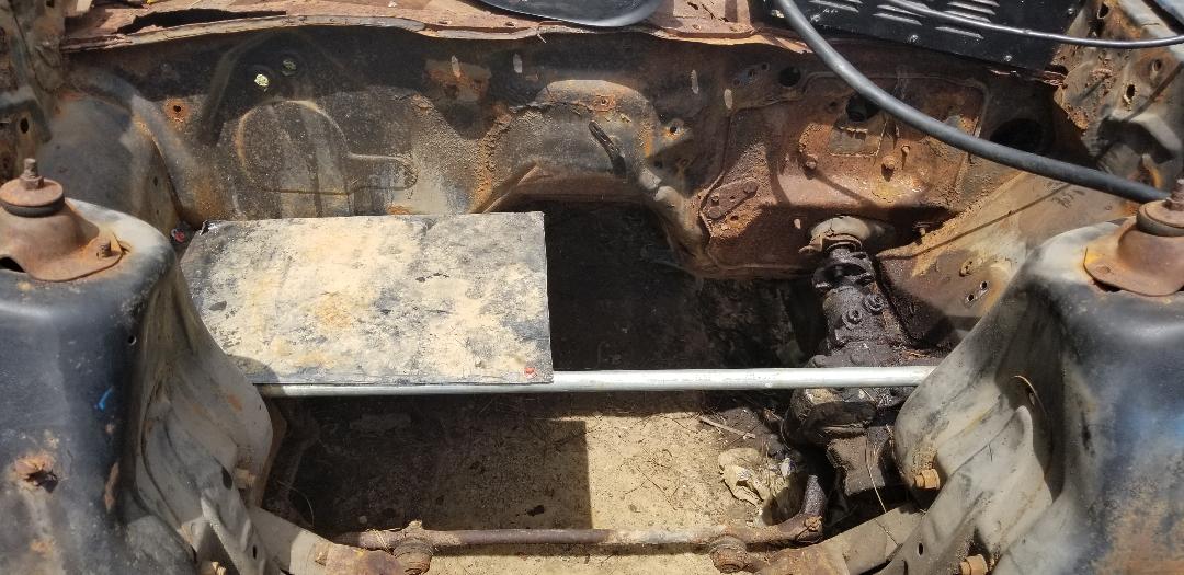
Engine bay in the process of cleaning up.
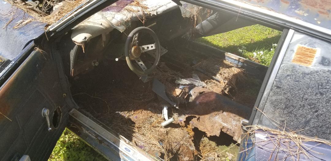
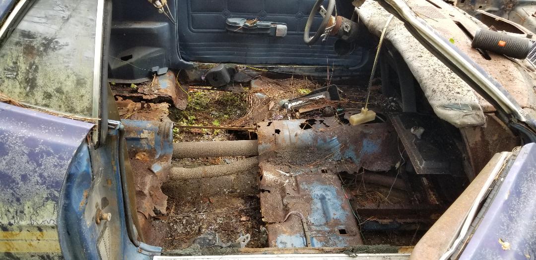
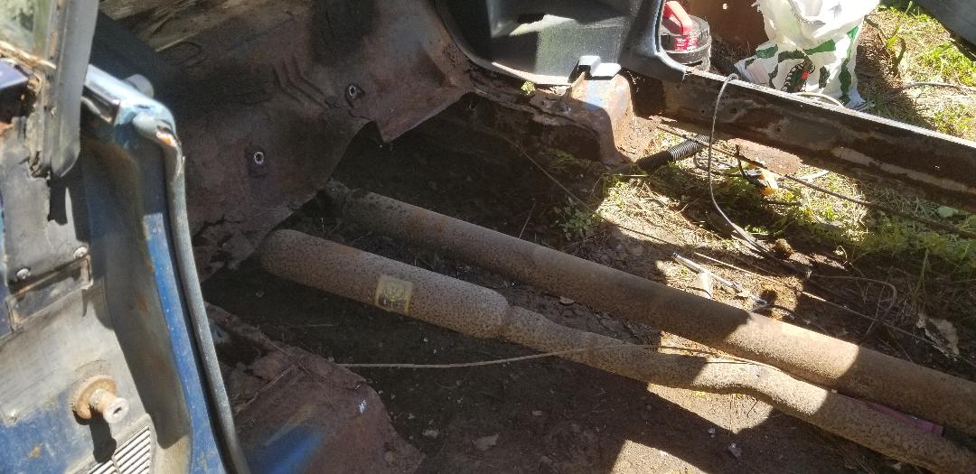
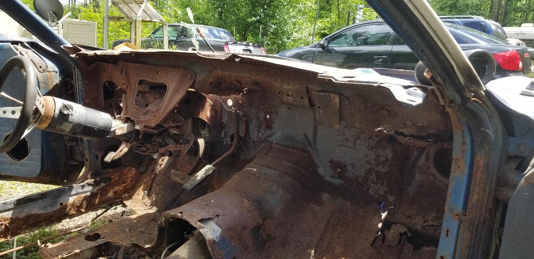
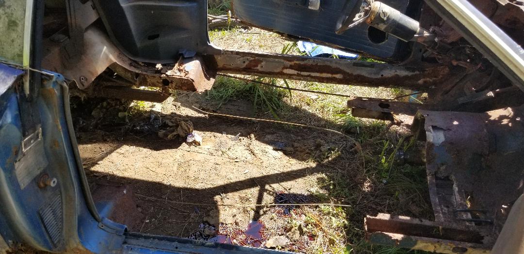
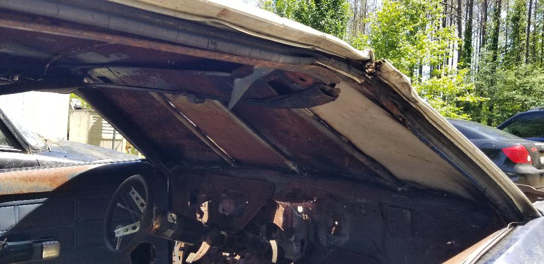
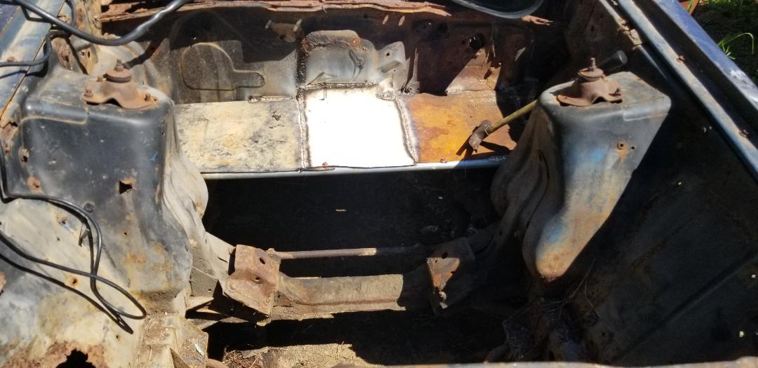
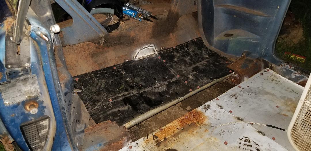
Interior prior to cleaning up.
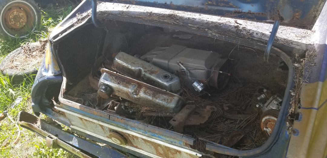
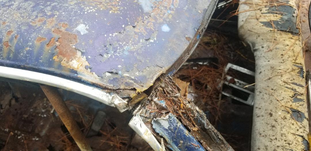
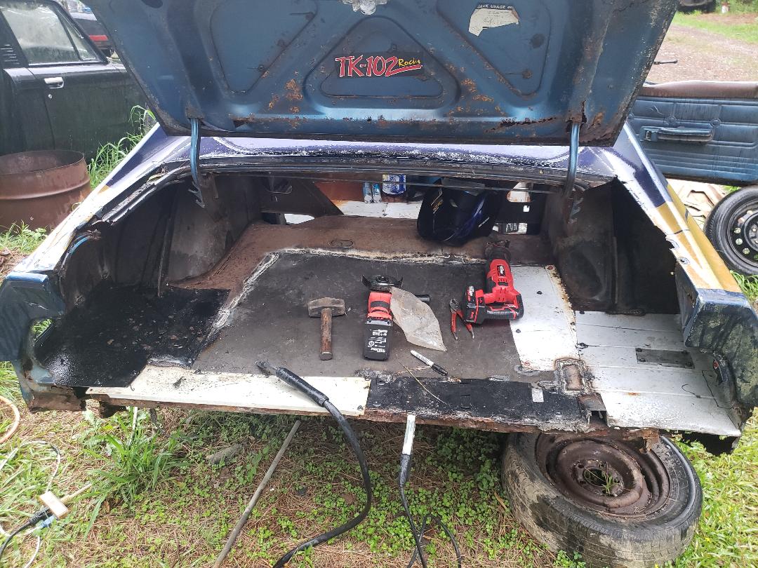
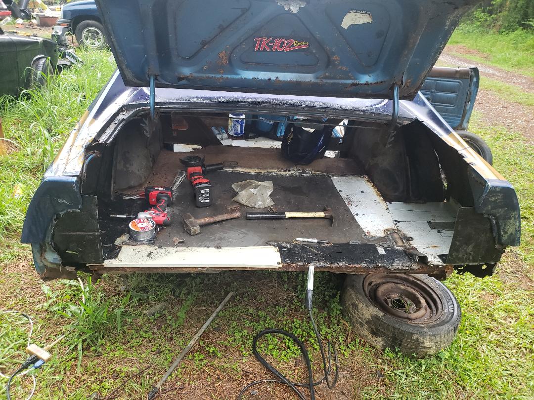
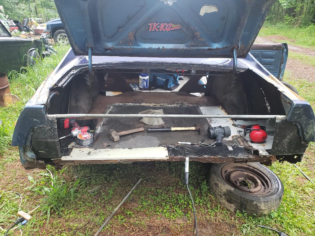
Trunk full of shit, note right rear corner of quarter where its damaged.
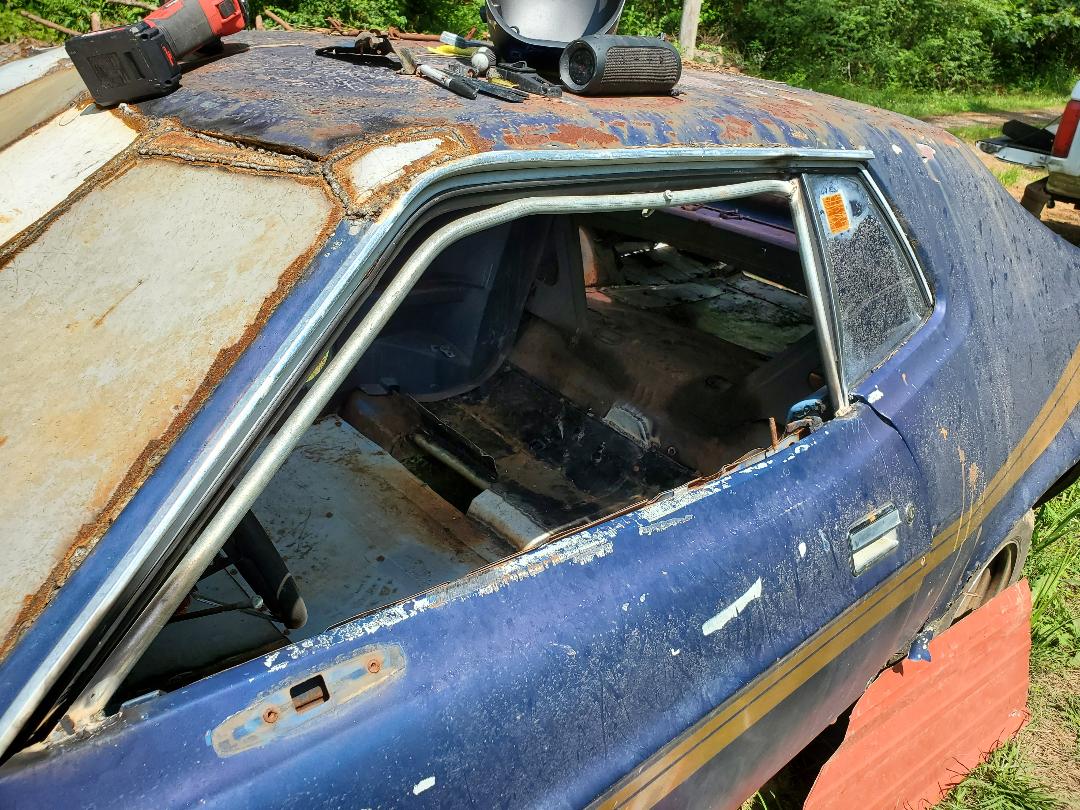
I have to strip the car down before I can start the work with converting it into a chicken coop. This will involve pulling the powertrain, any extra components bolted to the insides, the dash, gauges, wiring, basically everything in the car will have to go. I started off with pulling the hood and started cutting hoses and tubes around the engine to get those things out. The wiper motor, brake master cylinder, voltage regulator and a couple of other small components came out. A bunch of junk parts I had in the trunk to convert the car to a full AC car along with some engine parts all came out as well. With that I then turned my attention to the next thing, removing the broken glass that used to be the windshield.
The windshield has a thin layer of clear plastic that keeps shards of glass from fragging your face in an accident. This plastic held a lot of the glass pieces, working as a bit of a double edged sword since it allowed me to pick up large pieces of plastic with the glass on it but at the same time kept me from just vacuuming the shards up in one shot. Picking up the plastic had to be done carefully so as to not get cut by any glass. Another thing that hindered me was the tar glue used in the windshield frame to hold the glass in place. This held a lot of pieces along with the plastic and as a result had to be scraped out in chunks with the plastic and glass. With a little time I managed to get all of this shit from the windshield frame and from the top of the dash.
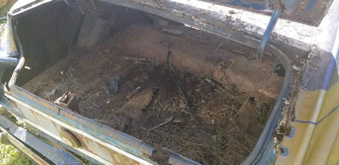
Trunk cleaned out of parts.
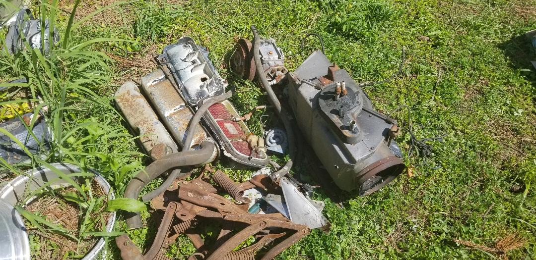
Batch of parts pulled from trunk and other areas of Mustang and set aside for sorting out for possible resale.
Windshield frame and surrounding area after removing broken glass and plastic. Pic was taken just before removing the final bit of glass from the top side of the window frame.
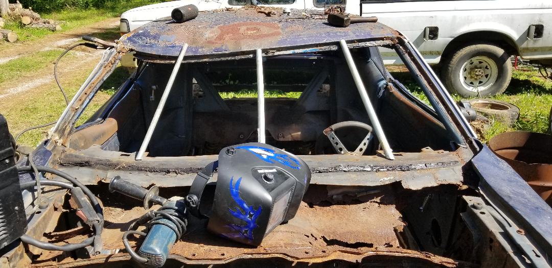
With the windshield frame cleared I then moved on straightening the crushed roof. Out came the sledgehammer. This proved to be futile as the A pillar is pretty tough, being a structural support section of the Mustang unibody. I ended up cutting the A pillar piece from the body, then straightened the bend out in that piece. Next I pounded the roof from underneath with the sledgehammer to get it somewhat straightened out then wedged it in place with a piece of pipe so I can weld the straightened out A pillar piece back in place. The welds were relatively shitty but didn't need to be super clean or tough as the A pillar piece was really just needed to hold the roof straight. The windshield opening will be filled in with sheet metal to help dry in the cab of the car in the process of making it a chicken coop, which will add to the support of the roof.
Roof showing cut out section of A pillar metal.
Cut out A pillar piece.
Mating of A pillar to roof corner.
Bottom section of A pillar mated to bottom corner of windshield frame.
Mustang roof with straightened out A pillar welded back in place. Note dent still in middle of top section of window frame.
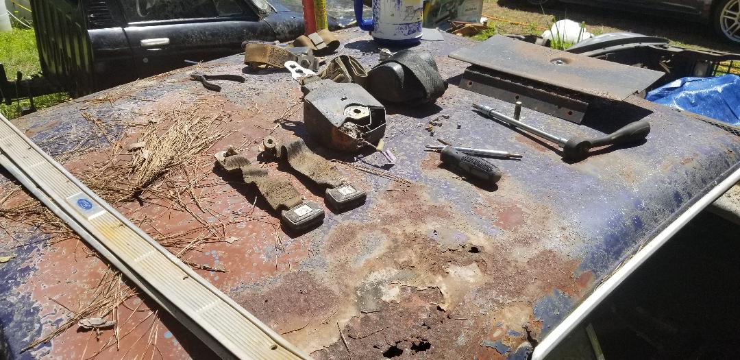
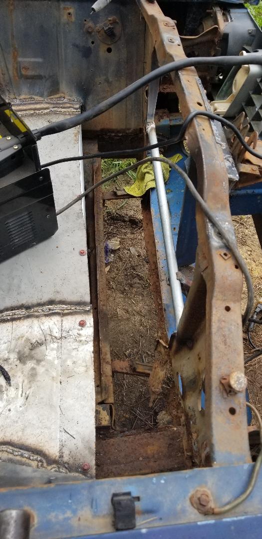
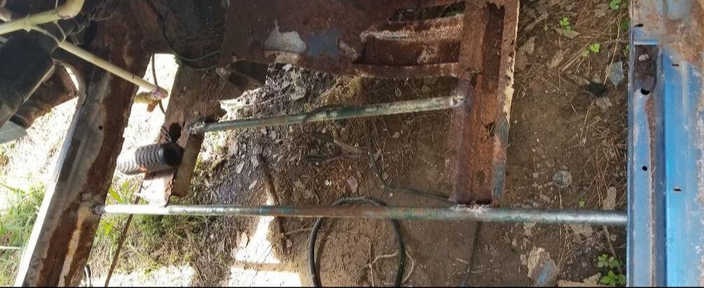
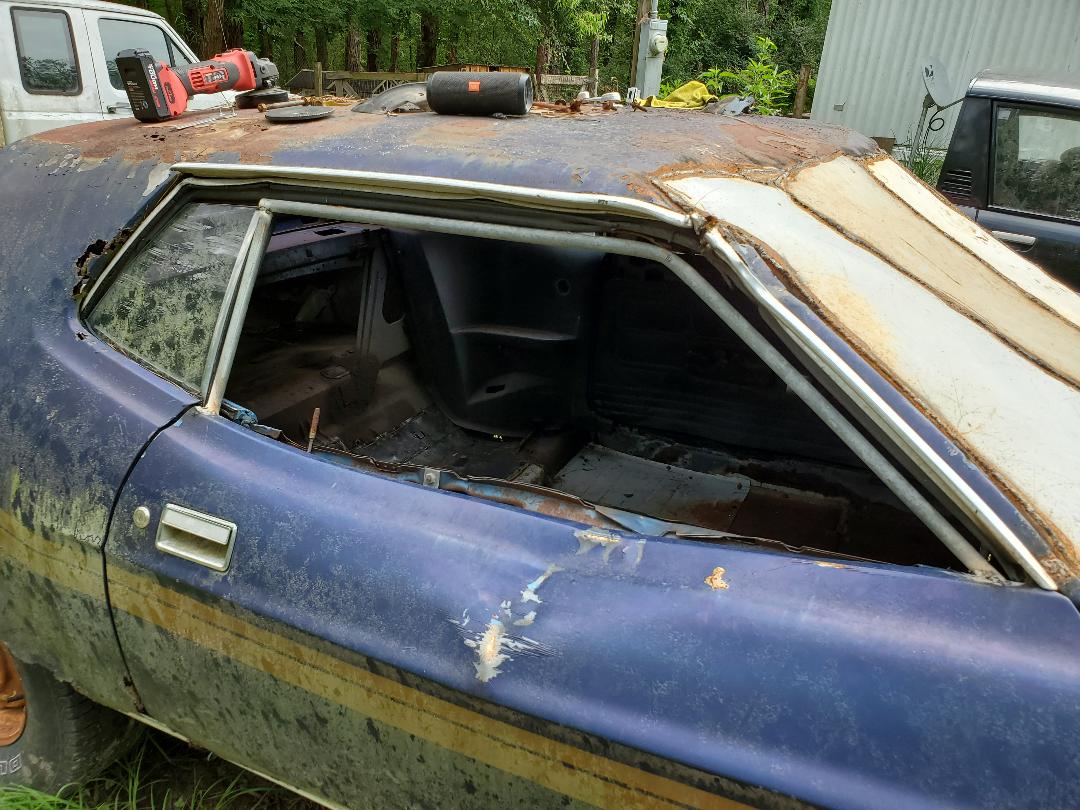
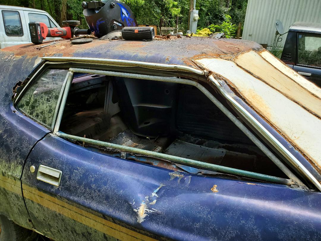
With the roof straightened out I turned my attention to the cab. The first thing I did was vacuum up as much of the broken glass as I could that was on what remained of the floors and on the ground underneath. Since this glass would have to be removed at some point after I move the car into the chicken yard I figured I might as well get a head start by vacuuming up some now. There was more of that plastic I mentioned earlier but aside from that, cleanup went pretty easy. It was more time consuming since there was picking large pieces of glass from the nozzle of the vacuum and throwing them into a garbage bag as well as emptying the vacuum can every now and then when it filled up too much. With the glass removed from the interior floors the next thing was to start cutting rusty floor pans out.
I started with the section of floor between the front of the back seat and the rear of where the front seats would've been. This would've been the same area the back seat passengers would've put their feet. I cut this section the whole width of the car and between those previously mentioned points where feet would go, including the driveshaft hump. From there I moved on to the back seat area, again, cutting the whole section from left to right and all the way back and up past the rear seat belt buckles. Of course the belt buckles had to come out first, especially since this is something that might be worth something to someone trying to put a Mustang back together. Same goes for all the other seatbelts and buckles.
From there I moved on to the front sections of floor. This time I had to cut around the subframes and up to the transmission crossmember more towards the front of the cab, but still including the driveshaft hump. I also had to cut the opening for the shifter since the aftermarket shifter that was in place had a cable running through the opening. After pretty much killing my Harbor Freight saw with all the cutting, I finally managed to cut out the rusty sheet metal that I intended to remove from the cab of the car.
Batch of interior parts removed for salvage and possible resale.
Section of floor cut from Mustang interior.
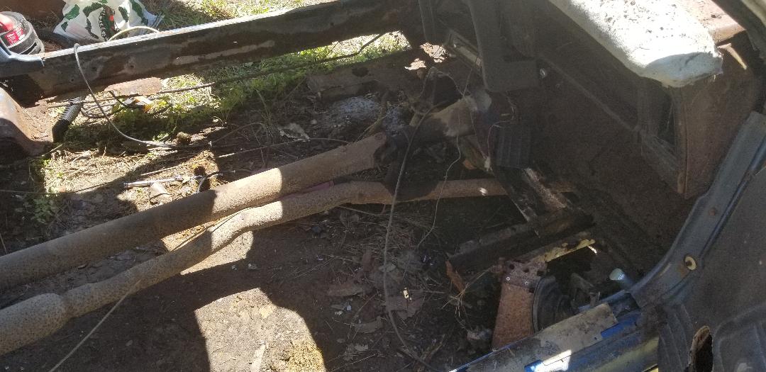
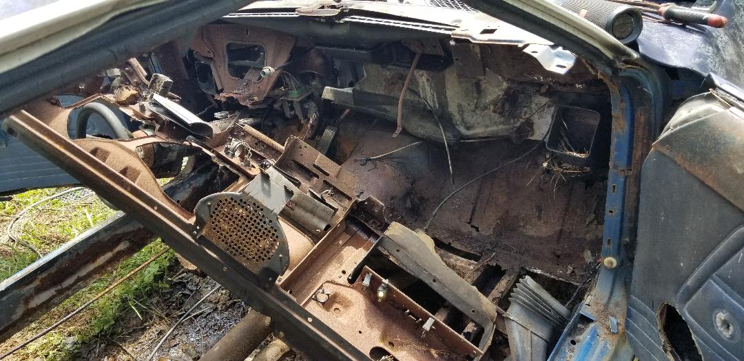
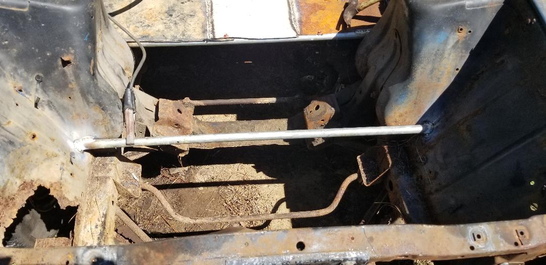
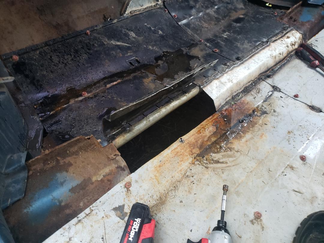
Front half of interior with floor removed, note subframe rails and crossmember towards right side of pic.
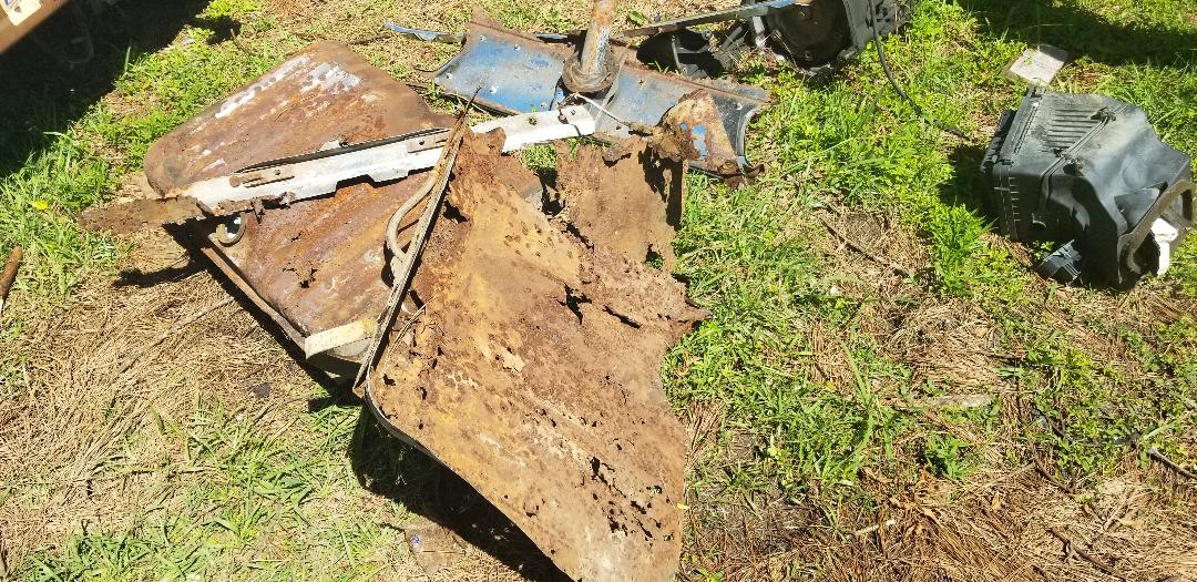
Rear section of floor pan cut out.
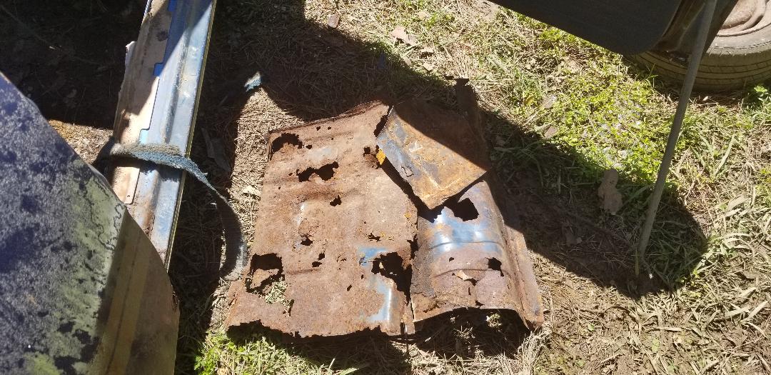
Sections of floor pan cut out from interior.
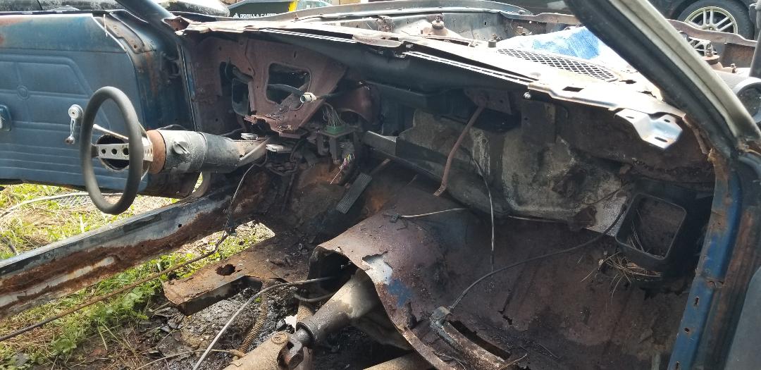
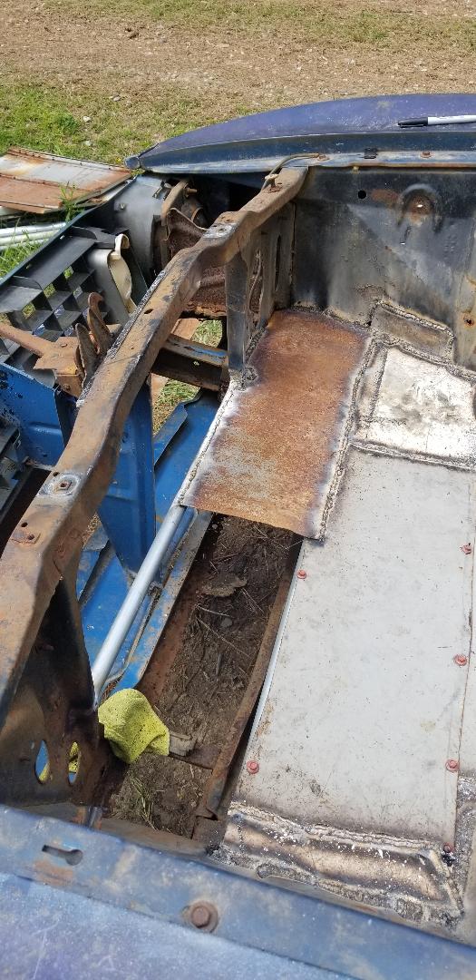
The next move is to pull the whole dash/frame/HVAC assembly from the front of the cab. This proved rather easy. First there was the actual dash panel, which only had a few small screws holding it in place since it had tabs where it latched in place just under the windshield. A couple of screws holding a panel above the defroster duct allowed me to remove that stuff then it was just eight bolts holding the dash frame. With the frame out I was able to access the HVAC box. This also was rather easy as it was just a few nuts holding the studs behind the firewall. One of the studs broke from the box. After pulling the box from the back of the firewall the assembly separated, which sealed this thing's fate with the junkyard. With all of that shit removed from the front of the cab I secured the steering column back to its mount and cut out the fuse box mount and removed the remaining wiring from the car. The throttle cable came out and I pulled the speedometer cable through the front of the firewall. The two outside air vent boxes that mount on either side of the cab under the dash also came out, but their mounts were so rusty that even without removing the small screws that were still there holding them in place I could've probably pulled them completely free.
The last thing in this installment was cutting out a panel just in front of the windshield frame that held the wiper linkages. Some of this was rusted out to begin with and I had already cut a portion of it out in the process of removing the wiper motor. I went ahead and sawed out the remainder of this panel, cleaning up this area above the firewall that much more. With all this extra metal and hardware removed it was time to move on to the trunk.
Removing dash frame from front of cab.
Dash frame removed from area, note HVAC box still in place.
Stripped front of cab, sans HVAC box and dash frame.
Wiper panel cut free from body.
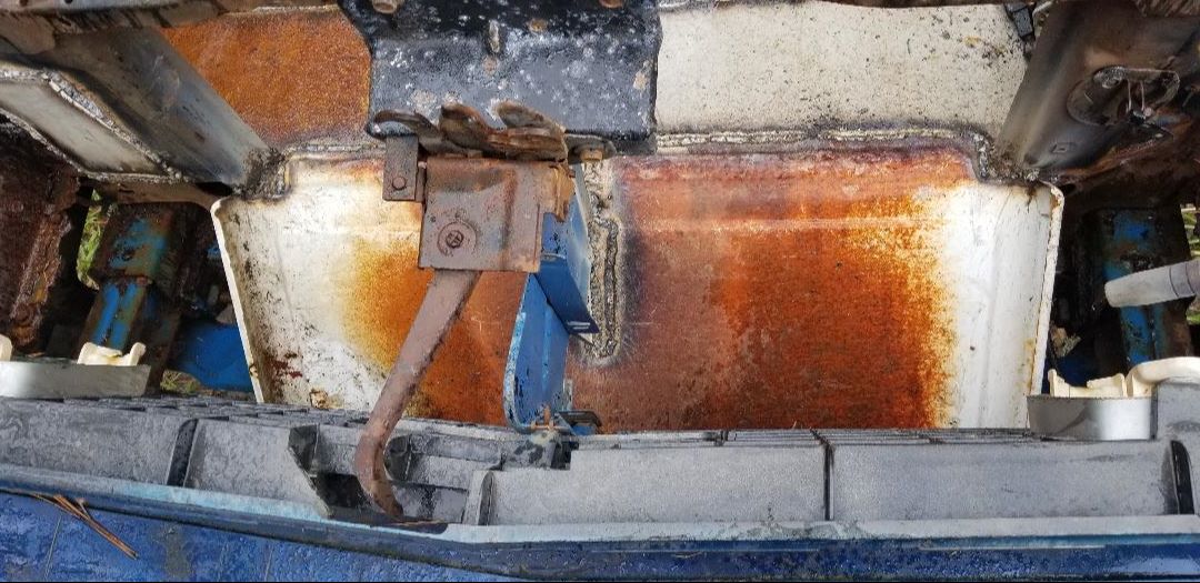
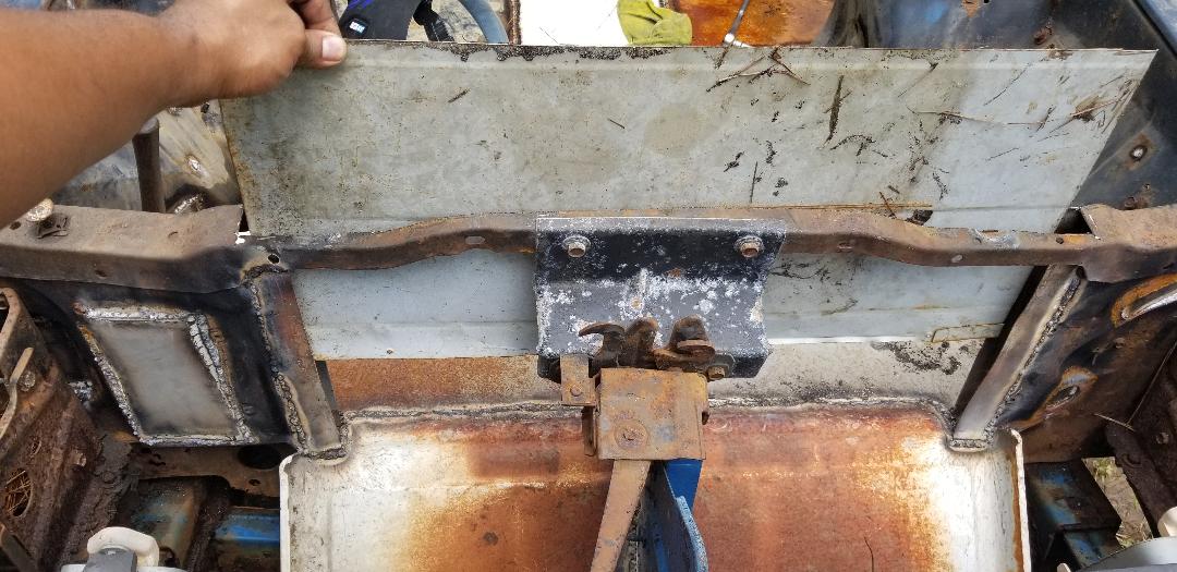
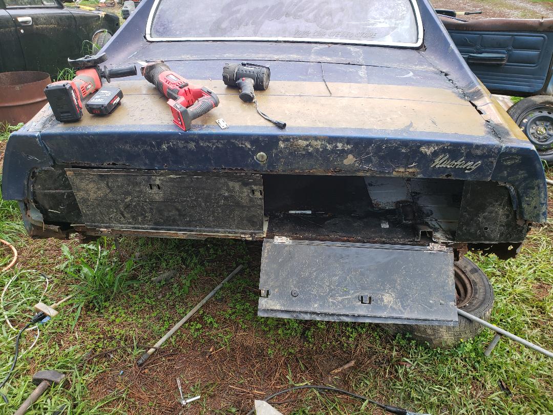
The trunk area was going to involve a bunch of cutting out of metal that was not needed in the building of what will serve as the nesting box area of the chicken coupe. I did still have to straighten out the left quarter panel though. Unlike the A pillar, the thin sheet metal of the rear quarter gave nicely allowing me to straighten it out with the sledge hammer, enough so that it lined back up with the trunk lid. I put the reciprocating saw to the taillight panel, removing it rather fast. The next area to get cut was the rusty floor just over the fuel tank. Of course my hope was that in cutting out the trunk floor I would be able to free the fuel tank just as well, killing two birds with one stone. A little more trimming in the brace that held the taillight panel cleaned up that area some more. I left enough area past the rear subframes for me to be able to weld some sheet metal to later in the construction of the nesting box area.
I also installed a large 15" rimmed tire I had in my junk pile that had the same bolt pattern as the Mustang's. Lastly I took the 69 Mustang's spare tire and put that on the other side, giving the Mustang body four good wheels so I can be able to roll the body in the removal of the powertrain. That will be the next move, getting things set up for the removal of the powertrain. This will involve disconnecting the engine and tranny mounts, removing the driveshaft and getting the crane set up and hooked up. Once that's done, then the second half of the project begins, actually turning the car into a chicken coop and brooder box.
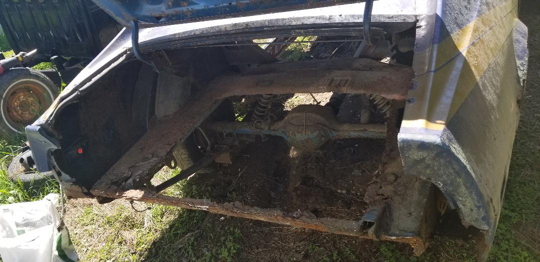
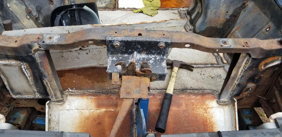
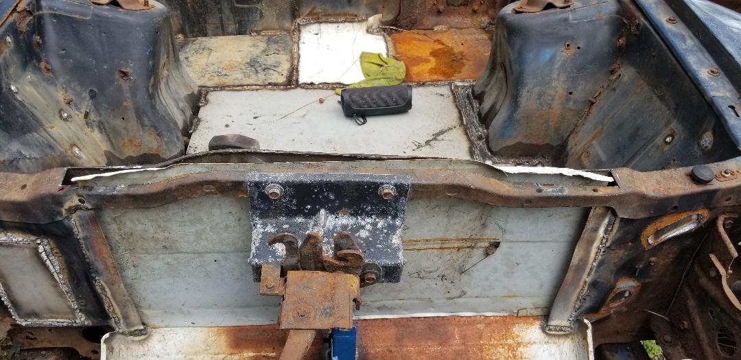
Cut out trunk area leaving subframes and some support metal. Note left quarter straightened out but with a dent still in place.
Scrap metal from trunk floor and taillight panel staged for disposal.
Car on four good wheels.
The next order of business was to remove the powertrain. The first thing that had to be done was moving the car forward before staging the engine crane in front of the car. This way we would have plenty of room behind the car to move the body backwards as the engine and transmission are pulled free. This was accomplished with our little Chevy Tracker and a tow strap. After getting the car staged, the next thing was staging the engine crane. Since the engine already had lifting loops bolted to the exhaust manifolds, I was able to bolt the chains right to these points. I then turned my attention to the interior to disconnect the driveshaft, transmission crossmember, exhaust and shifter.
Since the floor was already cut out, the removal of all of these components went pretty fast. Four nuts had the driveshaft out. Two bolts had the crossmember out and because the mount was bad, it was also free from the transmission too. The shifter cable was secured via two bolts to the side of the transmission so that unit came out rather fast. As for the exhaust system I chose to cut the pipe just in front of the merge/Y pipe section. This way when I pull the exhaust manifolds, there would be enough pipe coming from them to give me something to extend as part of a true dual exhaust system in another car. As for the rest of the exhaust system, it was just the Y pipe, a short length of pipe going to a cherry bomb muffler and a short piece that terminated just in front of the rear end. I kept the rest of the exhaust intact despite there being a break in the pipe midways through. This section of the exhaust system could be used for another straight 6 powertrain like in the 69 Mustang after doing a light weld up, of course after removing the Y pipe. With all of the previously mentioned hardware removed, it was on to the engine compartment.
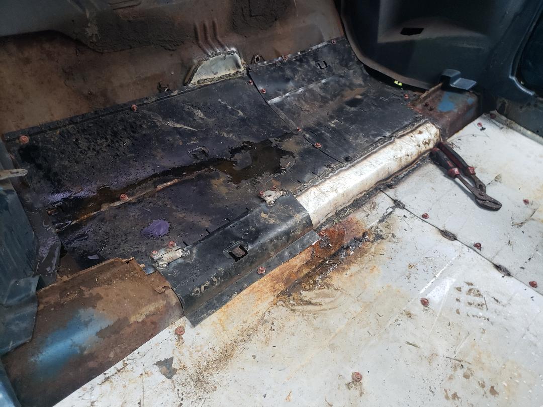
Interior after removing driveshaft, exhaust, shifter and transmission crossmember.
In the engine bay I used the impact wrench to remove the two bolts holding the two engine mounts in place. With that, nothing stood in the way of hoisting the powertrain free of the engine bay. We went ahead and jacked the engine and tranny up while at the same time pushing the car body back. Since the car already sat on a slight grade, the car rolled back rather easy. So easy that I had to put a tire behind the car to gradually move the car back as we jacked the powertrain up so it doesn't run away from us going backwards and hit the F250 that was right behind it or just as bad, snatch the engine swinging in the air from the crane. After a series of moving the tire back to allow the body to roll back we finally had the engine and tranny swinging in the air free of the engine bay. It is at this time that I try to hurry and get things situated so I can get the approx. 1000 lbs of metal swinging in the air back on the ground. We go the body rolled back enough to allow for the powertrain to be lowered onto the ground right in front of the body.
With the unit on the ground we disconnected the crane and moved it out of the way. At this point I started pulling parts from the engine as part of a side project involving using this engine as the replacement for the newly acquired F150 truck we have. I'll be rebuilding the short block and using the F150's old engine's cylinder heads on the rebuild. The C4 tranny may be used in a future truck frame swap build of the 69 Mustang where I plan on installing a V8 back into the car. Either way, I need to break things down so I can more easily move them to wherever I need to without having to use the crane and a truck.
With the engine bay cleared now the second half of the project begins, actually building the chicken coop/brooder box out of this car body. As mentioned before I will be installing an electrical system that will have outlets for plug up thermostatically controlled electric heaters like the one used in the dog's house as well as a small plumbing system to bring water to watering apparatus in both sections so there will be automatic water available for the birds, no need to have to replace water every day. I will probably build some automatic feeders too that can be reloaded from the outside of the car as well so if there is an event where we're out of town our caretaker can be able to reload feed if its low but more than likely I'll have the hopper large enough that the birds should be good for a week or more if I build things just right.
Engine hooked to crane in the process of removing.
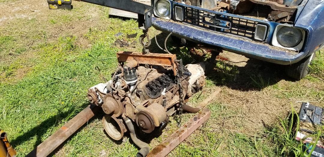
Engine and tranny on the ground in front of the Mustang body.
Engine bay void of powertrain, ready for next phase of project.
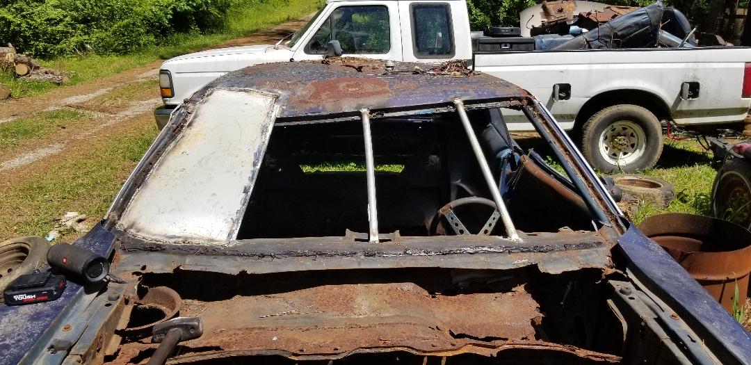
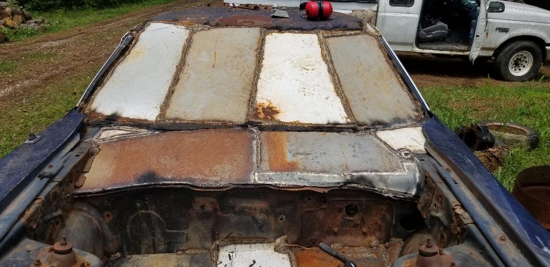
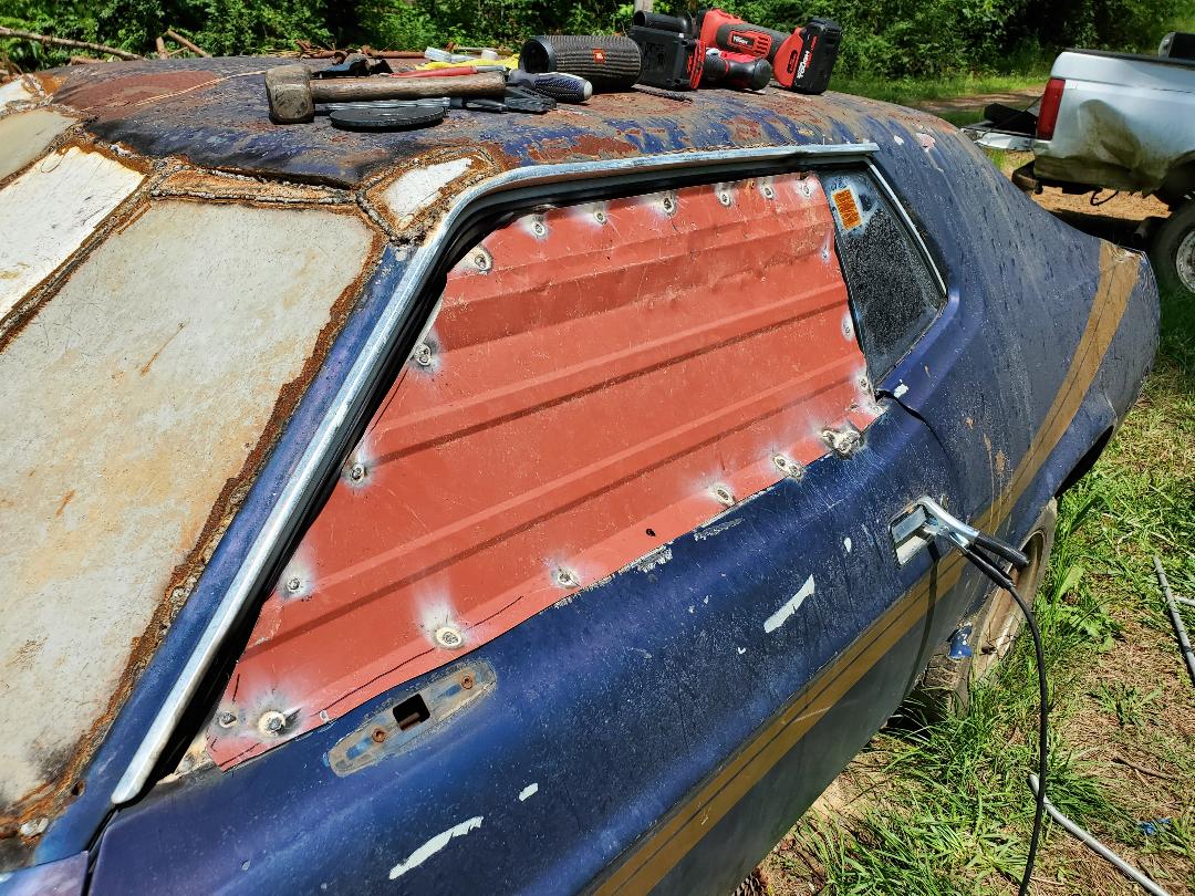
Now the building actually starts on the chicken coop part of the project. I started with the windshield as part of the drying in of the car body. Since the scrap metal that I have on hand is small pieces, I figured that I will have to weld in some pipes to divide the windshield frame into sections. I decided on three pipes to divide the frame into quarters. I have several pieces of conduit to help me in this part The first thing I did with each piece before measuring out the pipe to cut was to cut the end out at an angle so when its rested against the bottom of the windshield frame it will rest nicely on the groove at the top of the windshield frame. As for the passenger side where the roof was still dented in from the tree damage, I cut the pipe longer than the other two so it will overlap onto the roof. The sheet metal that will go over the two right quarters will also be cut longer to overlap onto the roof also. This way the sheet metal covering won't appear to be lopsided. It will at least seem somewhat level. After cutting the pipes I welded them in place, evenly spaced into the quarters as previously mentioned. Now for the sheet metal.
Pipes welded in place over windshield into evenly spaced quarters, note passenger side pipe overlapping onto roof.
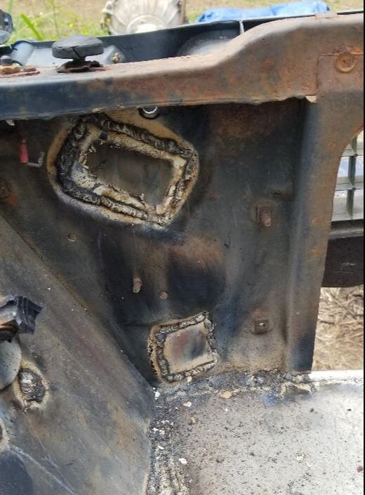
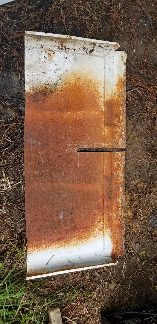
The donor piece of sheet metal was a dryer panel that held the door. There was a section that was large enough that after I cut around the edges I was able to get a nice large piece of metal that was able to fit over the passenger side quarter. I marked the edges with a marker to compensate for the curves of the windshield frame so the panel will fit nicely in the opening. With the sheet metal piece cut to fit I began welding. I went around the outer sides of the metal piece, including the section overlapping the roof. From there I welded a bead along the pipe to secure the sheet metal to the pipe. When I weld in the next piece of sheet metal I will weld a bead to join the edges of the two pieces to ensure a nice weld from top to bottom. This is necessary in order to ensure the windshield covering is watertight all around.
Sheet metal welded over passenger quarter of windshield covering, note overlapping of sheet metal onto roof. Also note curvature of edges where metal was trimmed to fit windshield frame.
With the first panel welded in I moved on to the next section to the left. Cutting another section of sheet metal and trimming it accordingly, I welded around the whole perimeter, getting it sealed in. I moved on to the next panel but not the very next one over. I went to the left-most panel (driver's side). Even though I eyeballed the panel and made sure to trace out the new corners and edges, I still ended up getting the panel measurements off by just a little bit. I ended up having to cut a small piece of scrap metal to fill in the gap that was present. After welding in the "plugs", I moved on to the last panel. On this one I ended up taking measurements at the top and bottom then the length of both sides in order to draw out a panel on another piece of sheet metal. Even after cutting out the panel I still ended up having to trim a couple of edges in order to get the best fit. I started welding in the final panel but ended up having to fight the overheating welder which kept tripping out. After a while I ended up having to just put short sections of weld in place in order to hold the panel down. When I finish the rest of the welding on the windshield panels I will be moving on to the engine bay. I have to remove a couple of old brake lines and the speedometer cable just to clear the remaining clutter from the engine bay. I will be starting with installing pipes that will hold the floor panels.
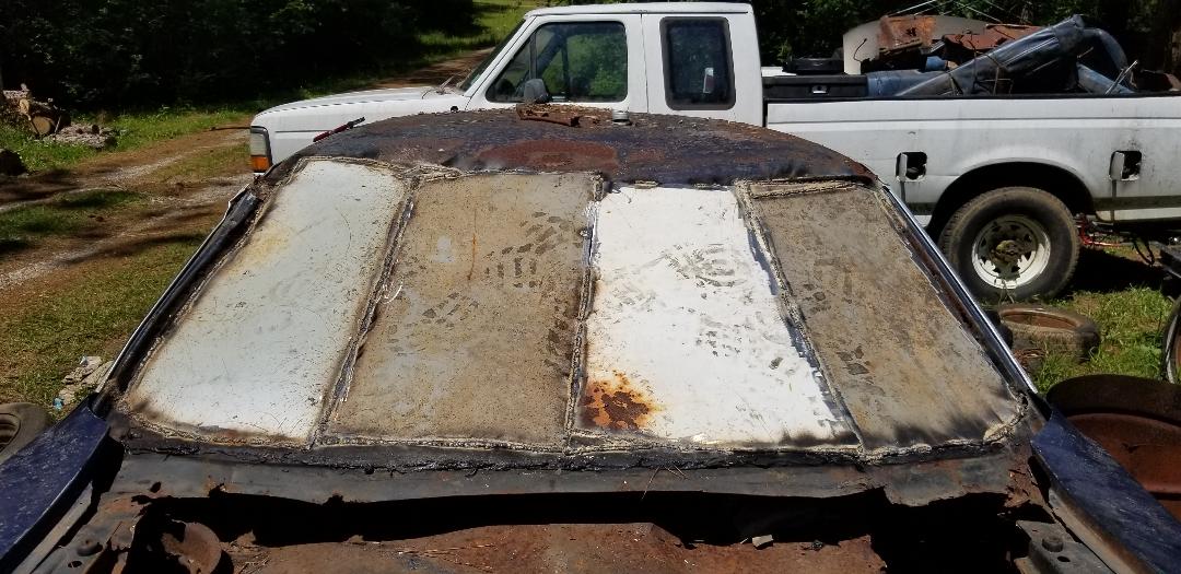
Windshield panels welded in place with the exception for a few spots.
Inside shot of windshield panel covering, note light shining through gaps where panel still needs finish welds done.
With the windshield done on the Mustang the next stop is the engine bay. Since I have adolescent chickens that are needing to go into some secured coops, this made sense to be the first place to start working, especially since I can move the birds into this section while working on the other parts of the overall chicken coupe.
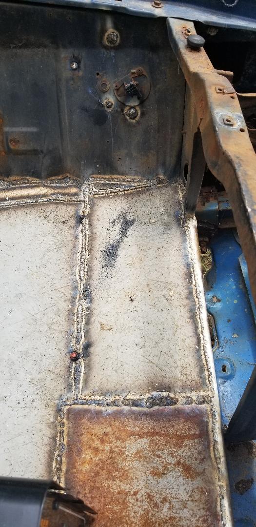
The first thing I did was weld in a piece of pipe just behind the shock tower and just above the steering gearbox. I didn't want to put the pipe lower where I would have to weld in some type of cover to go around the gearbox so it made sense to just put the pipe high enough that the sheet metal that will go on the pipe will cover the gearbox.
The first sheet metal that I choose to use was some drum tops that were cut out from some old burn drums. I had to cut rectangles from these circular pieces of metal and after measuring the space between the pipe and the firewall. It ended up taking three pieces of sheet metal, cut from three drum lids to cover the first section of the floor in the engine bay. I didn't fully weld the metal along the firewall since the firewall has an irregular pattern, not straight. I welded the spots where sheet metal made contact with the firewall. The gaps that are present I plan on sealing with some tar or maybe some of that expanding foam.
First section of floor attached to first pipe welded in place.
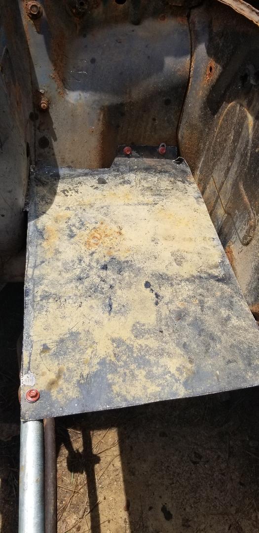
Closeup of first piece of sheet metal secured in place with self tapping screws prior to welding.
Second piece of sheet metal welded in place on pipe.
First section of floor all done.
With the first section of floor taken care of I moved on to the next section. This of course started with another piece of pipe, welded just in front of the shock tower. I had to make sure that the level where the pipe was to be attached would have the floor be as level as possible and not uneven where water may pool in a low spot. With the pipe welded in I moved on to the floor panel.
Second pipe welded in place just in front of the shock tower.
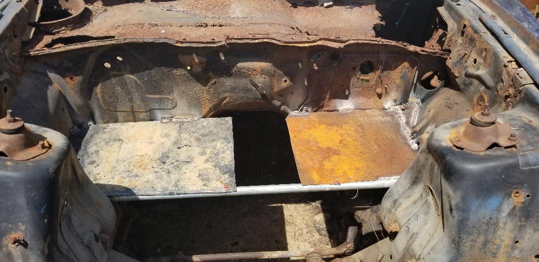
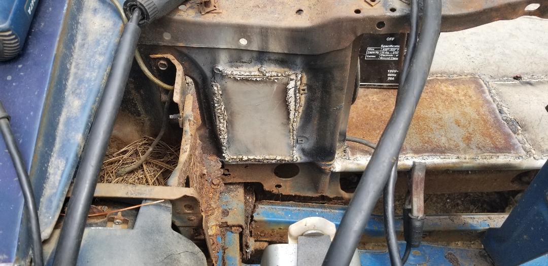
Instead of using another drum top or two or three for the floor I chose a piece of sheet metal that was actually the side of a filing cabinet. The metal actually had a couple of braces underneath that would end up being a problem. After measuring and cutting the section of metal I had to trim out some of the braces under the sheet metal at either end so the piece of sheet metal will overlap onto the pipe nicely. The seams that were welded were nice and clean with no elevated sections or anything uneven. The metal covered about 4/5 of the area to be covered. I'll just need to cut a small piece of metal from some final scrap to finish this section of the floor. The engine bay brooder section will get done pretty fast.
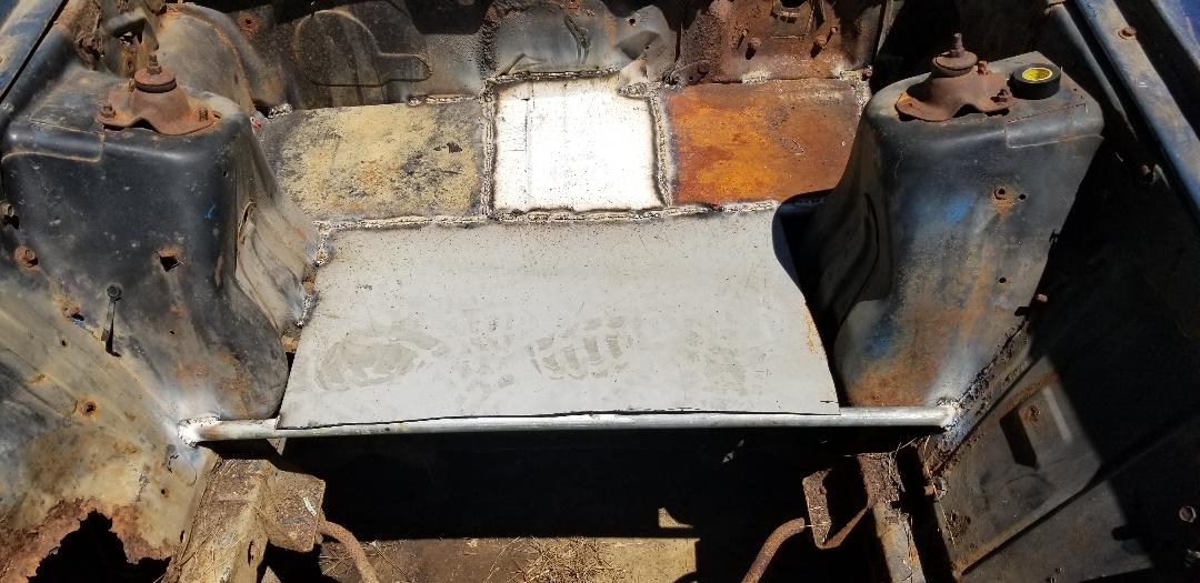
Piece of sheet metal welded in place over second pipe, note gap on driver's side.
After having taken a break from working on the Mustang Chicken Coupe for several days I decided it was time to get back to work on the project. I had to finish up a small area in the 2nd section of floor before moving on to the 3rd section. I had to weld in a very narrow piece of metal to fill this gap.
I attempted to try and cut a single piece of metal to fit in the gap but when I tried to fit the piece in I ended up finding out the shit didn't fit. I ended up welding in a section of the metal, cutting it, then situating it in a way where it would fill most of the gap. I ended up filling in the remaining gaps with slag to finish things up with the remaining gap in the 2nd section of floor.
Final piece of metal patch welded in place to finish up the second section of floor. Note how section is actually two pieces of metal.
With the 2nd section of floor done I measured and cut another section of conduit to weld in place for the 3rd section of floor. Now because the passenger side of the inner fender was rusted out, I would have to come up with an idea to secure the pipe on that side. I went ahead and supported the right side of the pipe with a soup can while I welded the left side in.
With the left side welded in I did some light shitty tack welds in the rusty metal to be able to hold the pipe in place while I started on the actual floor panels. I welded and screwed in a small section of sheet metal at the end to secure it in place on the pipe. With the metal in, I cut a piece of the donor metal panel I used where the metal bent 90 degrees. I wanted to basically make a piece of angle iron that I would weld to the end of the sheet metal panel and to the inner fender where there was still some decent metal.
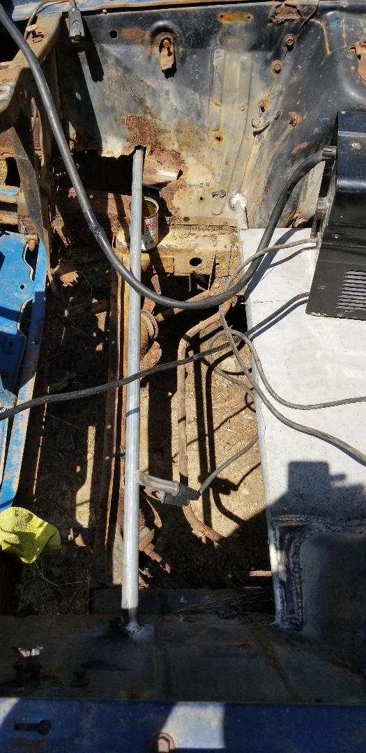
Conduit welded in place at bottom of pic and supported by soup can on top of pic. Note rusty panel at top of pic.
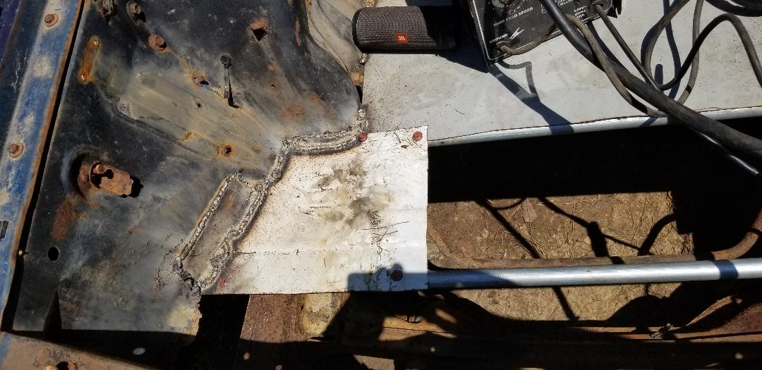
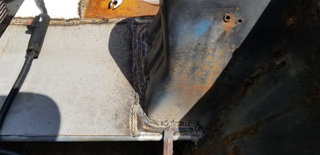
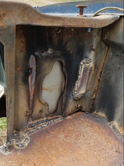
First piece of sheet metal welded in place over conduit for third floor section. Note angle sheet metal piece welded in place between sheet metal floor and inner fender panel to support it in the absence of usable metal due to rust.
With the first piece of sheet metal in place along with the alternative support for the pipe taken care of I found a piece of sheet metal that was already cut in a way where it needed very little to make it ready to fit right in the gap between the conduit and the end of the 2nd floor. I just had to cut the ends of some "interior" braces since this piece of sheet metal came from a filing cabinet. After cutting out the ends of the braces to allow the sheet metal to sit nicely in its home between the conduit and the end of the 2nd floor, I went ahead and used sheet metal self tapping screws in multiple spots to help secure the sheet metal panel to the conduit and to the end of the 2nd floor. There were still some spots that could use some light welding so I did go ahead and burn some metal in those spots but the main support of this piece of sheet metal was the screws.
Large piece of sheet metal secured in place with self tapping screws and some welding. Note gap on right side of pic between the sheet metal and the inner fender on that side.
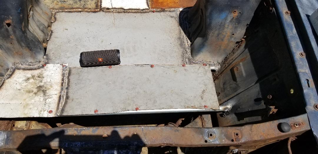
As can be seen in the pic, the third section of floor is almost done, with the exception of a small section/gap that needs to be filled in with a final piece of sheet metal, just like the 2nd section of floor. With the 3rd section done I will move on to the final section, which will put me against the radiator support panel. This will be the last section of floor in the engine bay. With the floor done I will then add a section of sheet metal on the front of the radiator support panel that will be angled downwards to meet up with the front valance panel, with the intent of making a ramp that will allow us to sweep wood shavings/mulch from the brooder down the ramp and outside of the car on the ground. A container of some type will be placed under the valance to catch the mulch that is swept out. Things are moving along pretty good.
Just like with the 2nd section, I had to finish the 3rd section with a small piece of metal on the end. Of course this was pretty easy, just a little bit of welding to get the metal in and set. With the 3rd section done, it was time for the 4th and final section of floor in the engine bay. This was the section going up against the inside of the radiator support panel.
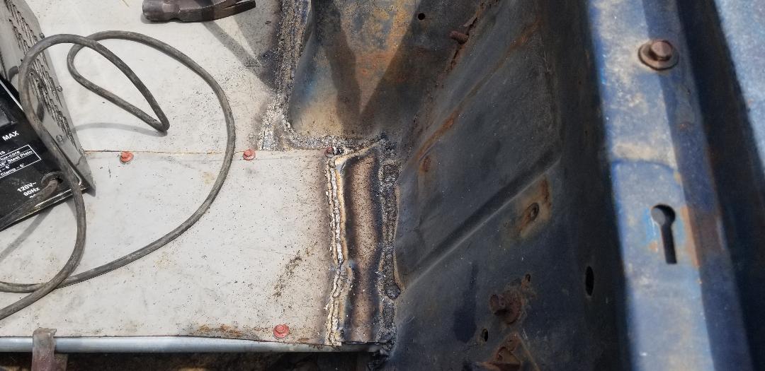
Last piece of metal added to 3rd section of floor.
I cut a piece of pipe to fit in the center of the radiator support panel from the outside. There was a cavity that would hold the pipe nicely so when I weld in the sheet metal, it would be relatively straight, all the way across from right to left. I welded it in and moved on to the sheet metal. Time to find a suitable piece to go in.
4th section pipe welded in place in radiator support panel, note how pipe is in from the outside of panel instead of against the inside of panel.
I measured the width of the opening and found a piece of metal that would allow me to cut a nice clean piece that would fit the width needed. I was able to cut a piece of metal that was long enough to almost cover half the distance from right to left in this section. I had to cut a small tab in the middle of the piece to go around one small spot in the radiator support panel so the sheet metal would sit nice and close to the panel so I can weld the sheet metal in place with a minimum of slag to fill any gaps. Since I already had the self tapping sheet metal screws going through a piece of sheet metal and the conduit, I decided to just weld the sheet metal all the way through.
1st piece of sheet metal welded in place for 4th section of floor.
There wasn't much left to really finish up the rest of the floor in the engine bay of the Mustang Chicken Coupe. I just had to cut one good piece of metal to fill the opening for the 4th section of floor. Of course when I do these rough measurements, no matter how close I get the measurements, if I don't make some kind of template using cardboard, I will end up being off a little bit with the cuts on the piece of metal needed. This was the case, again.
I ended up getting everything right all the way up to the last inch of metal, and with a slight angle to the edge of the piece of sheet metal. I went ahead and welded in the sheet metal as neatly as I could to the rest of the edges and the pipe. I ended up cutting a piece of sheet metal in a triangle shape, just a little bigger than the size of the opening so I can fill that remaining gap neatly. Welding it in was no big deal.
2nd piece of sheet metal welded in place for the 4th section of floor.
With the floor all done I moved on to plugging a bunch of openings in the radiator support panel since this area is going to be for baby chickens that can easily get through some of the openings in the panel. There were also other small bolt holes and other similar openings that I wanted to plug up, mainly because I want to seal up any means for birds to escape and ultimately, any means for pests to come in. I want to keep mice, rats, snakes, and even wasps from being able to get in and wreak havoc within the metal confines of the engine bay.
I cut some small pieces of metal for the larger openings in the radiator support panel and the smaller holes I just filled them in with weld slag. After filling in all of the little holes I moved on to welding in the patches over the larger holes.
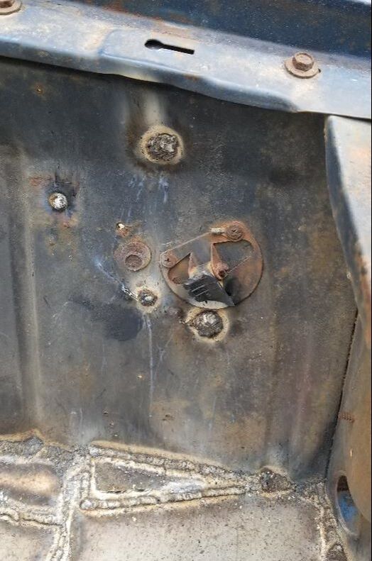
Small holes filled in with weld slag.
Left side radiator support panel patches welded in.
Welding the patches went pretty quick as this was just a simple act of burning exposed metal all around the pieces to secure them, no load bearing metal, nothing to be watertight, just some simple crude patches. With the patches done, the waste removal chute will be the next thing on the agenda.
Outside shot of the right side radiator support panel patch welded in place.
Inside shot of right side radiator support patches welded in place.
Some other areas of the engine bay where there's gaps will be filled in with some expandable foam or something similar that can be wedged in the gaps and not be degradable by water or heat or pecking birds. Some of these areas are rust holes that because of the rusted weak metal, welding is not an option. Other areas because of how the area is formed, it would take a lot of welding to secure even small pieces of metal to help fill the gaps. Main goal is getting all of the easy areas welded up first with the alternative patching being the last thing to do to finish up the brooder section of the car body. I do look forward to getting this done as there are some more baby birds en route and I wanna be able to put this thing to use with those birds versus having them in a brooder box in the house.
I'm now in the home stretch with the brooder portion of the Mustang Chicken Coupe. I have what I've deemed the waste chute to put together, as well as welding up a cover for the rusted and cut out area over the firewall where the wiper motor and linkages used to be. First is the waste chute.
To start this I measured and cut a piece of sheet metal from one of the raw scrap pieces to serve as the actual waste chute. An appliance panel, probably an old washer, supplied a piece of sheet metal with lipped sides that actually worked to my advantage. By cutting a section from the panel, I had a lip on either side to serve as the guide for when waste is swept from the brooder. The third lip was pounded flat to serve as a spot to weld the panel to the front pipe at the radiator support panel. I did have to cut an opening in the middle to accommodate the hood latch brace as well. With those few things done I had my waste chute ready to weld in place.
Sheet metal for waste chute cut and prepped for welding in place, Note lips on top and bottom of pic and the third that was flattened out on the right side of pic.
I arranged the panel where the back lip overlapped on the front pipe as mentioned, welding it in place. After doing that weld I bent the panel at a downward angle to where the panel was touching the front valance and went ahead and welded the panel at the middle groove where it went around the hood latch support. This way the panel retained its downward angle and the overall rigidity was enough to keep the panel from being moved easily. With the waste chute done the next thing was to set up the radiator opening to accommodate a removable door.
Waste chute welded in place. Note the welds on the hood latch support that help keep the chute pointing at a downward angle.
Frontal shot of car with waste chute showing under bumper and behind grille.
For the tracks/guides I cut two pieces of sheet metal that were an inch wide and the length of the height of the opening in the radiator support panel. With these pieces cut I welded them in place as straight as possible. With those in place I then put the power tools to the top of the radiator support panel to cut an opening approximately an inch wide that ran the span of the opening in the middle of the radiator support panel. This opening will allow for the sheet metal panel that will be the removable door to be able to be easily removed from the top.
Tracks/guides welded in place on either side of radiator opening to accommodate the removable door.
The next thing was the actual removable door. Just like with the waste chute, I found a nice piece of sheet metal that could be cut to the measurements needed to make the door. After finding a piece that needed minimal cutting due to one of the dimensions already meeting the criteria for my door, I cut the piece and bent the last few inches of both corners on one end of the panel, to serve as tabs for easier removal. With this being raw sheet metal, until I get some kind of protective covering over the top, the tabs will at least allow for a somewhat safe removal without cutting one's hands. I will probably epoxy some fuel hose over the edges, cutting the hose lengthwise to slide them over the top of the panel. Anyway, the panel slide right in, no problem. The opening was covered pretty nicely and in turn, has the waste removal portion of the brooder finished (minus the protective coverings mentioned).
Waste chute removable door in place, note folded down top corners of panel.
Removable door pulled halfway up to show proof of concept.
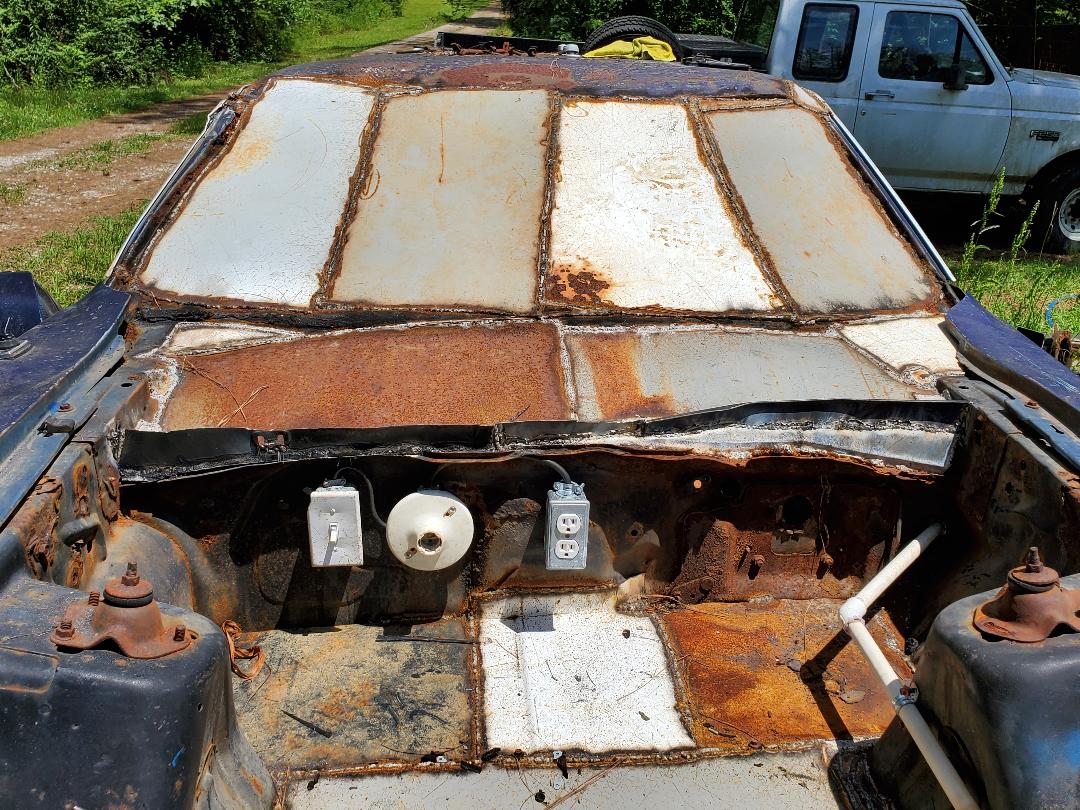
Lastly I wanted to cover up the large opening that was left above the firewall after cutting out the rusted metal and removing the wiper motor and its associated wiper linkages and blade bushings. This was somewhat easily accomplished as all that was really needed was to just cut and weld in a few large pieces of sheet metal. It really didn't have to be neat, just effectively cover the openings since this will cover the opening that can allow baby birds to make it into the main coop area, plus it would just be neater to cover these jagged shitty areas. I started with a good sized panel on the passenger side. After getting it welded in I cut another panel for the driver's side. The driver's side was slightly different where the inner fenders terminated at the firewall so I ended up welding one large piece of sheet metal in that was at the top, then cutting another piece of sheet metal that I actually had to cut in half partway after welding one side of the metal to the firewall. After some more cutting and welding of the edges of the sheet metal I was able to get the whole area covered up pretty good. The only thing left to do with regard to finishing up the places where metal joined metal is to seal those small and difficult to reach places with some roofing repair tar that is applied from a caulk tube.
Firewall panel welded up with sheet metal to help fully enclose brooder area.
With the brooder section done as far as welding is concerned, the next move, as mentioned in a previous post, will be the installation of the electrical box for the heater outlet as well as a light fixture. I will check on my plumbing supply stocks and see if I can get the plumbing installed in the brooder section, complete with the automatic watering cups. I will also apply the caulk tar after getting some from the store later on.
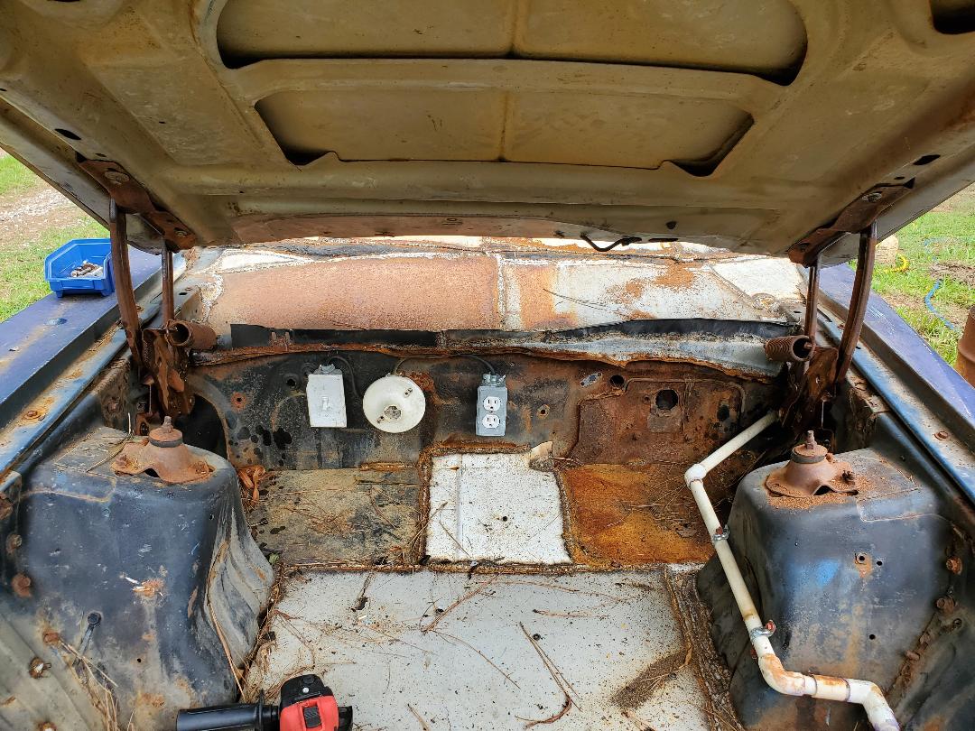
Now I finally get to start installing the electrical and water systems in the body. Of course I started with the engine bay as the floors are done. I had to think about where the best place would be to install the electrical boxes. I ended up deciding on the firewall as this area would allow for the heater to distribute the heat evenly from back to front. The light fixture would go next to the outlet box along with its switch. The light fixture is good on the firewall for the same reasons as the outlet box for the heater.
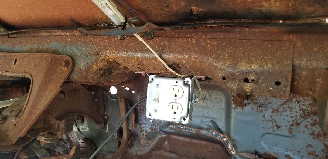
I started with the outlet box. Using the self tapping screws I secured the box to the firewall then went ahead and got the outlet ready for installation. Using a length of 3 conductor cable salvaged from an old cord, I hooked up the outlet and routed the cable through the fitting in the box before securing the outlet in the box. A cover finished off the whole outlet setup. Moving on to the light fixture and its box.....
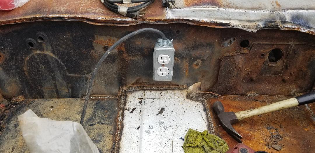
Outlet box with outlet installed, note cable protruding from box.
I went ahead and repeated everything with the box for the light fixture. Securing the box with the screws, I then routed the cable from the outlet box over to the light box, trimming it down before wiring one side to the terminal. I had to keep the other side open since it has to go to the switch box. The light box was also installed at a spot where a hole already existed going into the cab. This will allow me to route a cable to the inside to hook up to the outlet box
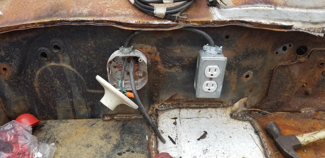
Installing light box with fixture dangling from wires prior to installing switch box.
I stripped the cable that I routed through the firewall and hooked the grounds from the outlet box and the cab cable together. The neutral/white wire from the outlet cable and the cab cable were hooked to one side of the light fixture so the fixture would be in a parallel circuit in the chain, leaving the hot/black wire, to be hooked up to the switch.
I installed the switch box on the firewall next to the light box and installed a 2 conductor cable between the switch and light boxes. I hooked the black wire from the switch cable to the hot/black wire that was still open. The white wire in the switch cable went to the open terminal on the light fixture. With that done I hooked the other end of the switch cable to the switch and secured everything in place with its associated cover. With that, I moved on to the cab.
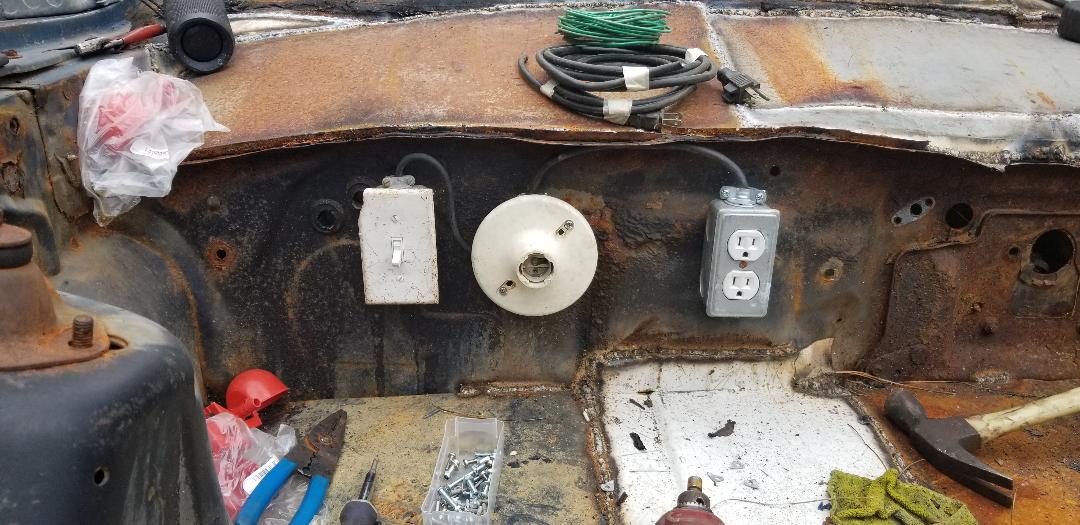
Switch box and switch installed along with light box and fixture and outlet.
Inside the cab I utilized an outlet box that has tabs for nailing to a stud in a wall. These tabs allowed me to screw the box to the underside of the inner dash area which remained after pulling the dash panel and HVAC box out. With the box hanging in place, I installed the associated plugs in the box and routed the cable from the firewall to the box to prepare it for the switch and outlet that I'll install in the box to kill two birds with one stone. Rather than install two separate boxes (which I didn't have now), I installed one large box (which I did have plenty of). Since I needed to get more outlets and switches, the electrical part of this project was concluded for the day.
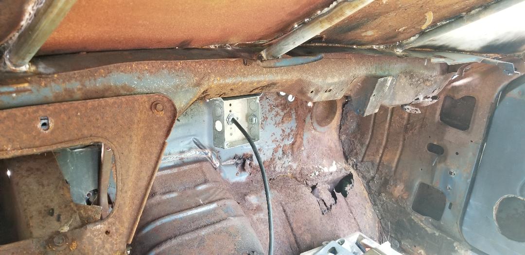
Large junction box secured under inner dash, note cable from firewall routed through back of box.
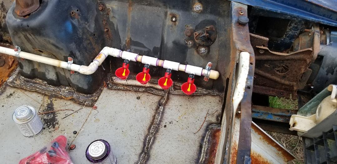
Now for the plumbing. I had to figure out where the water fixtures will go. These fixtures are little plastic bowl shaped things with hose nipples and a single mounting point. The little valve inside the unit will automatically come on until the bowl fills with water and the weight of the water in the bowl makes the bowl lower enough to turn off the valve. I will have to test later on what pressure will be needed to keep the whole thing from just blowing open and failing.
I ended up settling on installing two fixtures on the inner fender between the front of the shock tower and the radiator support panel on the left side. Reason for this was because there are a couple of large holes on the driver's side that would allow for the PVC pipe to be used to be routed between the mounting point of the water fixtures and said holes in the firewall.
Using some 45 degree couplings and some short cuts of 1/2" PVC I did a short run from the shock tower over to the firewall and into the cab. At the cab there is about 2' of pipe going inside. At the shock tower I added a 90 degree coupling with a threaded end to screw in a short threaded nipple with a brass hose barb screwed to the other side. From here plastic hose will be connected from the nipple to the nipple of the first water fixture. Another short piece of hose will link the two water fixtures together. I will have to put a final short piece of hose to the nipple on the last water fixture and plug it with a bolt to terminate the water line run.
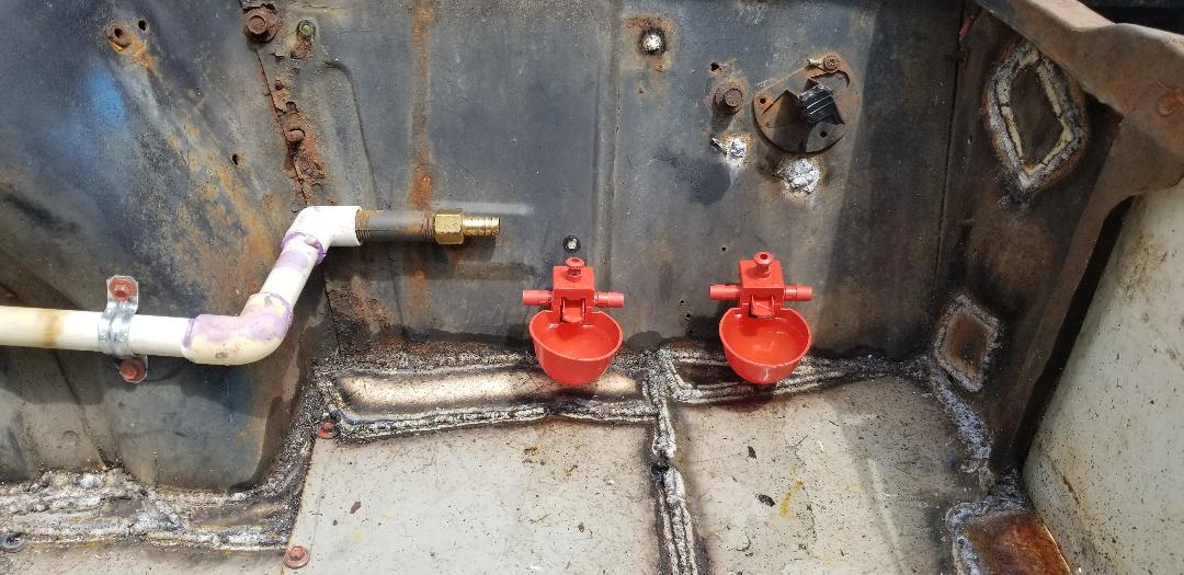
Water drinker cup fixtures secured on inner fender.
PVC water line routed from firewall to water drinker cups, note straps holding pipe in place and brass hose barb on end.
After making another supply run I was able to get many things done on the electrical system and the plumbing. My intent was to get the whole electrical system done and get the brooder section of the water system hooked up, based on what I had in my supply stash.
First thing I did was cut and hook up the hoses for linking the water line nipple to the nipples on the drinker cups. Three hoses and some clamps and a bolt had the whole system linked together and capped at the end, ready to accept pressurized water. This was quick and easy so it was on to the electrical system, starting in the cab, well really staying in the cab for all intents.
Water drinker cups linked with clear hose, note bolt at end of line plugging system.
In the cab I finished up the outlet switch box that was installed under the inner dash. The cable routed to said box was prepped and hooked up to the outlet. The next thing was to run a small jumper from one of the terminals on the switch over to the hot lead on the outlet. Next move was to run a 2 conductor cable from the outlet box up the windshield and back to the brace where the old dome light was. After putting enough wire in place I wired one end to the other terminal on the switch and the other side to the neutral terminal on the outlet. Before capping off the outlet/switch box I took a length of cable with a plug on it and hooked it into the box, wiring it up to the hot and neutral terminals on the outlet. With that done I secured the outlet and switch to the box cover and screwed it to the box.
Cab outlet/switch box hooked up, note cable running up windshield towards light and cable on side hooked up to power plug
Now for the light box. As with the other junction boxes, this box was secured to the dome light brace with self tapping screws and the wire secured in place through its associated fitting. Wiring the light fixture and securing it in place finished up the electrical system. I just needed to put a couple of light bulbs in place to test the fixtures, along with using the drill in the outlet to test those.
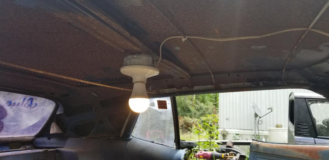
Cab light hooked up and working just fine.
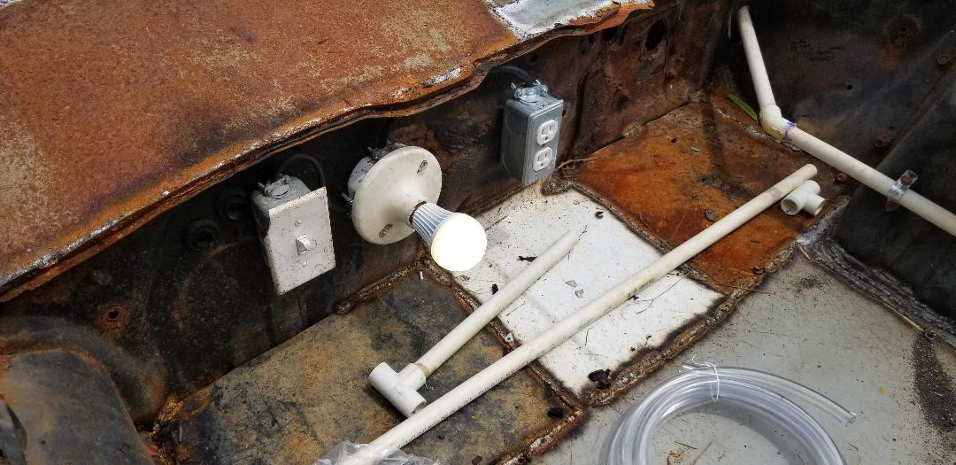
Engine bay/brooder area light working just fine.
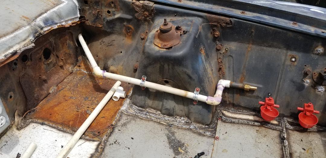
With everything working as designed (in my head), I can now turn my attention to finishing up the plumbing in the cab. This will involve trimming the pipe in the cab and routing it to a spot farther under the dash where I can hook up some more drinker cups, but of a different design. The cups will be the kind that thread into PVC fittings that will be attached to a main water line to be neat and secured within the cab.
The cups and PVC tees came in at the same time I got started with the interior floor. I ended up having to get another welder as well. The new welder turned out to be way better than the old one ever was. I welded in a pipe and started welding in sections of sheet metal to get the first section of floor done around the transmission hump. Again, the welder surpassed all expectations. After getting the tranny hump done I used more self tapping screws to secure the panels to the pipe, to the inner rockers and to each other.
First section of pipes welded in place around subframes and tranny hump.
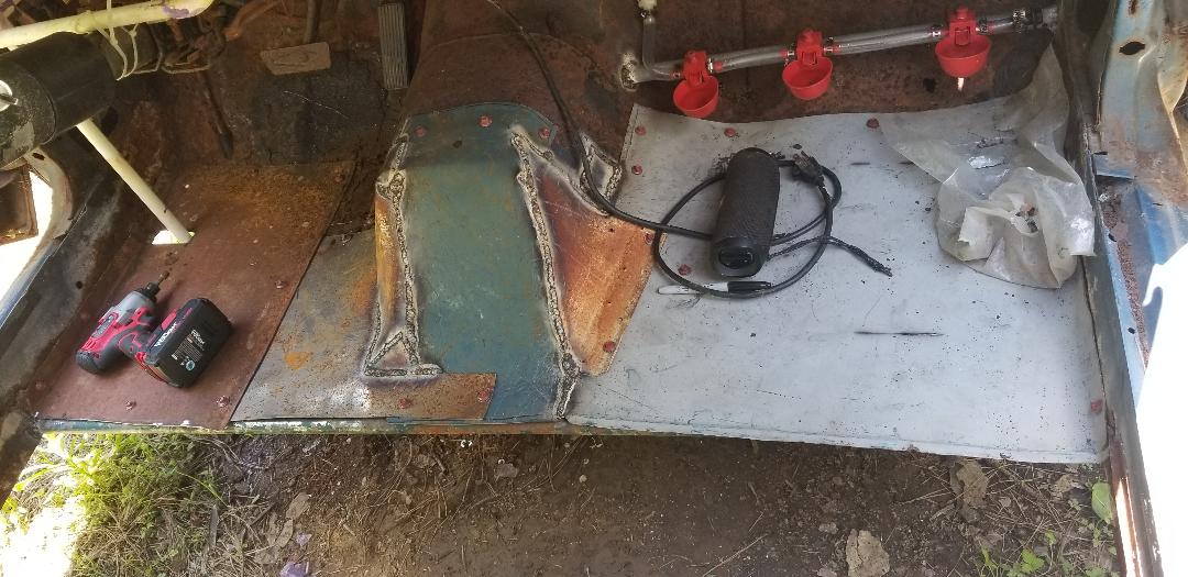
First section of cab/interior floor done, note patches around tranny hump.
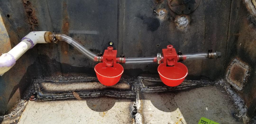
With the first section of floor done I went ahead and installed the new drinker cups. I removed the old drinker cups and hose and did some more PVC work to get the ends of the pipe ready to accept the new PVC tees. I assembled the tees and drinker cups as a complete assembly before gluing that to the pipe in the car. With the two assemblies installed I hooked up the hose to test everything out. Things sorta worked but again the water pressure was a little high and it caused a couple of the new drinker cups to pop loose. Others didn't work as they're supposed to due to the excessive pressure pushing on the little valves. At least I have a regulator still en route.
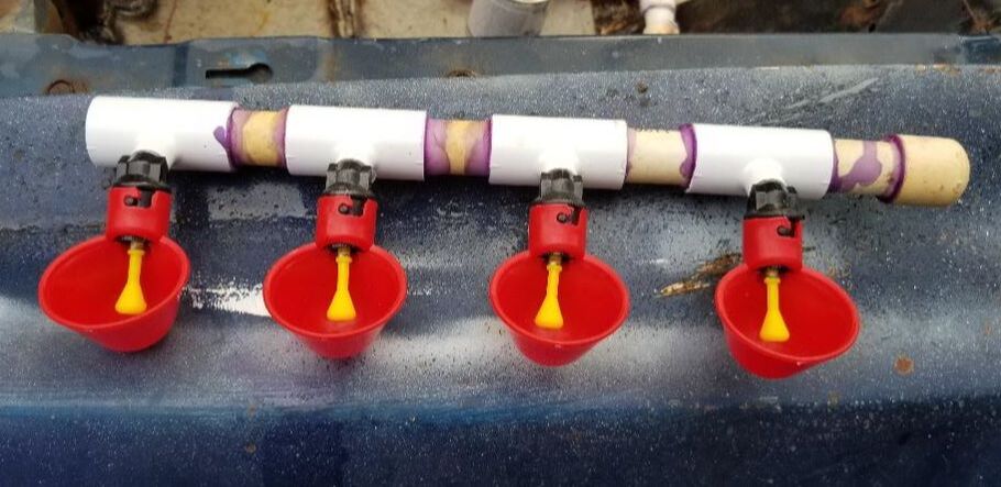
Drinker cup assembly put together and ready for gluing in place.
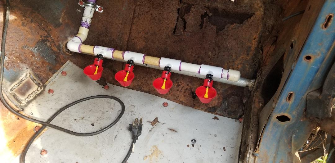
Drinker cup assembly installed in cab.
Drinker cup assembly installed in brooder section.
With the drinker cups done I moved back onto the cab floor. I welded in all the pipes going all the way to the back, spaced in accordance to the sheet metal pieces, and to allow for proper weight distribution when one of us has to crawl inside to do something afterwards. With the pipes in place I started cutting and screwing in sheet metal, trying to minimize the use of welding to secure the panels.
Pipes welded in place in the middle of the floor just behind the first section.
Floor pipes welded in place inside car.
Second section of floor panels secured in place.
There are two levels to the interior floor, the main floor section where the front seats would be, and the rear section where the rear seats would be. There is a rise at that junction of a few inches where the old floor angles straight up then goes back horizontal. I ended the main floor at that point then continued the floor panels from the higher pipe going back, leaving an opening between the two levels of floors. I still had to figure out what to do about a waste chute since I still have to be able to easily remove the mulch when needed. At first I was going to cut a hole in the main floor to install an access panel but with the opening being present between the two floors I figured that would be my best bet for installing some form of waste chute.
Two sections of floor secured in place in the cab of car. Note opening between the floor sections.
I decided to weld in a piece of metal to cover half of the opening then installing another piece of metal over the other half of the opening, using hinges to turn the piece of metal into a door. The hinges were welded to the door panel by doing spot welds using the screw holes on the hinges, then screwing the other end of the hinges to the floor to secure the door in place. I also cut the metal with a lip with which to drive a screw through to hold the "door" shut and secured when not in use.
Trap door installed along with extra panel.
Trap door in the closed position, note screw used to hold door down. Also note hinges welded and bolted to hold door.
With the cab totally done I moved on to the trunk area. I had to weld in some pipes to give me the support necessary to hold the large piece of sheet metal that I cut from a car hood. With the pipes in place I fit the large panel in place and secured it via welding and self tapping screws. With the main piece of sheet metal in place I was able to continue filling in the side areas with smaller pieces of sheet metal all the way over to both quarter panels and all the way to the end of the trunk, ensuring that the trunk floor was completely filled in.
Main trunk floor welded and screwed in place.
With the floor in place I then started making plans for how to make the back wall setup. I figured that I would install a couple of doors side by side to serve as access hatches for the rear area/nesting box. Since the quarter ends are curved in a way that doesn't allow for any kind of normal panel to be installed I had to cut and install a couple of extension panels from the corners, making a sort of "door frame". These of course were just a couple of pieces of sheet metal cut to fit and fully welded in place.
Quarter panel extension panels welded in place on either side where taillights would've been.
After welding in the quarter panel extensions I then went forward and installed a pipe across the top along the point where the bottom of the trunk lid would be when its closed. The purpose of this was to provide an extra door frame support for when I install the panels. I'll need somewhere for the doors to rest and be able to latch up to when in the closed position so the bar serves this purpose.
Support pipe welded in place across trunk area to help build up door frame for access door panels.
Another reason for the bar was because of my plan to weld the trunk lid shut. With the trunk down the bar would be hidden from view and serve as that point for the access doors to latch to. The trunk lid is too rusty and shitty to provide any solid point to latch so that's where the bar comes in. Anyway, the trunk was welded shut. Because of the rust in spots along the trunk lid edges and the quarter panel edges where the trunk lid meets, I couldn't fully weld around the trunk but I did get more than enough of the lid secured. The rust hole openings will have to be filled in with tar just like the many other spots that need to be filled in.
Trunk lid welded shut , note spots where welds aren't present due to excess rust along seams
Just like with the access hatch in the cab, I made two door panels using sections cut from more filing cabinet metal and welded hinges to the corners using the screw holes as spots for the spot welds to hold the hinges in place. The panels were cut where they actually had a seam or fold along the edge that served to make the panel more rigid. the filing cabinets where this metal came from used these folds of metal to make them more sturdy and that feature helped in making sturdy doors for the nesting box area at the back of the car. With the hinges in place on the two panels I secured the door panels in place in the back, ensuring everything lined up so when they close there will be minimum gaps around the doors. Once done everything worked out perfectly. The doors line up nicely and open and close as intended.
Nesting box access doors secured in place.
Hinge spot welded to door panel .
As an aside, I did get my water pressure regulator. I can now install that into the water line so I can see if the drinker cups will work as intended. I had to get a couple of 1/2" male thread to female smooth bushings to install on both sides of the regulator. After installing those I was able to cut the PVC pipe coming up through the floor and remove enough pipe that when I installed the regulator and glued the section of PVC pipe I cut free, the PVC pipe would be flush against the underside of the car where the pipe angles out to the side to accept a hose. With the regulator in place I adjusted it to a spot where it was considered at its lowest pressure and turned the water on. I had to make adjustments to ensure the water is flowing as I need it to all the way to the drinking cups. After doing this, I was able to get the system to work as I hoped it would. The drinker cups do work with minimum pressure not blowing anything apart or otherwise springing leaks. With that I can say the water system is all ready to go right along with the electrical system.
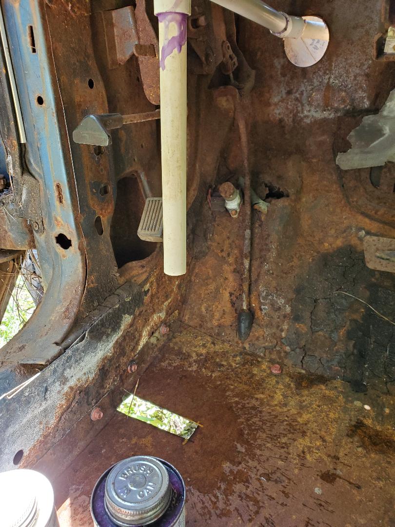
PVC inlet pipe cut and trimmed short to accommodate regulator.
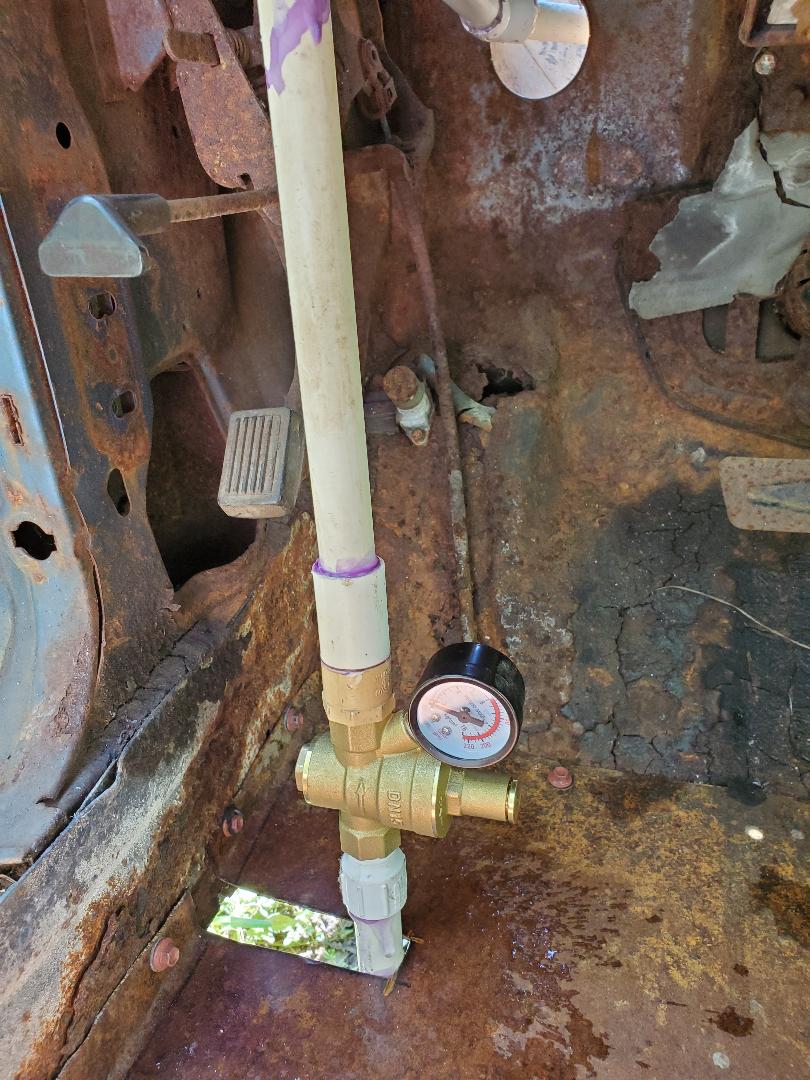
Pressure regulator installed in plumbing line
With the regulator and water line completed I moved on to the firewall area of the car. The plan was to cut and weld a line of panels along the top of the firewall panel with the intent to redirect any water that makes it past the hood, especially since the outlet and light fixtures are mounted on the firewall. Directing the water to the sides where it can run down between the metal panel seams, I can keep the electrical system in the brooder from getting wet and possibly shorting out. TO do this I just cut a couple of strips of metal approximately 2" wide and trimmed them to fit then welded the metal strips in place. With the metal panels in over the top of the firewall I can now move forward with putting the hood back on so I can say I've complete the brooder area of the Mustang Chicken Coupe. There's only a little more to go before we can say this thing is completed
Water diverting lip welded in place along top of firewall
The next thing I had to do was make the door window panel for the driver's side door. Since the driver's side door isn't going to be used in any capacity I planned on making a frame to install a piece of sheet metal to in order to cover the window opening. I was going to weld the door shut but I figured I'll still leave the door "open" in case I had to open it in an emergency to do any kind of work. It doesn't have to be completely sealed but it does need to be covered up enough to keep a driving rain out. I expect leaks to occur as the body has rust holes everywhere and the only way to make the car watertight will be to wrap the whole damned car in plastic wrap. I just want to keep a large amount of water out of the car, and that's where the sheet metal panel over the door window comes in.
The first thing was to make the actual frame that would take the same contours of the old window, which of course does not exist. This was done using plain old conduit. After bending it to the angles to mate it up to the window frame I welded the pipe to the front and back of the door top. I welded up two different pipes, a straight pipe at the back of the door and an obtuse angled pipe to cover the top and forward angled sides. Three welds and the frame was done and ready. I may weld an extra pipe depending on the rigidity of the whole setup later on, we'll see.
Door window frame made from conduit, note weld joints
The next thing was the metal panel. At first I wanted to just cut a piece of sheet metal from one of the larger panels I had in stock but then I spotted a smaller piece of corrugated sheet metal among the other sheet metal and figured "why not use this oddball piece I'll probably never use elsewhere". And so it was. I took the metal and traced an approximate border line for the window, taking into account adding a lip for the bottom to help attach the panel more easily. To attach the panel I used the same concept I used to attach the door hinges, doing spot welds. Of course since there were no holes in the panel I had to drill some. I marked a number of holes along the edges of the panel and drilled them out. With that I was able to do a series of spot welds along the sheet metal to secure it to the pipe and the top of the door. Now that the driver's door is done its time for the passenger door.
Sheet metal panel spot welded in place to the door frame.
Today was rather simple and straightforward, getting the window frame "covering" set up on the passenger side door on the car. Unlike the driver's door, which has a Sheetmetal panel, this door is just going to have a chicken wire fencing covering over the window opening to serve as an opening to the outside without allowing the birds to be able to escape or something else to come inside.
Like with the driver's side I had to start with the window frame. This was done again with conduit pipe, two pieces, one for the back side, and one with an obtuse angle to match the contour of the window opening. These were welded in place to get the initial window frame set up.
Window frame started on passenger side door.
The next thing I did was cut and weld a piece of pipe to weld along the top of the door, at the bottom of the window frame. This piece of pipe was especially necessary since the top of the door is bent in from the tree that fell on it. The pipe will give the window frame that straight bottom portion to help support and hold the chicken wire that will be used.
Bottom piece of pipe welded in place, note bent in top of door from tree damage.
I had to look around for a suitable piece of chicken wire fencing to use. The piece didn't have to be big but I did need to be able to cut enough to be able to fold the edges around the pipe window frame and weld tack points along the bottom on the door. I ended up finding a piece of chicken wire that was attached to a couple of trees from a past project in this section of the yard. I ended up being able to cut a good piece from this. From here I trimmed the piece to fit the window frame and give me a few inches extension at the bottom. I also allowed for some overlapping along the top and back sides of the window frame with the intent on having the chicken wire stems that remained after I trimmed the piece. I was able to bend these little stems around the pipe to secure the fence piece around the actual window frame. From here I carefully tacked points on the fence where the wires crossed in order to optimize the amount of surface area to take the fire from the welder. Of course I burned through the wire on several occasions but was able to salvage things and get the spots secured to the door.
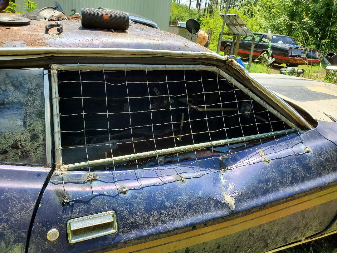
Chicken wire panel bent and welded in place over window frame, note folded wire ends on pipes and tack welds on door.
With the passenger door done I had to stand back and think for a minute what I want to do next. I had the idea to use a dryer vent attached to the sheet metal on the driver's door in combination with a large computer fan to serve as ventilation to pull hot stagnant air from the cab of the car. The fans I do have in stock are 12v fans so I'll also have to dig out a 12v power supply that I can wire into the fan and plug up to the outlet in the cab, a simple accomplishment. Of course I'll still have to pick up a dryer vent but that's no big deal. At the same time I'll pick up the latches I need to finish the rear doors for the nesting box area. I also have to make a little ramp that will allow the birds to walk up to the nesting area from the rear seat area. I still have to figure out what to use for this but it'll get done and this project will finally achieve completion.
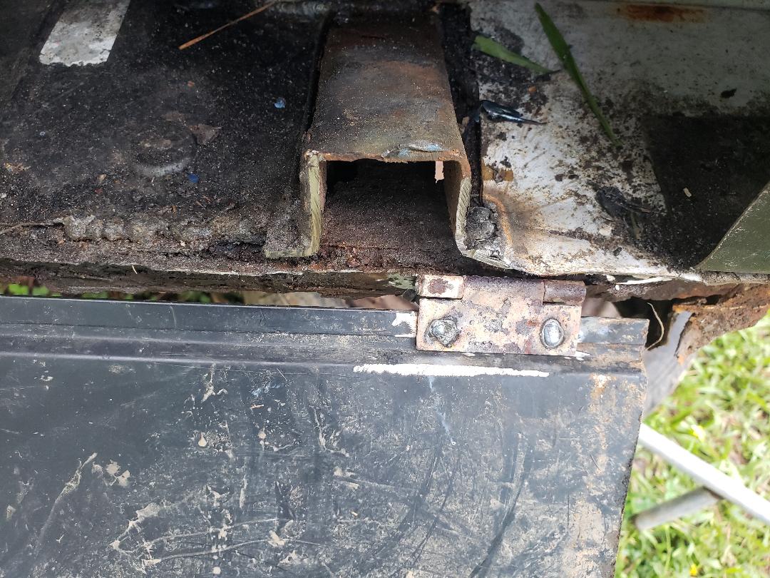
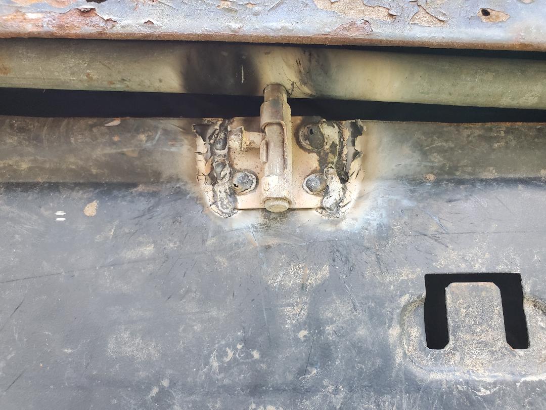
After getting a couple of barrel bolt/sliding latches and a dryer vent I was able to move on to the next stage in the construction of the Mustang Chicken Coupe. First thing I did was line up the latches at the middle of each door and from there was able to mark and drill a hole in the support pipe that I welded just behind the trunk lid and right above the tops of the doors. On one of the bolts because the door was not as lined up with the support pipe as the other side, I had to weld the bolt body where it overlapped above the top of the door. I was only able to use two of the screw holes to spot weld the piece in place so I had to put welds along the edges of the bolt body to fully secure it. I also had to cut a small piece of the trunk lid to accommodate that protruding portion of the bolt body when the door was opened. The pics show everything.
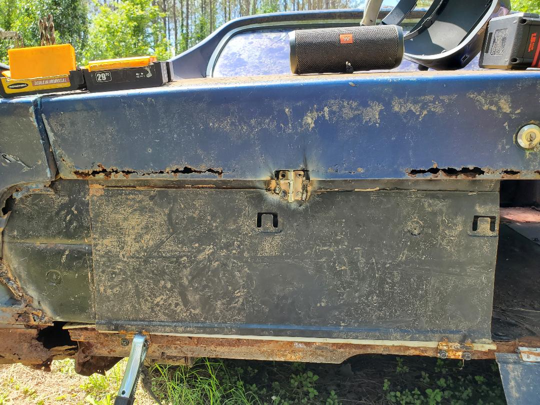
Left door latched closed, note notch cut from trunk lid to accommodate the barrel bolt.
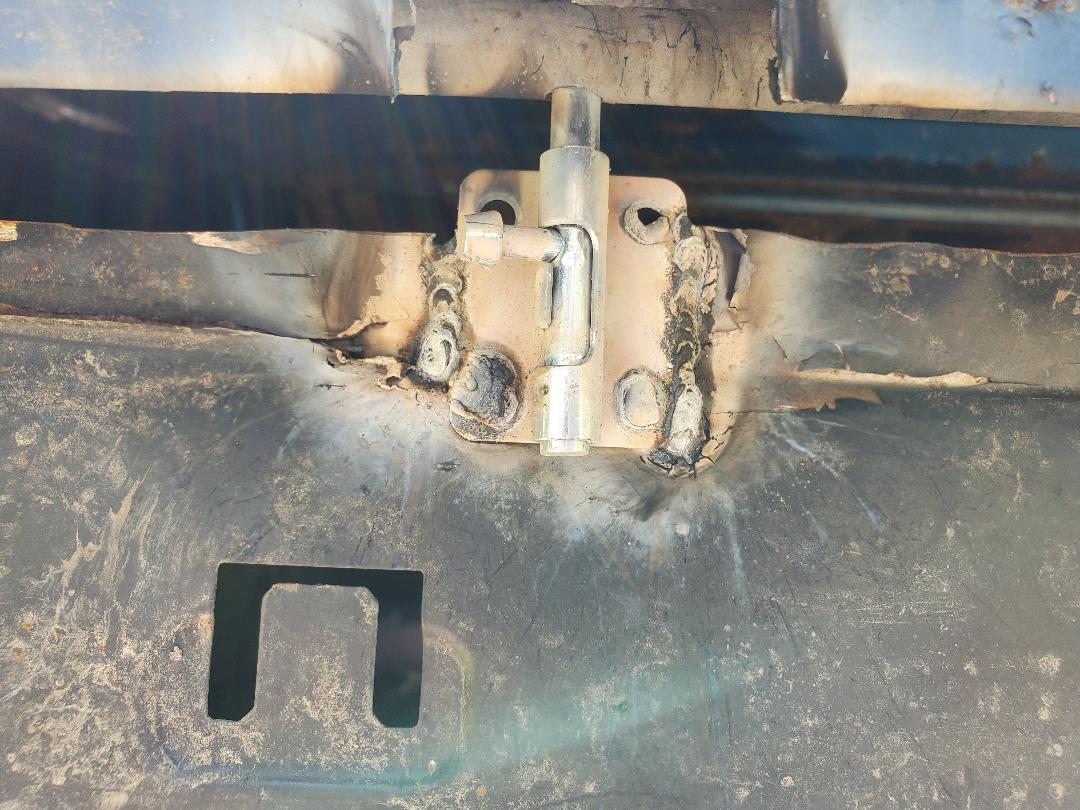
Closeup of barrel bolt latch and notch in trunk lid showing where bolt is inserted into hole in pipe.
On the right door the latch I had was a bit smaller and the support pipe was lined up better so I was able to use all four screw holes to spot weld the piece to the top of the door. I still did welds along the outer edges for extra support. Because the top of the door was closer to the support pipe and the barrel bolt body was lined up evenly with the top of the door, I didn't have to remove any metal from the trunk lid. Guess you can't win em all when fabricating shit, especially with rusty jacked up shit like this.
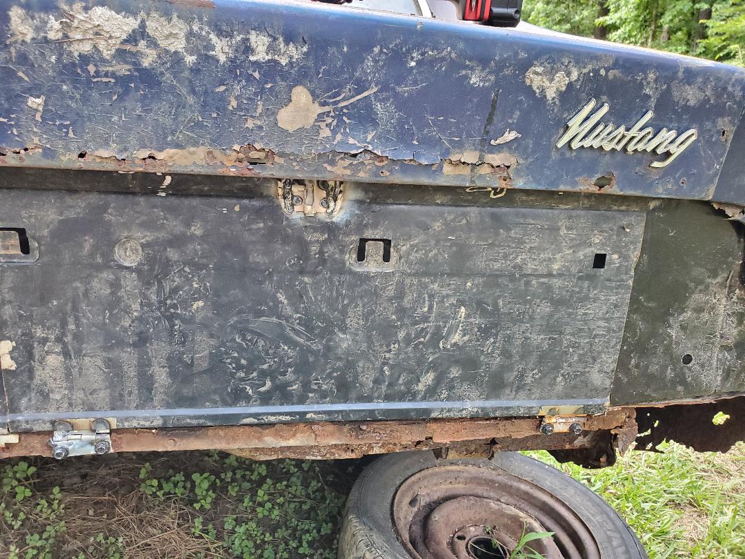
Right door barrel bolt latch in place holding door closed.
Closeup of barrel bolt welded in place and secured to support pipe.
With the nest area doors secured I moved on to the vent/fan assembly. This assembly will consist of a dryer vent with some metal tube attached and a large computer/power cabinet ventilation fan. First thing I had to do was take the metal tube portion of the dryer vent and trace a circle on the window panel on the driver's door. From there I used the die grinder, which since its disc was already worn down, allowed me to cut a decent circle by just cutting a series of cuts around the circle. With the circle cut out of the door, I then took the dryer vent body and removed the metal tube from the vent. I then drilled four holes in the window panel and secured the dryer vent to the panel with screws/nuts.
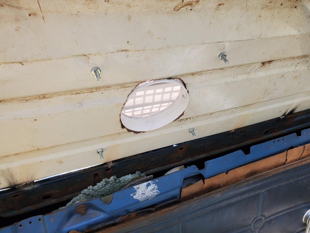
Dryer vent body installed in window panel with screws/nuts.
I took the metal tube and drew lines to make four tabs evenly spaced around the tube, a few inches from the end that snaps into the dryer vent body. I cut the excess metal tube off and then cut along the lines to expose the tabs. I bent these tabs out for my next step. The next step was fitting the fan where its bolt holes line up with at least two of the tabs. I was able to achieve this goal, getting the two opposite tabs lined up with the two opposite screw holes in the fan. I secured the fan to these tabs with more screws/nuts. From here I took some duct tape and used it to cover the gaps that were present between the fan and the metal tube. With that I snapped the metal tube back in to the dryer vent body. Time for the wiring.
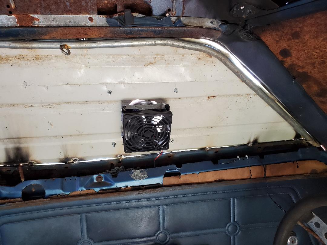
Fan secured to metal tube and installed on dryer vent.
Next was the power supply for the fan. I dug out a 12v power supply I saved from a long dead router, rated for 12v at 1 amp. I plugged it into the outlet and routed the wires over towards the fan to see if I needed extra wire to complete the connection. Of course I did need a little extra wire so after digging out a little bit of 2 conductor wire from my wire stash, I soldered the wires together, covering them with heat shrink tubing. I wire tied the wire to a few spots along its route to keep it all neat and secured. I also plugged up the heater that I used in the dog's house to verify it'll fit with the fan power supply.
Power supply and heater plugged in to outlet and wire for power supply wire tied along top where window panels are.
The last thing I did was prop open the louvers on the dryer vent. Even with the fan running there wasn't enough pressure to push open the louvers. I couldn't think of anything off the top of my head to prop the little plastic flaps open so I just used some of the screws from the barrel bolt. I just drilled three holes on one side just under the open flaps so when I put the screws in place, they kept the louvers open at about 45 degrees angle. With that the fan will be able to move air out in a decent manner and still keep rain from just making its way in if I just had an open hole with the fan on it.
Dryer vent body on window panel.
The next thing I wanted to do is install the hood hinges on the car so the heavy large hood can be opened and closed by either of us with easy. The passenger side hinge had all its bolt clips in place but I did have to cut back the firewall lip I welded in place on a past day in order to accommodate the hinge body. This was pretty insignificant as the area is still able to move water the way I intended.
After getting the passenger side hinge in place I did the driver's side. One of the bolt clips was missing so I ended up just making sure the other two bolts were on tight. With both hinges in place I recruited my help to help me get the hood in position where I could add the bolts to secure the hood to the hinges. After getting the hood on I was able to test the hood out, opening and closing the unit while still having it line up decently. Satisfied with that I moved on to installing another cooling fan but this time on the firewall somewhere and blowing into the main cab.
Hood hinges in place with hood bolted to hinges.
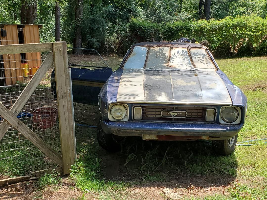
Mustang's hood closed on hinges, note hood lining up pretty good despite distortions from damaged fenders.
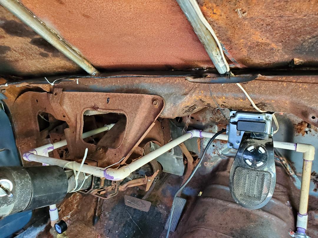
As for the cooling fan, I had a couple more large computer fans in stock I was able to take from. With that I ended up finding that the only good spot to put the fan was over the hole where the brake master cylinder used to be. I did enlarge the circular opening with the die grinder, making a large oval shape so more area was opened up to the face of the fan. I drilled two holes, diagonal from one another, so I can drive some long wood screws through the fan body's mounting points and into said holes. The wood screws' thread has a shallow pitch that allows it to grab into metal easily when the pilot holes are the right size. With that I was able to secure the fan in place over the opening. All I have to do now is find another 12v power supply to power this fan.
Cooling fan mounted in place over old master cylinder mounting point.
I took a pause from the Mustang Chicken Coupe to get other things done. Another storm came through and made another tree come down partially, over the Mustang and its neighbor, our LUV EV. The tree was actually hung in the power line going to the house so it didn't come down completely onto the cars. I ended up having to move both vehicles to clear the way for the power company to come cut the tree from the power line. After they came by and did their work, I had the task of clearing the trees from the area. As for the Mustang Chicken Coupe, I had to move it to a spot along the driveway, downstream from its old resting spot.
After removing the tree and its remains, I had to do something with the Mustang Chicken Coupe as it couldn't remain in its new temporary spot. I decided that it was time to move the car into the chicken yard and to its new resting spot, especially since the ground was plenty dry. I had to start things off with the help of the F250. I hooked up to the Mustang and pulled the car upstream in the driveway. Since the driveway is on a downward grade, pulling it upstream will allow me to use gravity to move the car easily over into the chicken yard.
Using the F250 to pull the Mustang Chicken Coupe up the driveway to stage it for pushing.
I wanted to back the car into the chicken yard so when I park it, the nose of the car is showing from the area next to the other structures instead of its ass end. Again, using gravity, I was easily able to push the car down and around over to the fence to the chicken yard. The double gate I worked into the fence was able to accommodate the car easily.
Pushing the Mustang into the chicken yard through the fence.
Even though I was perpendicular to the downward grade of the land, I was still able to continue pushing the car further into the chicken yard. I just needed to give it a little extra kick to further push the car along. Cutting the steering wheel, I was able to push the car perfectly into its new spot. Its parked next to an old chicken coupe structure and between two pine trees. Since I didn't back the car all the way against the fence line we can still access the rear of the car to get to the nesting area and the space between the two trees gives us plenty of room to open the doors as needed to maintain the coupe. The spot the car rests on is level enough that I didn't have to chock the wheels to keep it from rolling in any direction.
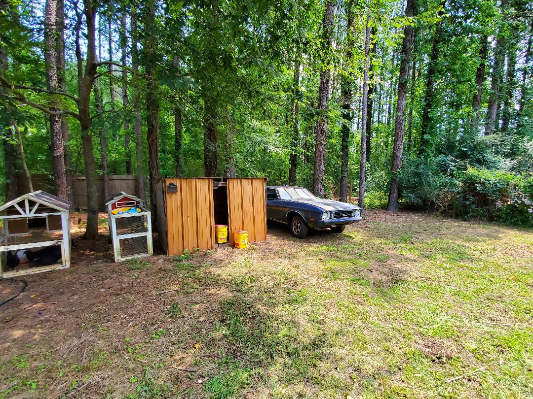
Mustang Chicken Coupe parked next to old coop structure and between two trees, nose sticking out.
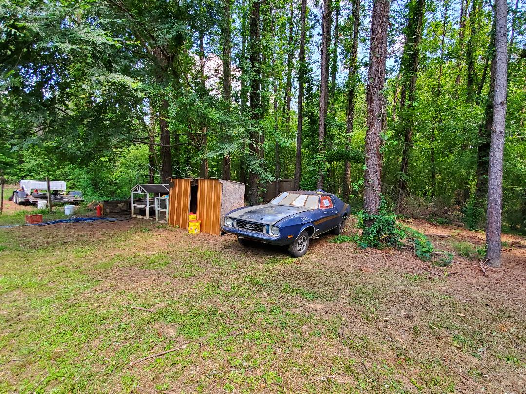
Mustang parked in new home between two trees.
With the car parked in its new home, the next order of business will be hooking up the power and water. I'll be digging a trench from the house and power pole so I can run an extension cord from the outside power box down into the trench and over to the car, much the same way as the extension cord that's running to the dog yard. As for the water, I'll put a tee in the pipe that feeds the spigot for the chicken yard and run a pipe down into the ground and the trench over to the car. Pipe foam will cover this new section of pipe to keep it from freezing. The pipe will terminate at another spigot by the car and a short length of hose will link the car's pipe to the spigot.
I had to move up the timetable for getting the utilities hooked up in the Mustang Chicken Coupe due to the idea that the hatchery we normally order baby chickens from had moved up the ship date for a small order of chickens we had from July to NOW. So even though the car was in position in the chicken yard I still needed to get water and power hooked up. I took care of the water with a simple garden hose but still had to get power to the car. Since it is warm I wasn't really too concerned with power.
I brought the chickens home and we got them set up in the brooder area of the car and showed them the drinker cups so they can get used to where to find water. We put a small bulk feeder in the brooder so they can have a fair amount of chicken feed. Even though things were straight, I wanted to get things permanently set up. This means digging a trench to set up the PVC water line as intended to replace the hose. I also wanted to put an extension cord in to run along with the pipe.
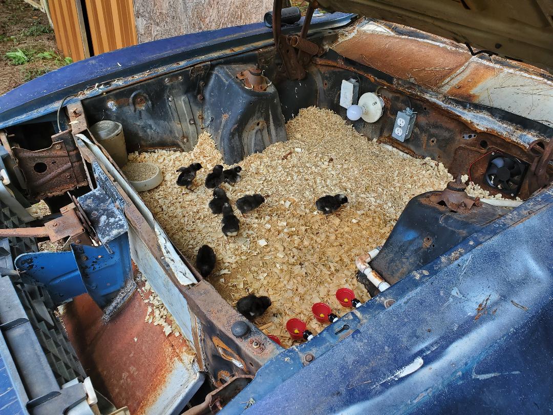
Baby chickens in their new brooder section of the car.
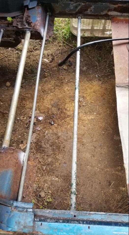
The first thing I did was start digging the trench. I dug a line from the spigot on the house, past the old AC unit then turned at a 45 degree angle towards the car. Once at the car I did another turn to go along side the front left tire of the car where the pipe will end and the spigot will go. I also added a spur from the power pole to connect to the main trench so I can run the extension cord as well.
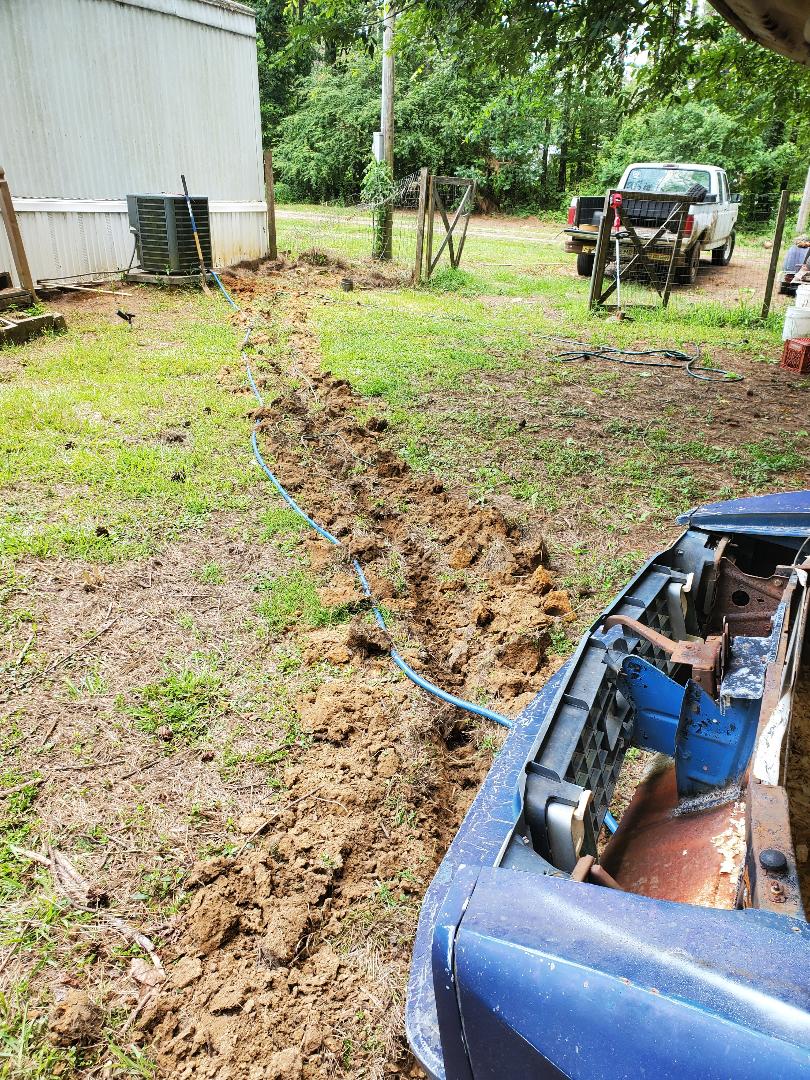
Trench dug out for pipe and cord
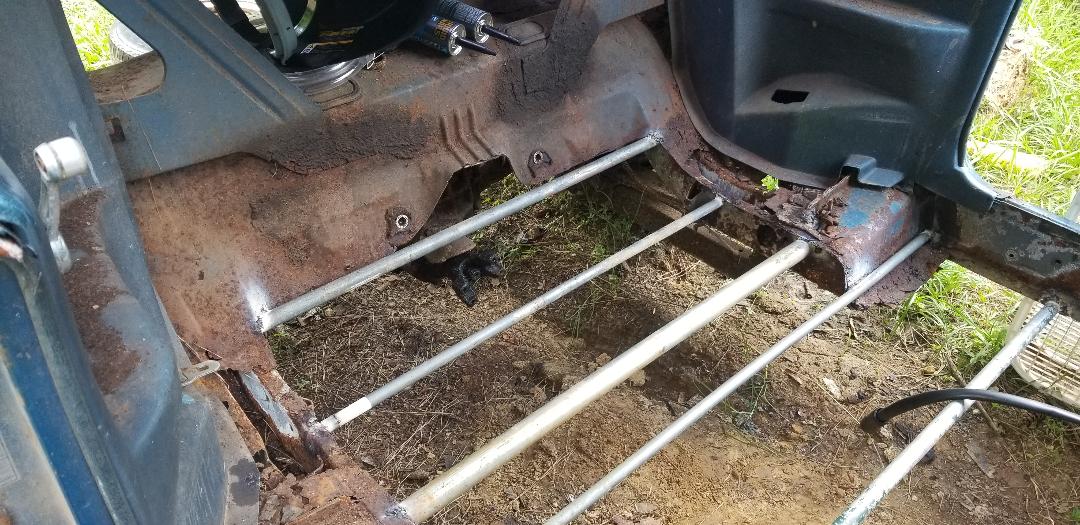
I had to pull the section of skirting rom the house to access the water line where the spigot is at. I had to cut the spigot off so I can install a tee in the line. After installing the tee I put a length of pipe in going straight down into the trench where a 90 degree elbow was installed and another length of PVC glued in place. From there I put a 45 degree elbow on and started my main pipe run to the car. I needed three 10ft sections of 1/2" PVC pipe to get to the last section of trench at the car. Another 45 degree elbow was installed and a final length of pipe put in with a 90 degree. A short piece of pipe was put in and a few fittings used to couple the spigot to the end of the 1/2" pipe. With the pipe and spigot in I went ahead and moved on to the extension cord.
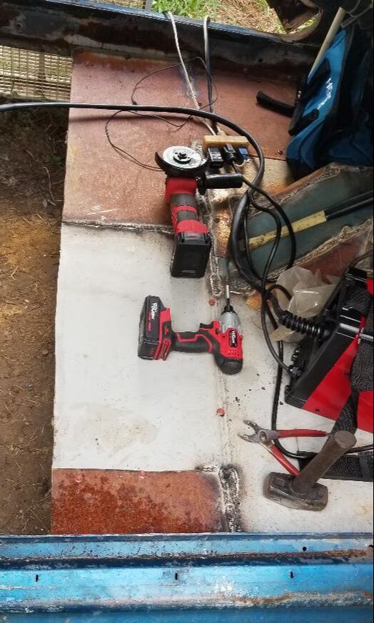
I grabbed an older cord I had that was 50 ft long and plugged it up to the external power box that I put in for the power run to the dog yard. I ran the cord along the other cord to the ground then routed the cord into the trench. Once in the trench I was able to run the cord and kick dirt into the trench as the cord was dropped. I killed two birds with one stone getting the cord in and the trench filled in. This of course didn't take long but I did come up short on the cord and had to grab another old and short extension cord to plug up to the 50 ft cord. I wrapped the plugs in electrical tape to help keep things sealed prior to burying the cord and the plugs. Once at the spigot I was able to finish filling in the trench and route the cord to the underside of the car.
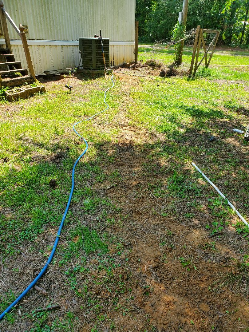
Trench covered up with dirt after laying pipe and power cord
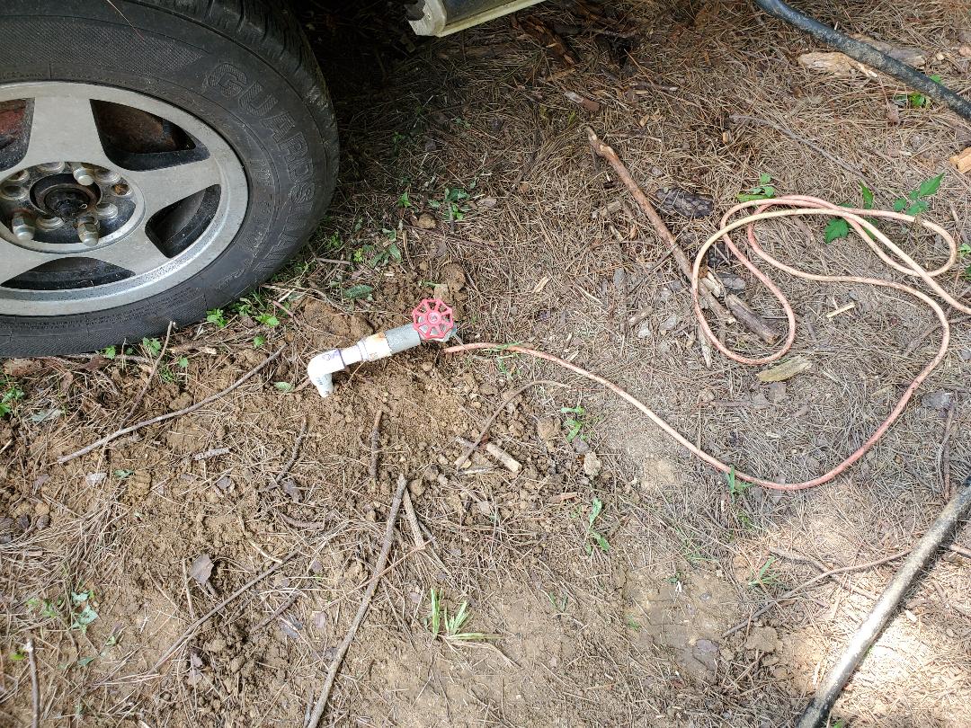
Spigot and power cord next to car after filling in trench with dirt
I had a short length of hose that was on an old automatic watering dish that was in the chicken yard that I pressed into service for the Mustang Chicken Coupe. Once hooked up I fired up the water once again and bled the air from the lines and had water online for the baby chickens but this time through PVC pipe instead of a hose.
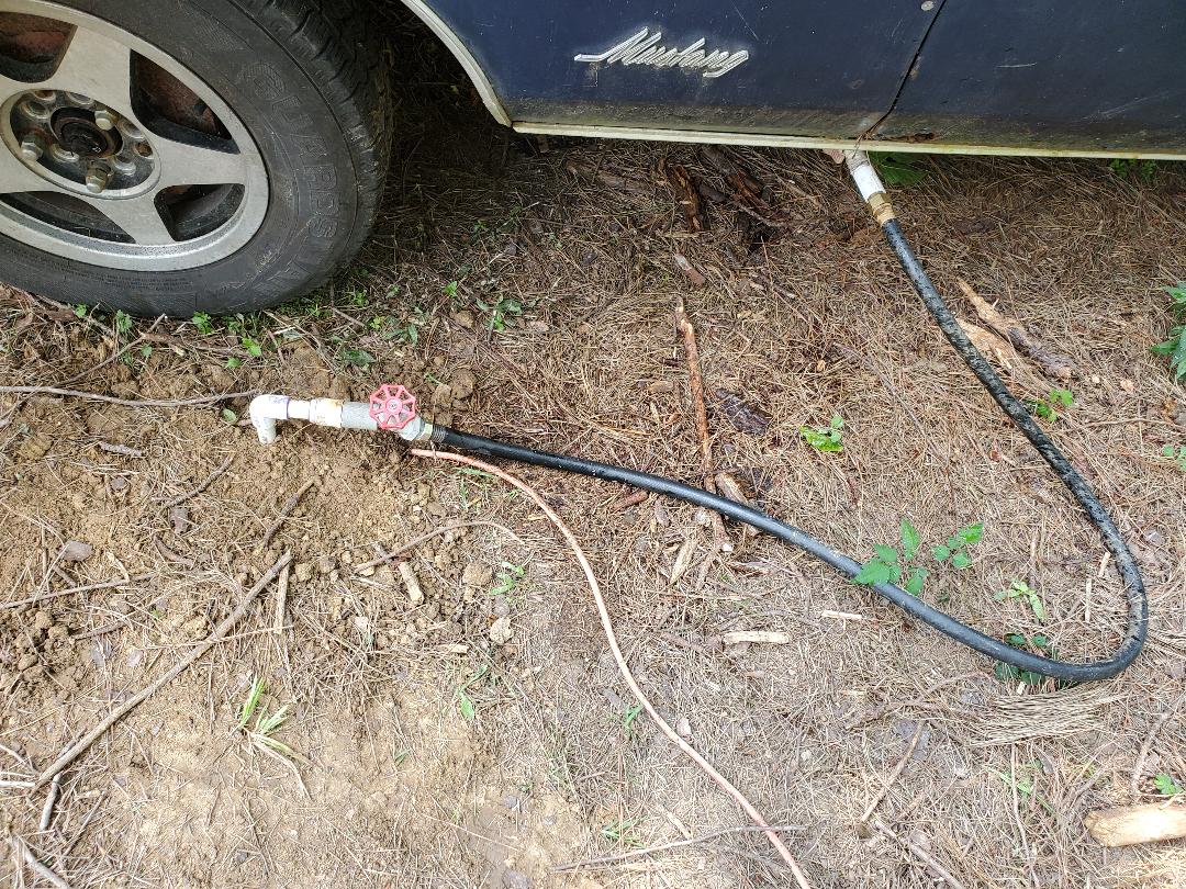
Spigot with short hose hooked up to Mustang Chicken Coupe, serving it with water.
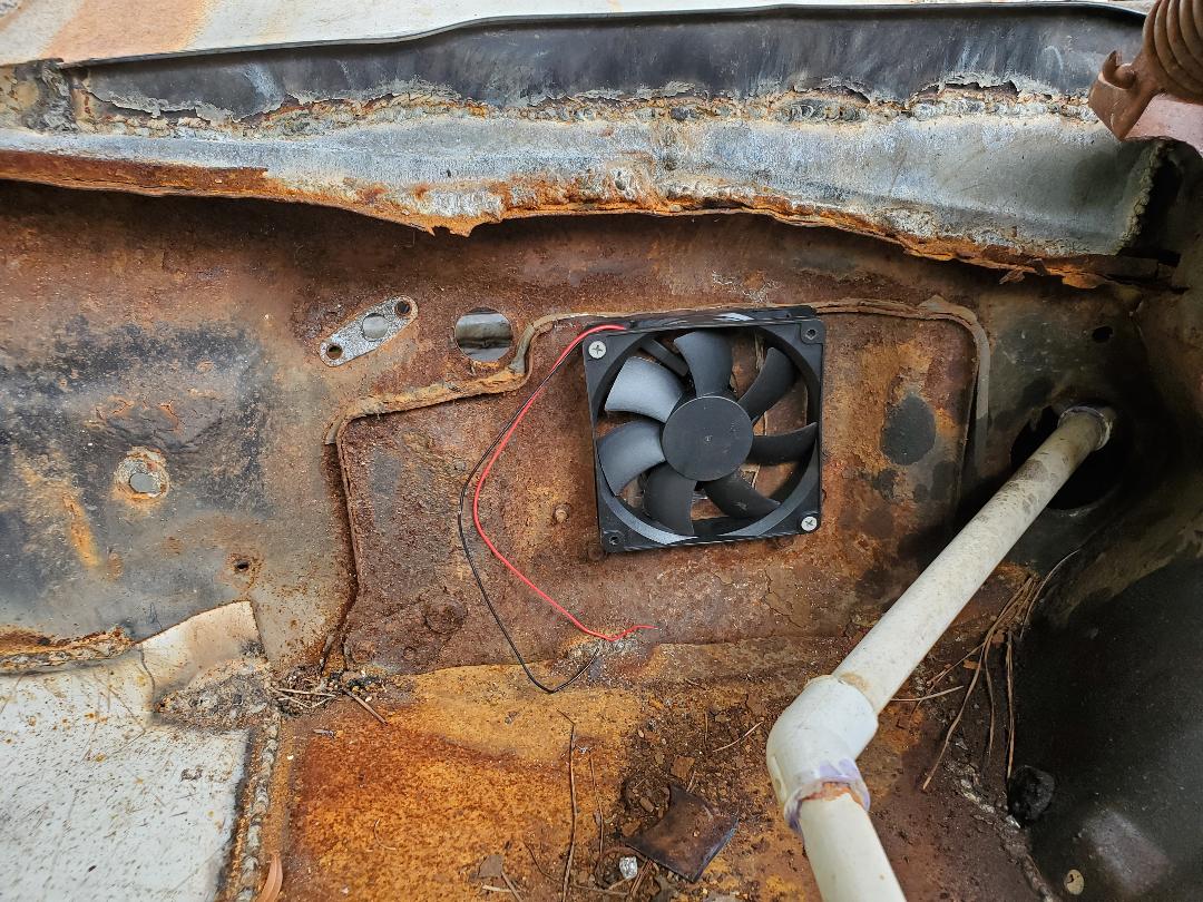
The next thing was the repair of the power cord that got pulled apart when I moved the car into the chicken yard. I decided to just splice the plug and cable back to the other end of the cable. This was pretty easy, just soldering the wires together and taping things up real good then securing the cable with wire ties to the water line going down to the outside of the car. This way I can just plug up to the cord that's next to the spigot. With that the next order of business was getting the fan in the brooder section. I had to find a 12v power supply for the fan, which luckily I had in m stash of miscellaneous electronic crap. I ended up having to plug the unit into the outlet in the cab area due to the idea that the outlet in the brooder is a little low for the heater I had and until I can find a heater that will actually fit the bottom outlet AND the power supply, I put it in the cab area. For all intents I won't need a heater in the cab area anyway, since its for adult birds and they really don't need heat like the baby birds in the brooder.
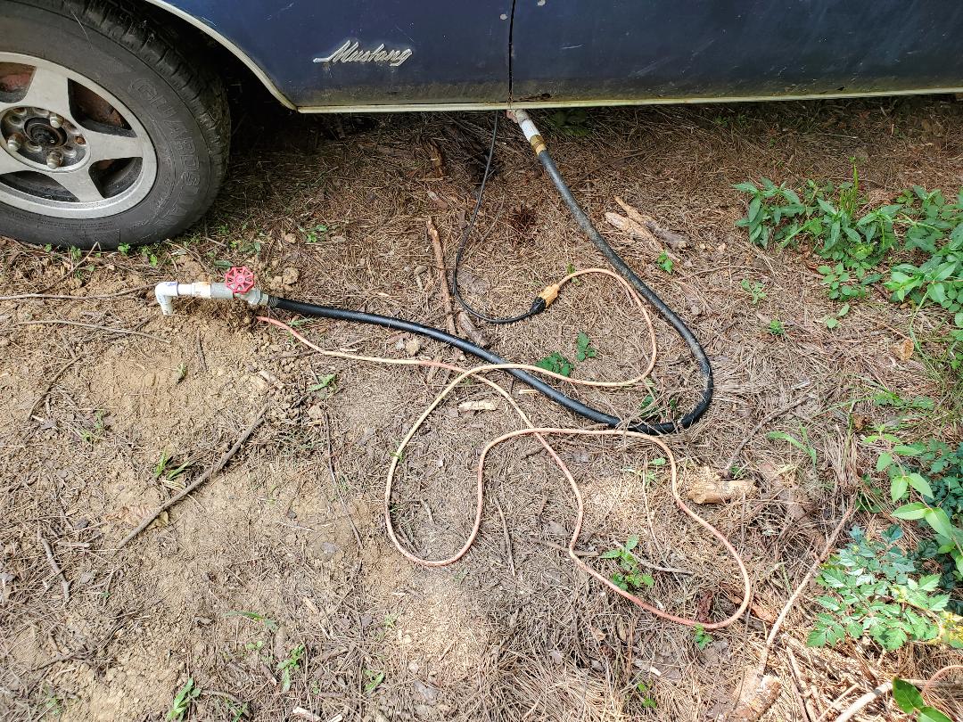
Power plug from car routed under floor to the outside and plugged up to power cable coming from trench.
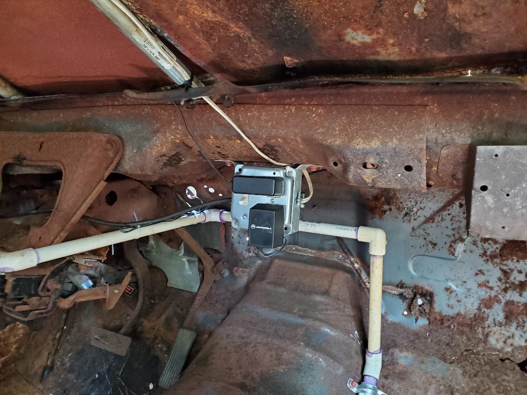
Fan power supplies plugged up to cab outlet. Note power cable wire tied to water line at center left.
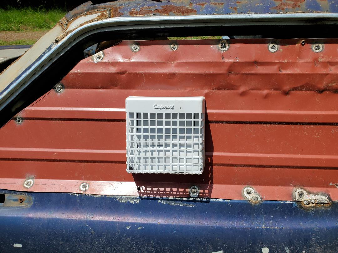
Another thing I had to address on the brooder fan was the fact that there was no screen or cover to protect the fan from foreign objects, or in this case, protect birds from getting decapitated by sticking their dumb adolescent beaks into the moving blades. I had to look around as I didn't have anything that was just perfectly ready to be attached to the face of the fan. While looking around the scrap/auto parts pile in the back by the dog yard I spotted something that just caught my eye immediately. On the dash from the 73 Mustang there was a screen type cover for the speaker that was a piece of sheet metal with holes in it to allow sound to come out. It had four tabs on it and the shape of the cover made it perfect for the job I had for it. I had to bend a couple of the mounting tabs to make the panel fit straight in front of the fan while not being directly against the fan. I used the impact driver and some self tapping screws to secure the two tabs at the "top" and one of the bottom tabs that actually made contact with the firewall. After securing the panel, I marveled at how perfect this setup actually was. The baby birds are now safe from the meat grinder.
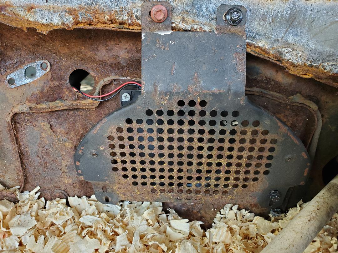
Speaker cover mounted in place, note top tabs screwed down and bottom right tab screwed down. Note fan behind panel, wires coming up from left top side.
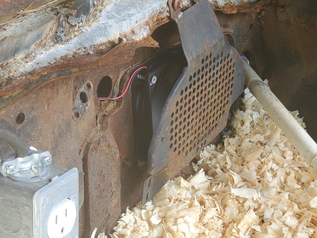
Side shot of fan cover in place, showing fan, which is currently running in the pic.
The next thing was a ramp for the nesting area. This was pretty easy. I had a 2x8 board that I pulled up from the fence line when I was digging the trench from the power pole that was still pretty intact. I ended up cutting a short length of this board and using a bracket that's used for attaching boards together in building frame construction, was able to secure the ramp to the metal going into the trunk area. Good old self tapping screws and some wood screws made quick work of this little job.
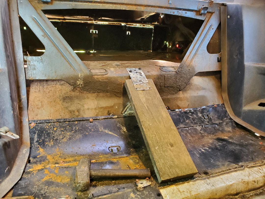
2x8 ramp with bracket securing it to metal interior panel leading into trunk/nesting area.
Now for a roosting post. After some thought this ended up being another simple undertaking as the interior panels are still in place in the car and they have what amounts to armrests made into these panels. This made things pretty easy as all I had to do was cut a piece of 1/2" conduit and use a couple of conduit straps with some screws to hold the pipe to the armrests on either side in the "backseat" of the cab. With this the roosting post was all done.
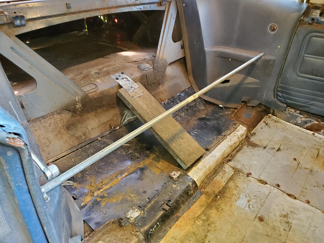
Conduit roosting post in car, note conduit straps holding pipe to armrests on interior panels in backseat area.
With all this done we went ahead and filled the cab and trunk areas with mulch/shavings to prep the rest of the coop for the adult chickens. Our plan is to move some of the birds into the cab area at night when the birds are more docile. The last thing I need to do is make some kind of cover that I can drape over the passenger window so when it rains it'll keep blowing rains from filling the cab with water and ruining the mulch.
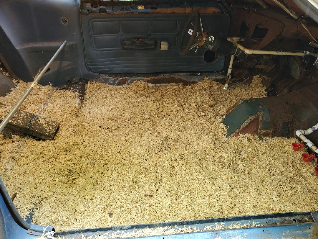
Mulch spread out in cab area, made ready for the birds.
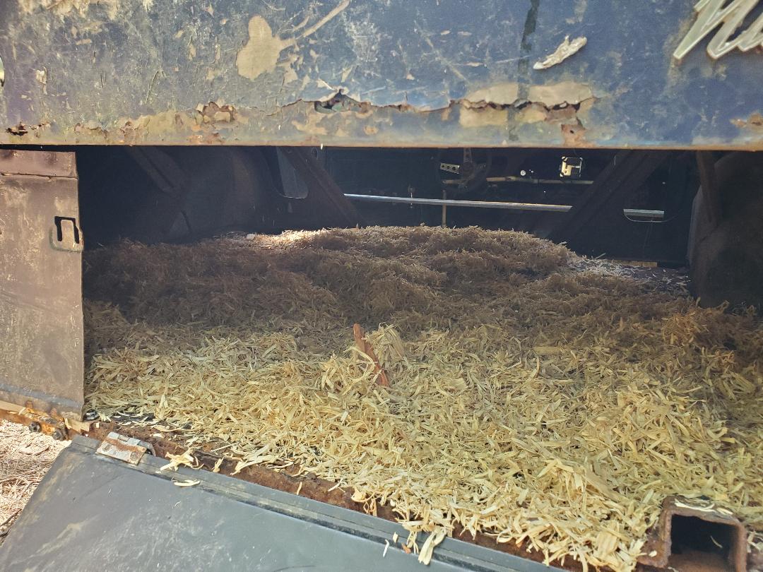
Nesting area filled with mulch, ready for action.
