THE LAWN MOWER CARBURETOR POWERED CAR VERSION 1
FEATURING THE RUSTANG
We're going to try something new here in the world of improvisation. While I'm not the first one to try this idea, it is an idea that was intriguing enough that I just had to try it out. This idea is running a car off of a lawn mower carburetor. Again, I'm not the first one to try this idea, a couple other Youtubers tried this idea with decent success, with the first Youtuber, Thunderhead289, successfully running a Ford 302 V8 off a lawn mower carb and with some little tweaks and minor mods, managed to achieve over 40 mpg with the rig. The other guy ran a Saturn 4 cyl powerplant and achieved high 30's, even though he didn't have the extra mods the Ford had. I'm not going to necessarily go the route Thunderhead did with an electronically controlled air solenoid to maintain a proper A/F ratio, but I do have some ideas to try out that will achieve the same concept. The first thing is actually setting up this rig and picking a proper vehicle for the project.
The vehicle that I chose was the Rustang, the 69 Mustang fastback/Mach 1 variant that is currently powered by a 200ci 6 cylinder engine with a 1bbl carburetor. I figured this car would be a decent compromise, not a large V8, but not one of the 4 cyl vehicles that are currently being used as daily drivers which are also electronically controlled and can give varied results. With the car picked, I then looked up carburetors. I chose a unit that fits Kohler 16 hp lawn tractor engines and doesn't have any kind of extra components, just a manual choke and throttle. With the carb in hand, the next move was to figure out how to couple this carb to the 6 cyl's intake carb base.
To do this, I took some scrap metal, a couple pieces of rigid sheet metal and a 90 degree metal tube and started off by making paper templates of the base for the lawn mower carb and the 1 bbl carb base on the intake. With these templates I traced outlines on the sheet metal, cut these out, along with bolt holes, then welded the two pieces to the ends of the 90 degree elbow tube. With the upper intake plenum done, I made a gasket from gasket paper stock and bolted the carb to the port on the plenum. Next I made another gasket for the intake manifold side.
Another thing I did was source a fuel pressure regulator for our carb because of the idea that the little lawn mower carb will quickly flood out under the pressure of the mechanical fuel pump on the engine. The pressure regulator I found was a low pressure unit that goes between 1 and 5 psi. This should be sufficient enough to provide fuel to the little carb without blowing its seals. The last thing that was done was make an air cleaner for the carb. Since I didn't have a stock air cleaner box, I made one from scrap. I took a soup can and traced another template of the outside port of the carburetor and used this to trace out and cut a hole on the soup can, along with bolt holes. I bolted the can to the carburetor and then zip tied the regulator to the soup can.
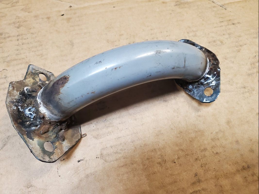
The upper intake plenum welded together with the sheet metal bases to the 90 degree elbow tube. The welds are crude but effective.
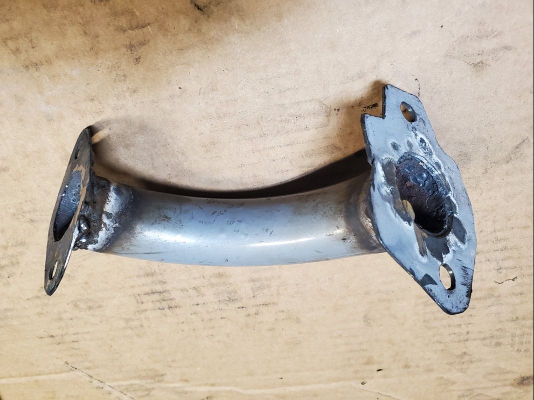
An angle to the upper plenum showing the inside of the elbow and the insides of the sheet metal bases after welding everything together. All slag has been ground down smooth.
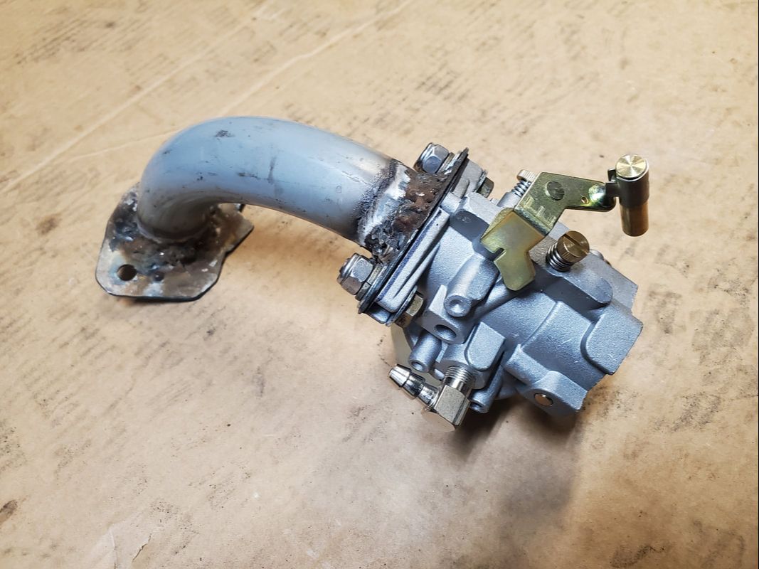
Carburetor bolted to the upper intake plenum, note the popcorn welds that attach the sheet metal bases to the 90 degree elbow tube.
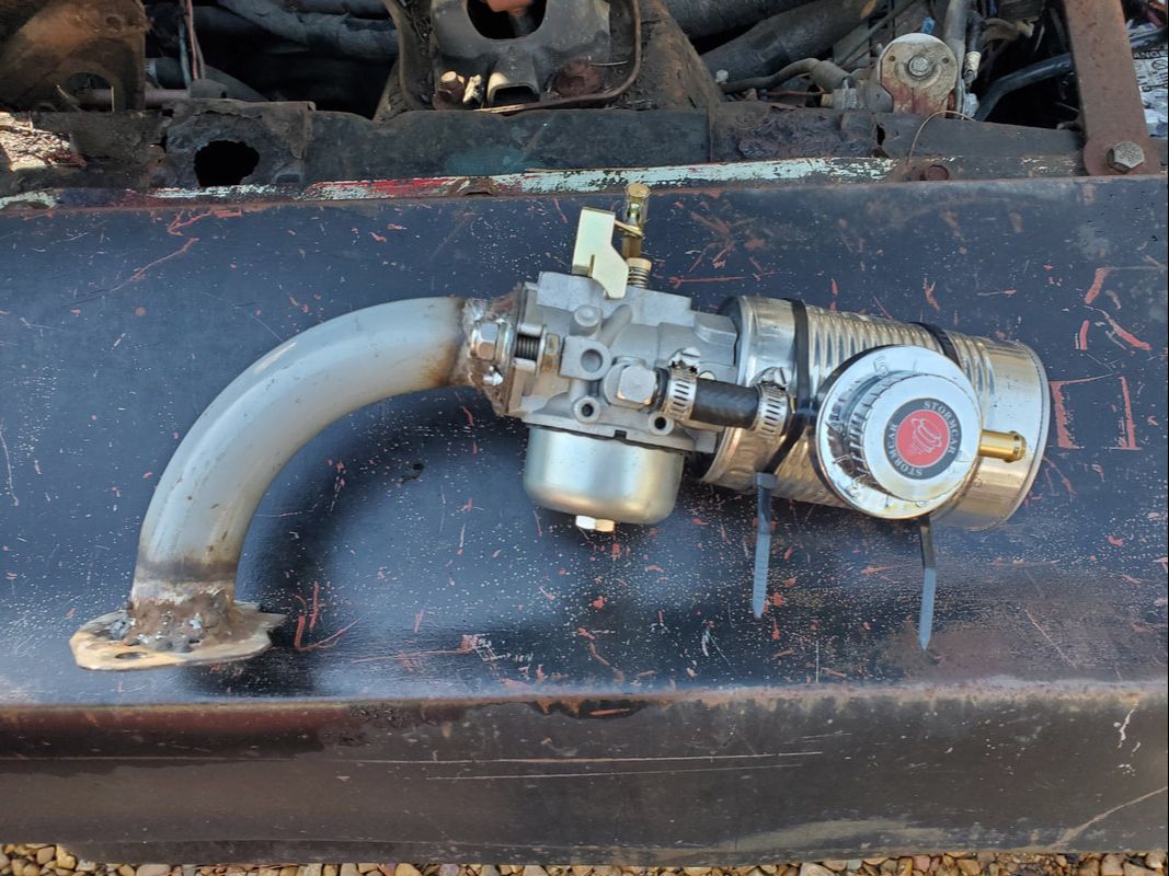
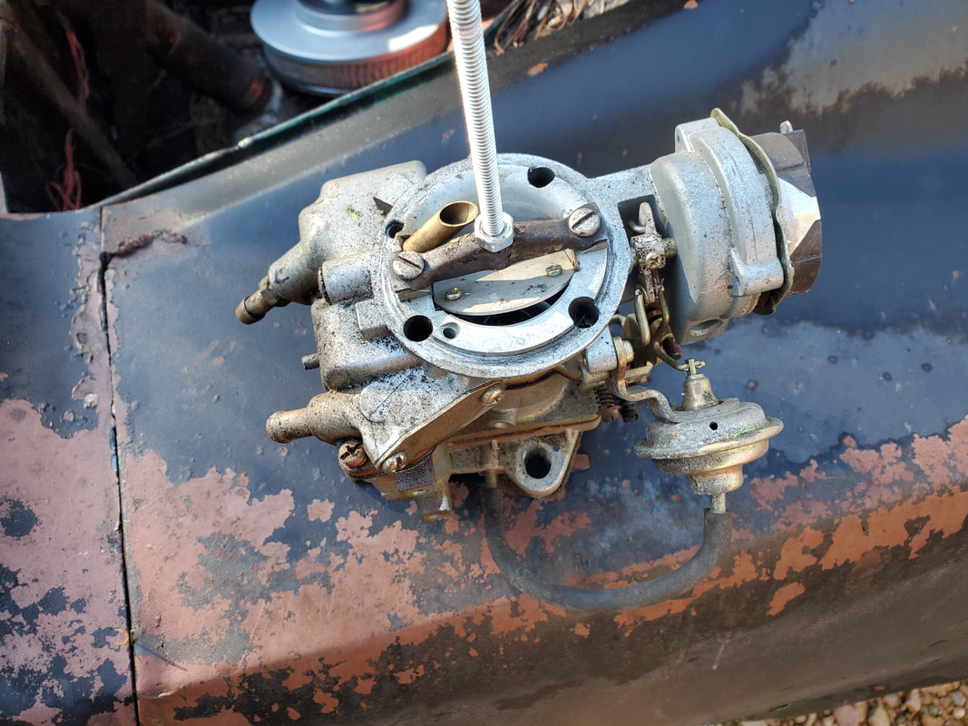
Carburetor with regulator attached and zip tied to air cleaner soup can.
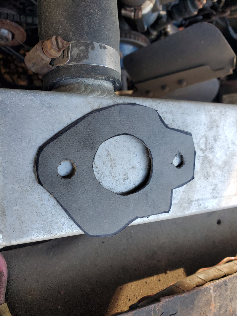
The base gasket cut from paper stock to mount the upper plenum with the lawn mower carb to the intake manifold on the engine.
With our new fuel system assembled, the next thing was to prep the powerplant for it. The 1bbl carb was removed and set aside, the throttle cable was disconnected from the bracket, and the base gasket was slopped up with a thick bead of gasket maker. Since the base plates weren't perfectly smooth and straight, the extra gasket maker would help in sealing the base. At first I bolted the assembly down with the soup can air cleaner facing the front. This would've made it easier to replace the filter element but it presented several other problems. I determined that the convenience of replacing the air cleaner material easily was not worth having to make several other changes to accommodate the other hookups to the carb. I turned the assembly around with the soup can facing the firewall. There's a few inches between the soup can and firewall so I may still be able to remove the filter material easily, who knows. But with this configuration, I can make all the hookups a lot easier. I had to use a spacer nut between the top of the base plate and the throttle cable bracket since we don't have the thick carburetor base that was present on the 1bbl carb. With the rig bolted down, I moved on to the regulator. I just had to remove the short piece of hose on the output side of the fuel filter and replace it with a piece of hose that was around 2x the length of the old hose. This hose coupled the car's fuel filter to the nipple on the regulator. With that done, I moved to the throttle cable.
To achieve this, I had to take a piece of angle iron from my scrap pile and drill some holes in the ends. On one end I bolted the angle iron to the throttle cable bracket, using two nuts/bolts to make the angle iron sturdy against the bracket. On the other end I bolted the throttle cable mount to the angle iron. On the lawn mower carb I took the piece on the throttle linkage that snapped on the little ball tip and installed it on the throttle cable, allowing me to directly snap the cable to the linkage on the lawn mower carb. With that done, I was ready to attempt a start up.
To make things easier, I used a remote starter switch. I hooked this up and attempted a startup. After a brief cranking, the pump pushed enough fuel into the carb to allow the engine to start up. The choke that I manually closed was quickly opened to about halfway, making the engine smooth out some. Trying to open the choke all the way made the engine run a little worse. The sweet spot was around 3/4 open choke. I tweaked the A/F screw and the pressure regulator as well. In the very beginning, fuel leaked from the soup can as the float bowl on the carb was flooding out. It didn't take long after playing around with the carb before the needle valve set itself and the leakage stopped. The engine responded pretty good and ran fairly smooth, but I knew there was some room for improvement. Since there was no vacuum advance on the distributor, this would affect the performance. I did a light attempt to move the car and it was somewhat successful, but with the vac advance not where it needed to be, along with the choke being wide open, the engine stalled when I decelerated. I did another little test where I plugged the vacuum advance to a vacuum nipple on the engine's intake manifold plenum. With the vac advance in place, the engine's throttle response was quick and smooth. Another thing I noticed was some moisture around the base of the upper plenum where it bolted to the engine's intake base. I'm not a 100% sure if the engine was running too rich, or what would constitute a rich condition, since the air intake is for all intents, choked, compared to the engine's vacuum potential, despite the otherwise small volume of fuel. I'm not 100% sure if the carb is still flooding out somewhat under the pressure of the engine's mechanical fuel pump. These are things that will have to be further investigated in the experiment.
When I pulled the plug off the vacuum nipple to plug up the vacuum advance, the engine did rev up and run a little better, which brings me back to the things that Thunderhead289 was dealing with his experiment. Because of the restrictive air intake compared to the engine's vacuum, the engine will run in a rich condition, even without the actual volume of fuel that should create a rich condition. What this means is creating a controlled vacuum leak will aid me in making the engine run better. Thunderhead did this with an electronically controlled idle air solenoid working in unison with an O2 sensor. Of course, I won't be doing this as I don't have the hardware to duplicate this. My plan is to look at a vacuum controlled vacuum leak, if this makes sense. I'll probably tap another nipple on the upper plenum, after the carb, that will feed a vacuum diaphragm that can work a valve that opens up air to another nipple that will allow air to flow into the intake. Maybe with some tweaking I can get things dialed in enough to where the engine's vacuum will control the admission of air properly enough to run the engine smoother. An A/F meter with O2 sensor added will allow me to monitor the performance as well.
The 1bbl carburetor removed from the engine to be replaced by our lawn mower carb assembly.
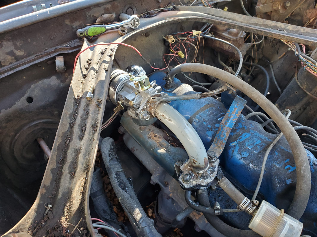
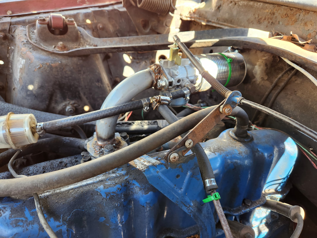
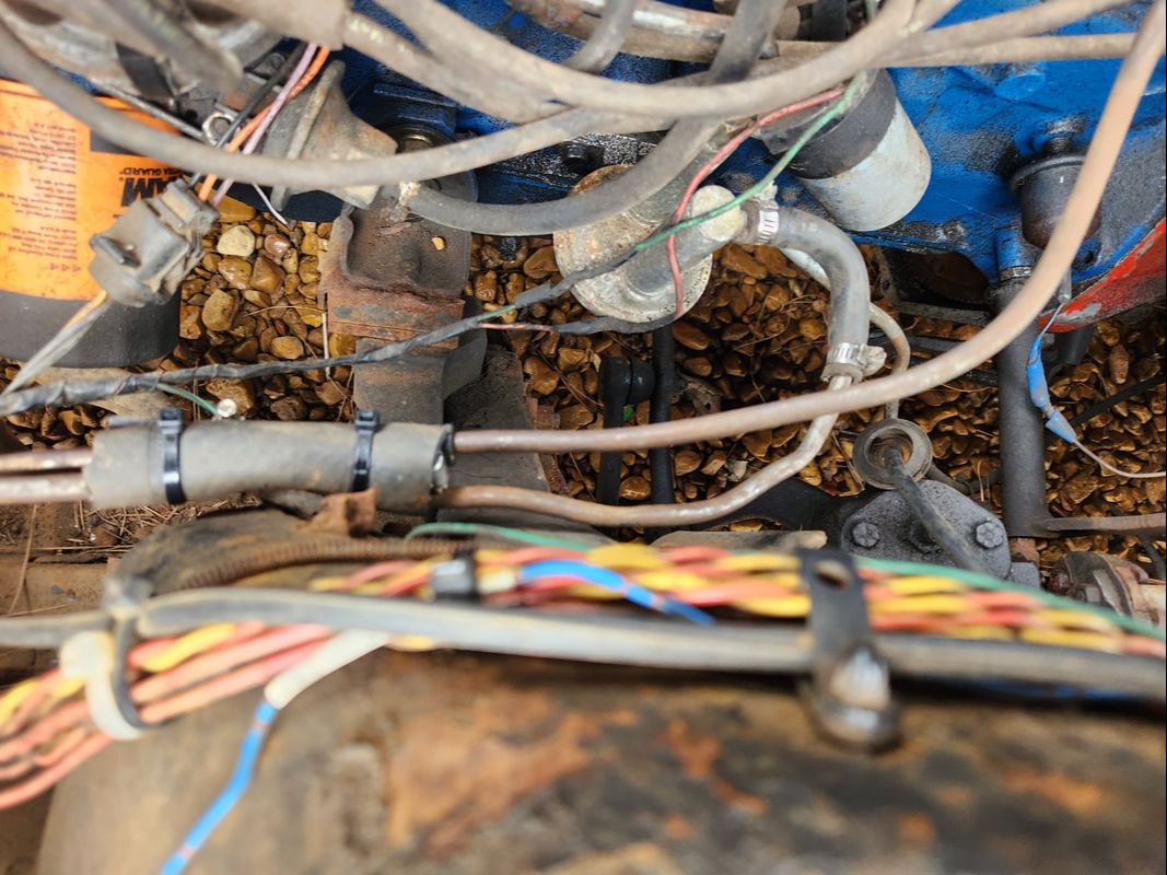
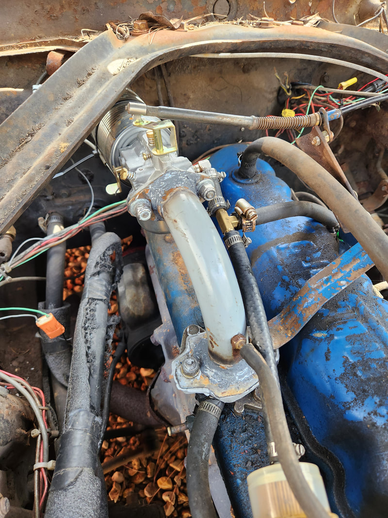
The upper intake plenum and carb combo bolted in place to the carb base on the engine.
The extra length hose added between the fuel filter and the input nipple on the pressure regulator.
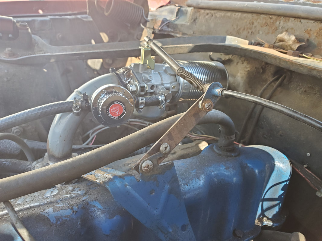
A closeup of the angle iron piece that was drilled out and bolted up to the throttle cable bracket at an angle. The throttle cable is bolted to the other end of the angle iron piece. This put the throttle cable at the right position to put it straight in line with the linkage on the lawn mower carb.
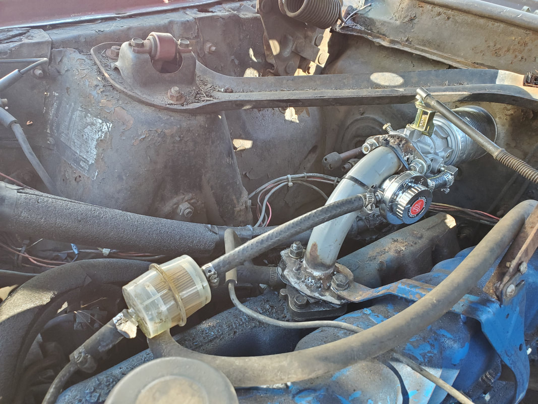
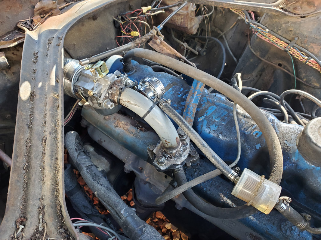
Another angle to the intake plenum and carb/regulator assembly as it is hooked up to the 6 cyl engine.
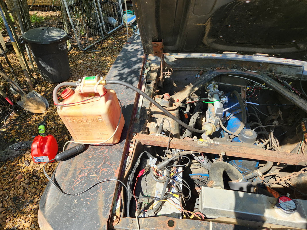
With the initial testing taken care of on the mower carb, it's time to move into the second phase of the project. There's a few things I wanted to set up on here, but the biggest thing that I want to do is set up a temporary fuel system that would allow me to test the system for the sake of checking what my MPG numbers would be with the system. One of the first things I installed was a regular choke cable, routed to the cab and under the dash to allow me to operate the choke on the mower carb. Zip ties allowed me to secure the cable just right so it could cycle the choke lever. The next thing I did was start setting up the fuel system. This consisted of a gallon fuel can that I placed in a spot between the grille and core support. I drilled two holes in the top to accommodate metal tubing, sourced from my scrap pile. The tubes were bent to allow one tube to reach down to the bottom of the can and bend around the core support and straight back towards the fuel pump. The other metal tube only went into the hole an inch. This would be the return line so it wouldn't need to go to the bottom of the can. This tube also snaked around the core support and to the engine. I had to add more tubing and short pieces of rubber hose to couple the pieces of metal tube together. On the fuel pump, the metal line was disconnected and the short rubber hose on the fuel pump was connected to the metal tube and on the return side I removed the pressure regulator and replaced it with a brass tee. The stem of the tee was connected with rubber hose to the end of the metal tube, which snakes back to the fuel can. The fuel pump will essentially pump most of its pressure in a circle back to the fuel can and around again, bleeding off a little to fill the mower carb, hopefully keeping the pressure down to a reasonable level. The next thing installed was an air/fuel gauge and an O2 sensor bung in the exhaust pipe. The gauge was installed under the dash and tapped into the existing electrical wiring, with the sensor line routed around to the other side of the engine where the exhaust pipe is at. A large hole was drilled with a step bit to accommodate the O2 sensor bung. After grinding the metal down, I welded the bung in place. I will be trying to source a single wire O2 sensor from the junkyard, but if this is unable to be found, a newer style sensor will be used, with the other wires clipped, leaving the sensor line to be hooked up. With all this in place, all that's left is for me to add a small hose nipple, which will have to be tapped into the intake plenum for the mower carb. This will be for the vacuum advance tube on the distributor. Once this is done, I should be ready to fire the engine back up and tune the system and prep it for road tests.
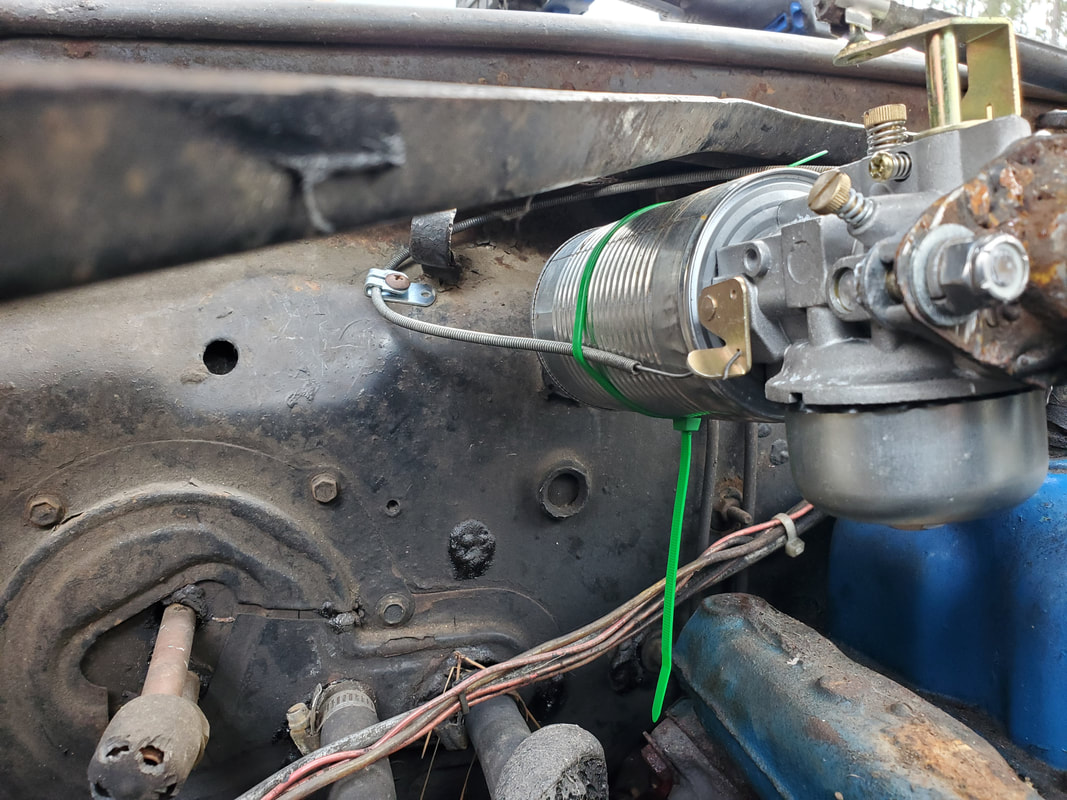
Choke cable end zip tied in place and secured to firewall with a bracket. It's in line straight enough to hook into the choke lever to cycle the lever completely.
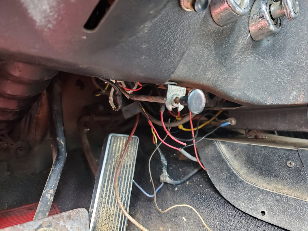
The choke cable knob, anchored under the dash in a spot where it'll be easily reached while not being in the way of my feet.
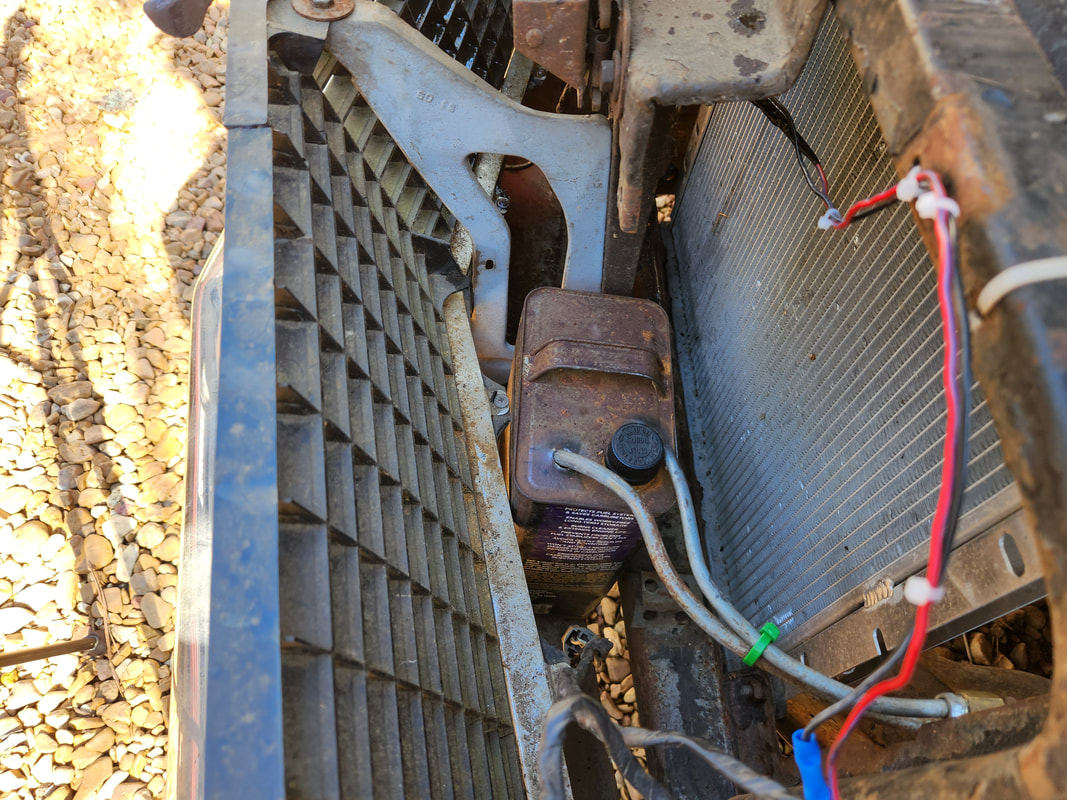
The fuel can situated in its little spot between the grille and radiator. Holes were made in the top of the can to accommodate the metal tubes that will serve as the feed and return lines for the fuel system. The metal tubes are held together with zip ties to keep things neat.
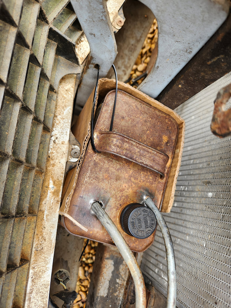
The gallon metal fuel can installed in place. A piece of cardboard is wrapped around the can to keep it insulated from contact with the metal surfaces in this area. Zip ties are used to secure the can at the bottom around the hood latch support member and around the can's handle through the same support member.
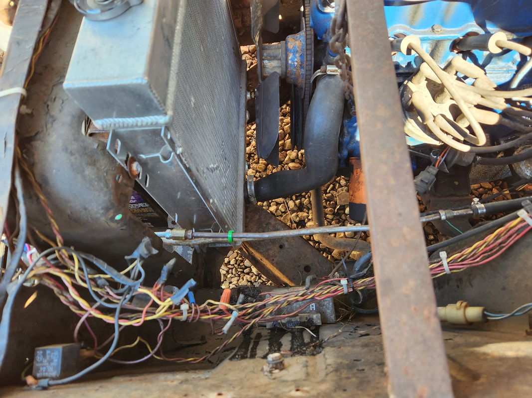
The two metal lines as they bend around the radiator and run straight back to the fuel pump alongside the engine. Zip ties hold the tubes together.
The brass tee installed in place of the pressure regulator with the stem of the tee serving as the return line going back to the fuel can. Hopefully this bypassing of the bulk of the pressurized fuel will keep pressures that are bled off to the mower carb down to low levels.
A piece of heater hose is cut and wrapped around the two metal tubes where they rub against a sharp edge on the shock tower. Zip ties hold the hose in place. Note the rubber hose going from the fuel pump to the metal tube that is drawing from the gallon fuel can.
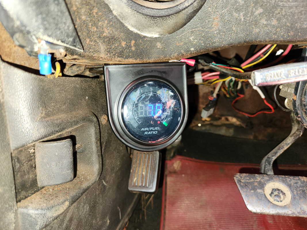
The air/fuel gauge installed on the far left of the under-dash area, where its out of the way of the pedals that are used. The parking brake pedal that's blocked is not used due to the parking brake never having worked on this car.
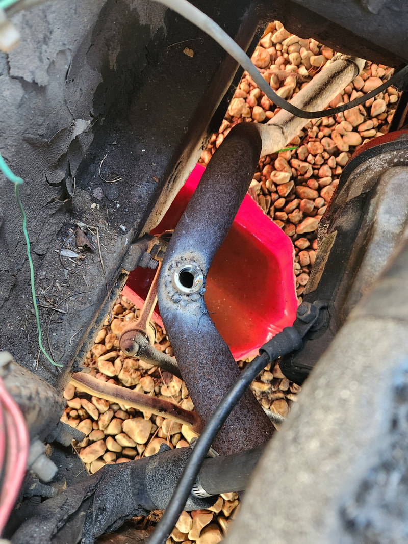
O2 sensor bung welded in place after drilling hole with step bit. Even with the grinding of the rust to bare metal, the flux core welder still ended up giving me the popcorn weld bead that is seen here.
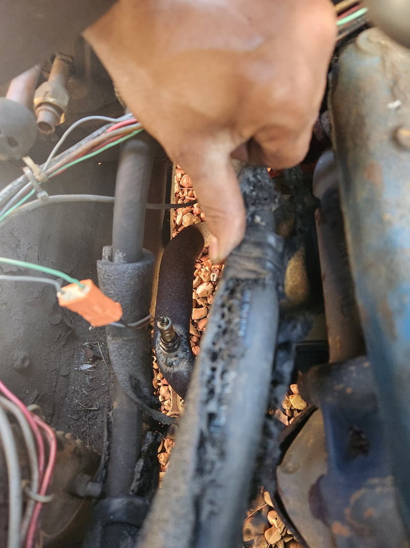
With the O2 sensor bung in place, a trip to the junkyard netted me an O2 sensor. Along with that I installed a hose barb fitting in the intake plenum tube for the mower carb. This barb fitting is for the vacuum advance on the distributor and allows for the other hose barb fitting to be left open to help in leaning out the air/fuel mixture for efficient operation. Upon trying to start the engine, I found my bypass setup with the brass tee and return line really wasn't working. The mechanical fuel pump doesn't pump a high enough pressure to push fuel over to the carb after the return line tee. I would've had to have a fitting on the carb that would allow fuel to hit the carb first then go through the return line. I ended up installing the pressure regulator and omitting the return line setup. Another thing that I did was advance the distributor timing. This was because with the thinner mixture, ignition would have to happen even earlier to ensure that all of the fuel mixture is ignited and putting pressure on the piston after reaching TDC. Now with these things taken care of, I was able to run the engine and further tune things, using the AF gauge to meter how the engine is running. I ended up finding that the engine at idle will have some jumpy AF numbers, so I had to make adjustments based on what appeared to be an average. I got the system to where it would dip as rich as 10:1 and as high as 15:1, with the average floating around 13:1. This was reasonable enough, as I would prefer an AFR closer to rich, since more fuel does help in cooling the cylinders in the engine, minimizing the risk of the flame front burning a hole through any of the pistons. I even managed to do some driveway tests, going up and down the driveway to test for acceleration and engine reaction, which for the most part was "normal'. I did notice that the AFR would go rich during acceleration, which I would assume is normal since I am administering more fuel into the intake, then go super lean after deceleration as the vacuum was still high, drawing more air in, despite the fuel flow slowing down to idle levels. So far so good, so I took a moment to add some camera and phone mounts to get ready for doing the road tests.
O2 sensor installed. This piece is a 4 wire unit with an onboard heater, which isn't used. The wires for the sensor part of the device are wired to a two piece plug assembly that is wired into the gauge in the cab.
The mower carb intake plenum with the hose barb installed for the vacuum advance. Another thing I did to help in making this intake plenum better was coating the weld slag beads with JB weld to ensure the pinholes present between the slag are all filled in, so the intake is fully sealed at these points.
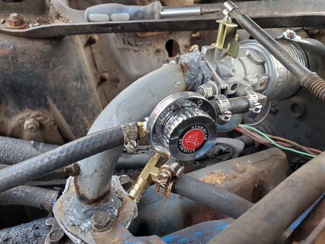
I had to reinstall the low pressure fuel regulator due to the return/bypass setup not allowing fuel pressure to push fuel to the carburetor. Note the brass tee and fuel line still present beneath the intake plenum, prior to later removal.
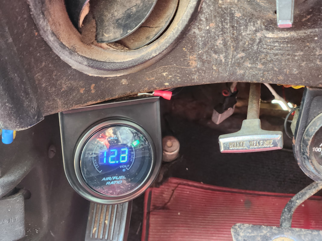
After some tweaking of the carburetor adjustment screws, the average AFR floats between 13 and 12:1, which is satisfactory, better to be a smidgen rich than lean.
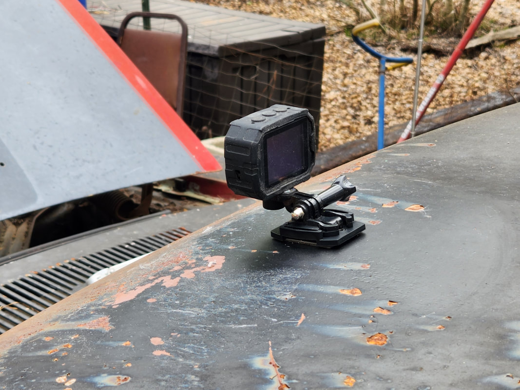
An action camera is mounted with a sticky mount on the roof to get a camera angle from the roof as the car drives down the road.
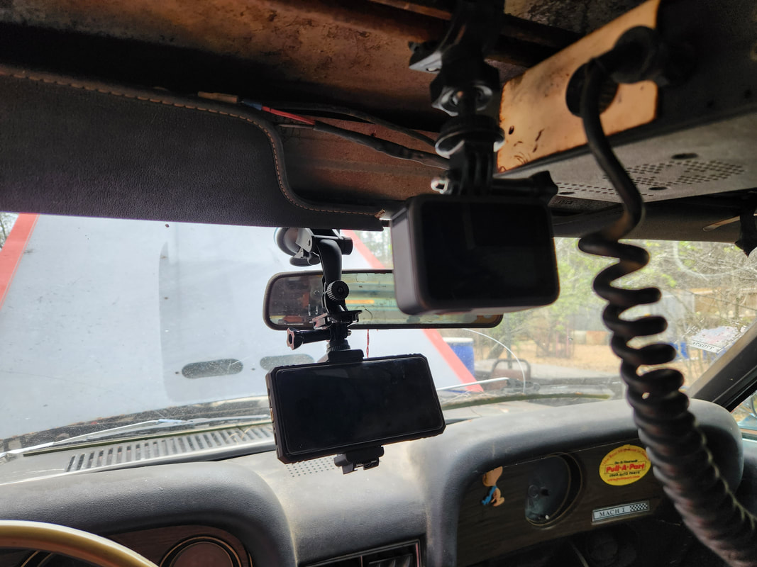
Another action camera is mounted on the post that I installed a while back to hold the CB radio in place. This camera is aiming at a window mount for a phone, which will have the GPS speedometer app working on it. The camera will record the speedo numbers in real time while watching the car ride down the road from inside the cab.
With the whole bypass idea not working out, I had come up with another idea to measure MPG. I figured that flow meters existed to measure how much liquid flowed through a sensor. This amount of liquid, fuel, that flowed in a certain amount of time compared to the number of miles driven can be translated to a MPG number. I found a complete apparatus that included a sensor with ports that were small enough to fit on a regular automotive fuel system, along with a controller and enough wiring to allow the controller to be placed in the cab of the car. I hooked the sensor up in-line with the other fuel line components, routing the wiring harness through the firewall and over to a point above the steering column. I made a cable that terminated with a 12v plug instead of using the AC adapter that came with the apparatus. After a few attempts to run the engine with the apparatus running, I found that the system was not able to measure the minute amount of fuel flow going to the carburetor. The minimum rate this system needed before it would register was much higher than what is flowing through the fuel system. With that failure, I removed the system and put things back as it was. I did a second attempt at a return line setup, with the fittings placed in a way to allow more fuel to hit the carburetor before going into the return line. Even this version didn't work, the carburetor needs a specific pressure that allows the larger engine to run while delivering the larger flow of fuel that is running through this carburetor when the engine is running. I ended up using my Portable Fuel System as a fuel supply, which kills two birds with one stone. Since it's got an onboard fuel pump, it would be able to push fuel to the engine with an evenness that the mechanical pump couldn't really do. I also relocated the pressure regulator to be right after the PFS's fuel pump. Apparently, the pressure regulator is causing some kind of weird vapor lock choke point where it will drastically slow down the flow of fuel through the unit and to the carburetor. This little problem will need to be addressed if I want to have a chance at running the system with a minimum chance of hiccup.
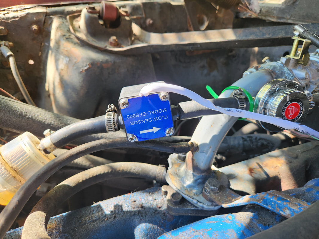
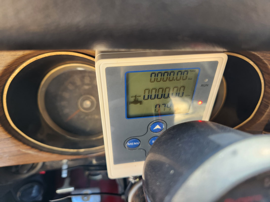
The flow sensor part of the flow meter kit installed on the fuel line. If the fuel flow was enough to spin the internal impeller, it would translate to a signal read on the controller to show the GPM and total gallons flowed.
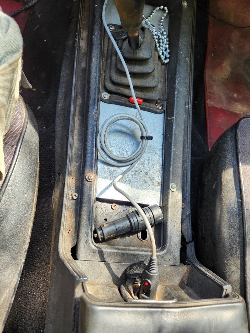
Since the kit came with an AC adapter, I took a similar plug and wired it up to a 12v plug to supply power to the controller.
The controller was mounted just above the steering column, using some exhaust pipe strap, bolted to one of the screws on the gauge cluster panel. The wires are routed neatly from under the dash and around the center console to where the 12v plug is located.
Because it appeared that the fuel system was suffering from vapor lock, where a choke up would occur that would stop the mechanical pump from pushing fuel through to the filter and the carburetor, I tried the Portable Fuel System's electric pump to see if a steady pressure would overcome any vapor lock conditions that are keeping a steady fuel flow to the carburetor. The PFS can also serve as our medium for measuring MPG since its built on a gallon fuel can.
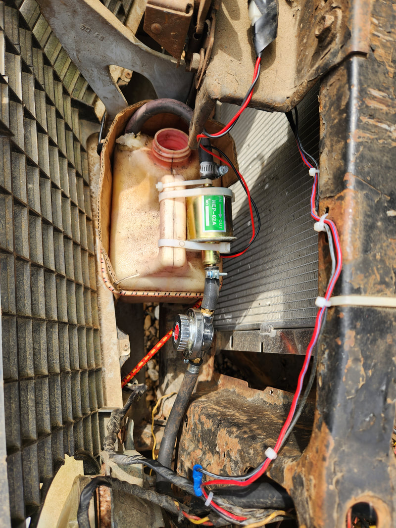
The PFS is reinstalled in the same spot where the old gallon metal can was strapped down. Bungee cords hold the system down. The power wires are routed where they're safely out of the way but able to be connected quickly to the battery. The pressure regulator is connected to the output on the fuel pump, hopefully out of the way of any extreme engine heat that might cause a vapor lock condition. An extra long rubber hose is connected to the regulator and routed around through the core support and over the top of the engine to the fuel filter, which is directly connected to the carburetor. The rubber hose is zip tied to the shock tower brace to hold it up safely away from the fan and ignition system wiring.
