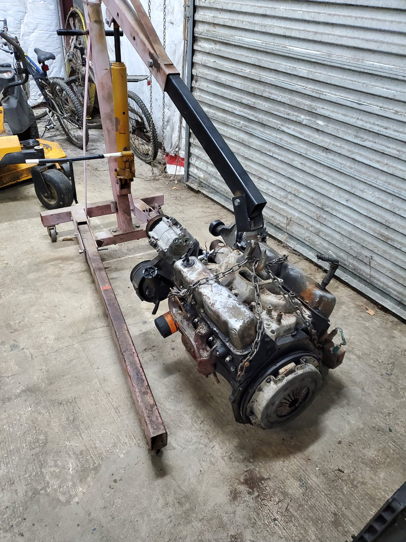
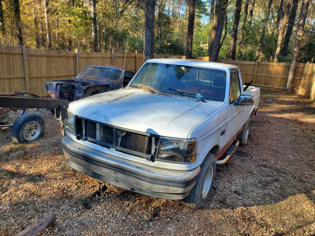
THE FMT (FORD MUSCLE TRUCK)
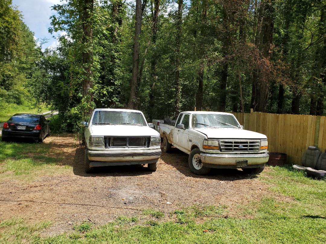
FMT staged next to F250.
One idea that I had for this truck regarding the two fuel tanks is the idea that when I re-do the fuel system, I would actually just go down to one tank, keeping the front fuel tank where the filler port is in front of the rear wheel. I would remove the rear fuel tank and actually install a spare tire winch mechanism that you would typically find on some trucks and SUV's in order to keep the spare tire tucked away under the truck so its not riding along in the bed loosely. This would keep things nice and tidy since this truck to some degree would have a bit of a "show" aura about it being a variant that is more sought after and harder to find.
The other issue with changing things over on this "newer" truck is the transmission. The automatic transmissions in these and similar vehicles are computer controlled, using solenoids instead of hydraulic pressure from a throttle valve (TV) cable or vacuum diaphragm to activate the pistons that work the bands to control the shifting, as in an older transmission. Because the E4OD transmission is computer controlled, it would require a working EFI system to feed back info to the ECU to tell it when to shift the transmission. This is something that won't be present when there's a 4 bbl and mechanical fuel pump in place of the complex EFI system. The only option if I were to keep this transmission would be to buy an external transmission controller (which is typically expensive). Otherwise I would have to install an AOD auto tranny, which is the older version of the E4OD, being controlled by a TV cable. These are the only 4spd OD auto tranny options available in Ford. I'm not going to overcomplicate things by trying to install adapter plates to allow me to use other brand transmissions and all that. So what am I going to do? Well, the only other factory option for this truck is a 5spd manual M5OD transmission.
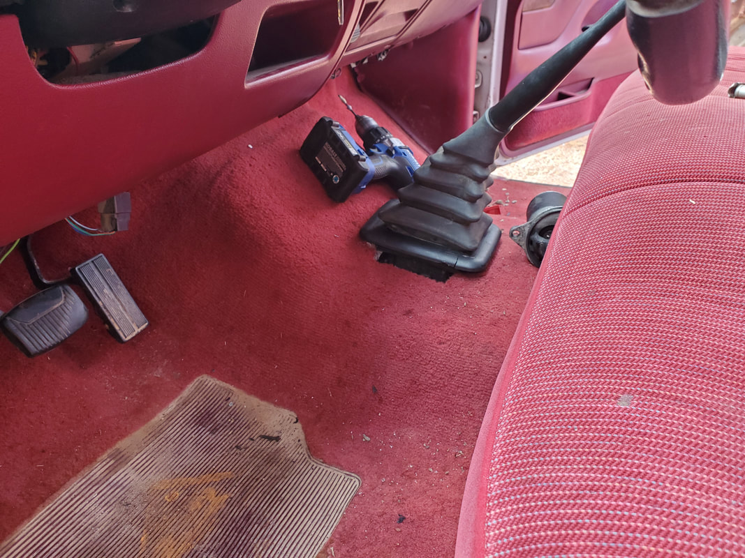
This transmission would bolt right in as it came standard with this truck and would allow me to continue with the build with minimal modification. The crossmember should bolt up, hell maybe even the driveshaft will bolt up or just require a yoke swap out if the splines are different between the auto and manual transmissions. This transmission will bolt right up to the 302 engine and fit right in the transmission well under the truck. Even the shifter location will match up where I won't have to change seats because the shifter is coming up through a different spot in the floor.
The only things I'll have to do in incorporating the 5spd is either cutting a hole or removing a plate (if one's present) for the shifter, install a clutch master cylinder (which a factory spot is present) and change the pedal assembly to incorporate the one with the additional clutch pedal. If I choose I could remove the column shifter or just leave it there as a way of confusing a potential thief. Now while these trucks use a speed sensor in the rear end, I will have to see how that will work as far as its interface with the ECU and whether I'll have to keep the ECU as just a medium for the use of the gauges or if I'll have to go another route.
Now as for the engine, after doing some research I found that the cylinder heads on the older generation 302 V8's and the newer ones with the EFI have the same bolt ups for the accessories, whether the serpentine belt or regular V belts. I will have to utilize the serpentine belt system that was on this truck since the power steering, alternator and AC compressor that hook up are all driven off a serpentine belt. With the compatibility, it will literally be like I just took the stock engine and swapped out intakes to incorporate a 4bbl carburetor intake vs the EFI intake.
Also since hte EFI system used what was called the EEC ignition system, I would have to get rid of that as well and go back to an older style ignition system. Since I'm not going to a points system (even though that would be the epitome of simplicity), I would either have to go to the Duraspark electronic ignition system, or use one of the hybrid HEI systems that incorporate the GM ignition with a distributor that fits a different brand engine. In this case, since Duraspark would require me to wire up an external ignition module and ballast resistor, I'll be going with the hybrid HEI system. This uses the same HEI onboard ignition module and distributor cap with onboard coil that was used on GM/SBC V8's in the 70's but its built into a Ford distributor. This means I'll only have to get a couple of wires to the distributor for functionality and not have extra devices hooked up outside of the unit. These distributors can be had for about the same price as a reman factory replacement Duraspark or EEC dizzy for a Ford V8.
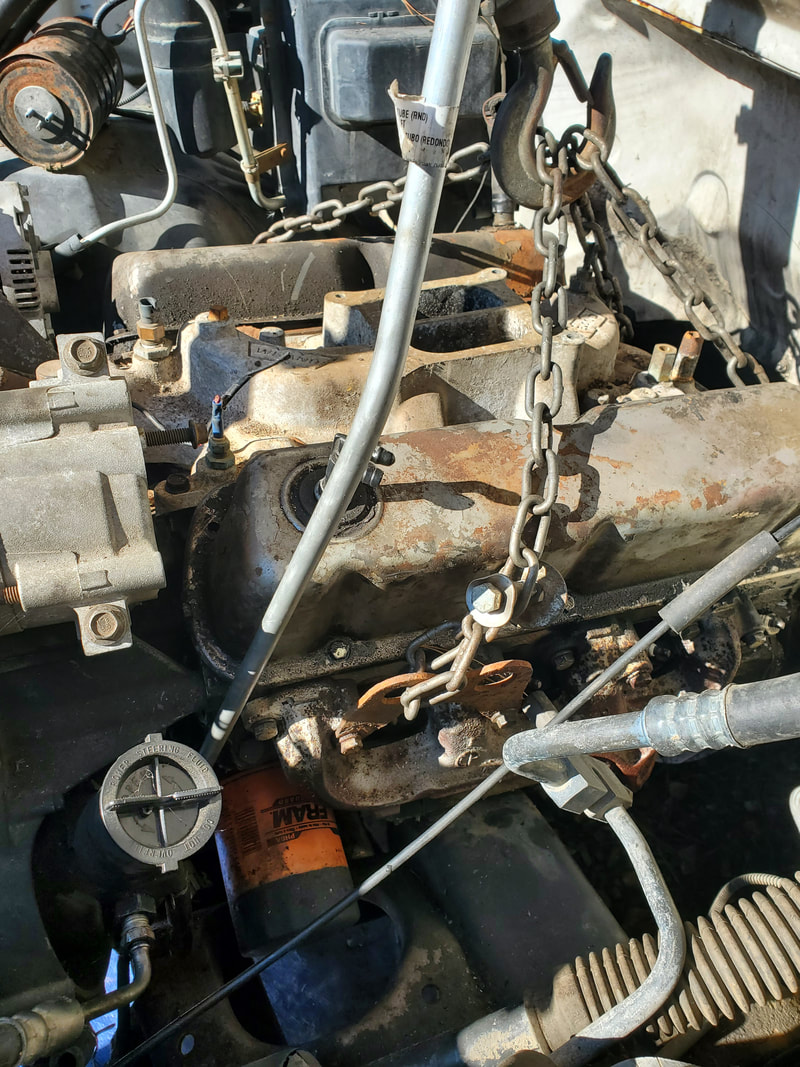
Next on the list here was the removal of the old engine block. Since it was 2/3 disassembled, it wouldn't be a lot of weight to remove so hooking the crane up to hoist it out wouldn't be much of a hassle. All I have to do is remove the bellhousing bolts to separate the tranny from the engine and use the old cylinder head bolts to hook the crane's chains to the engine then lift the unit out. With that old engine on the ground I can remove any salvageable hardware I may need for the new engine and scrap the rest.
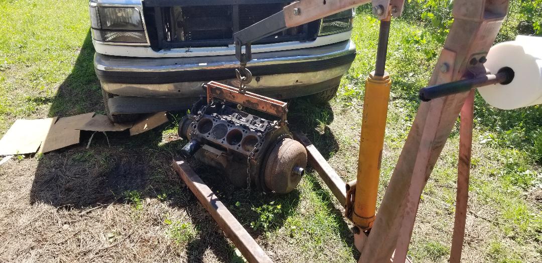
Removing old engine from truck's engine bay.
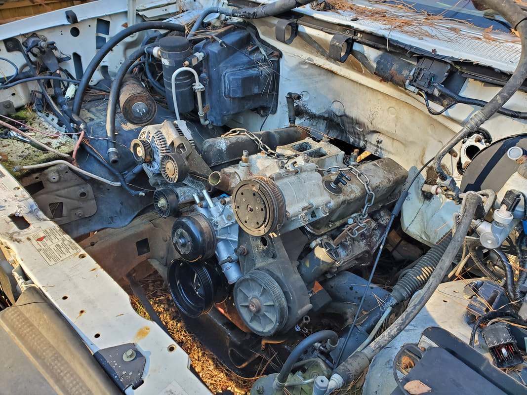
With the old engine out the next thing was cleaning up the engine compartment. This would involve removing anything that is not needed for the older generation hookup. This would include the EFI fuel rails, vacuum lines and other associated hardware, charcoal fuel canister, etc. The ignition wiring and related hardware would have to come out too. So would most of the engine bay wiring harness since this includes the wiring for the fuel injectors and any solenoids and sensors from the old system.
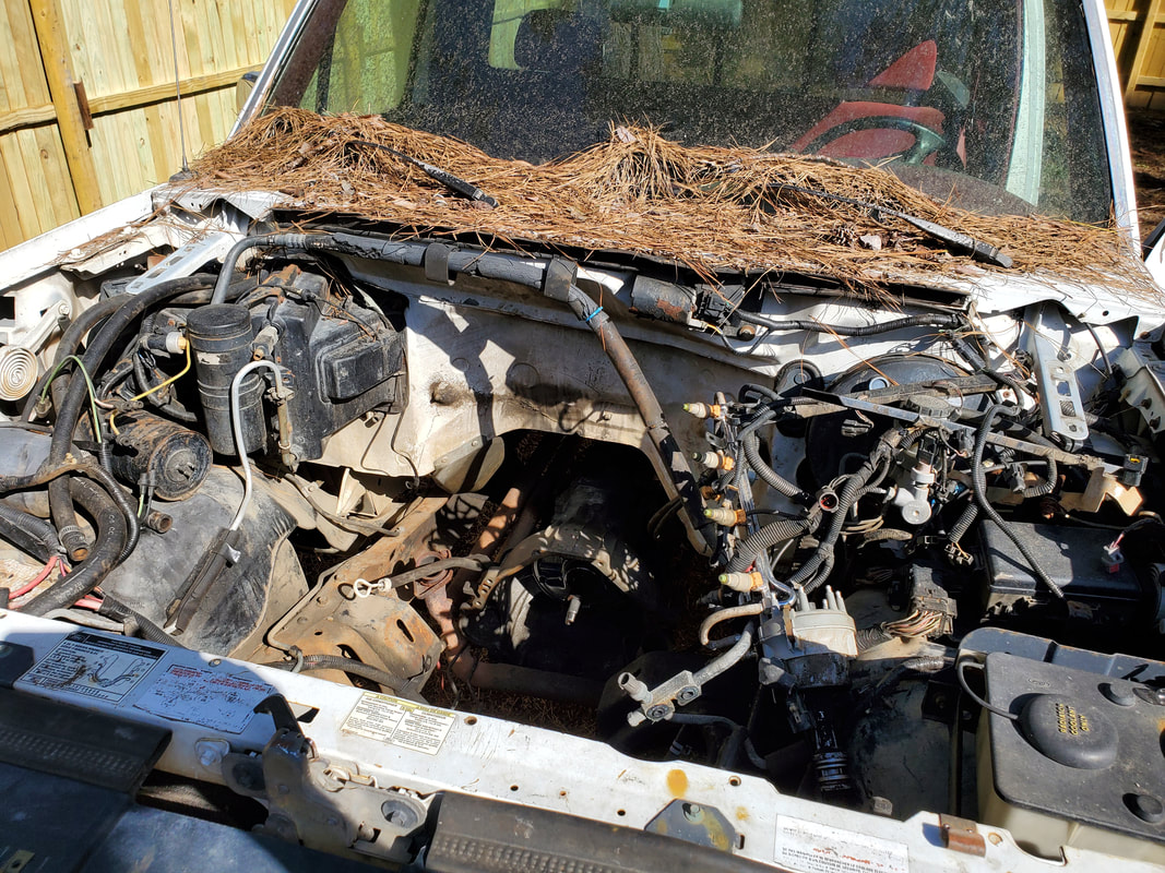
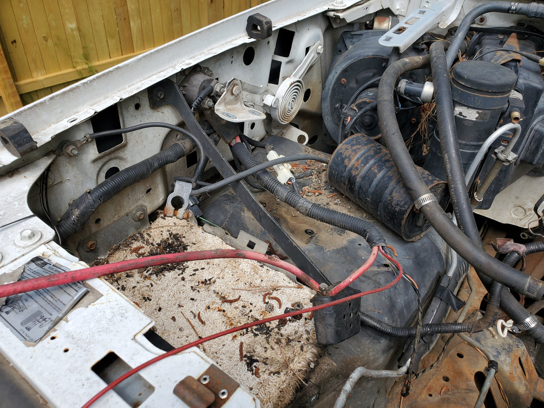
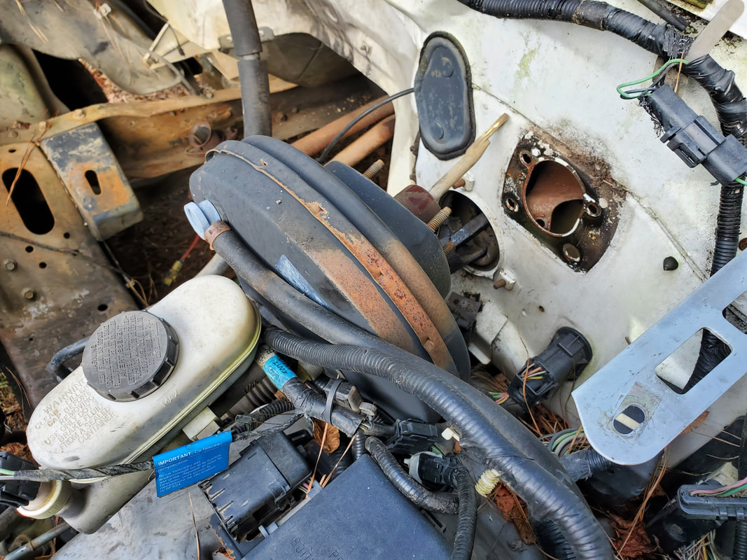
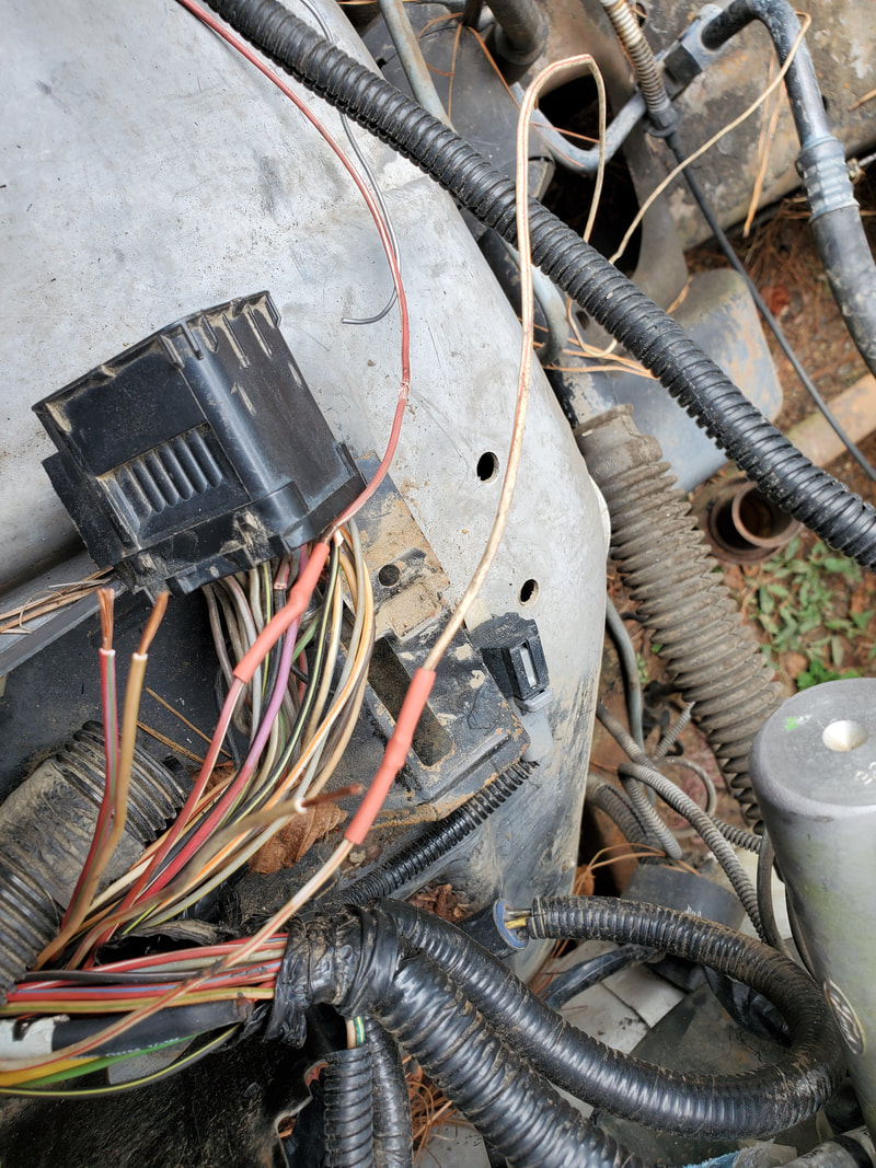
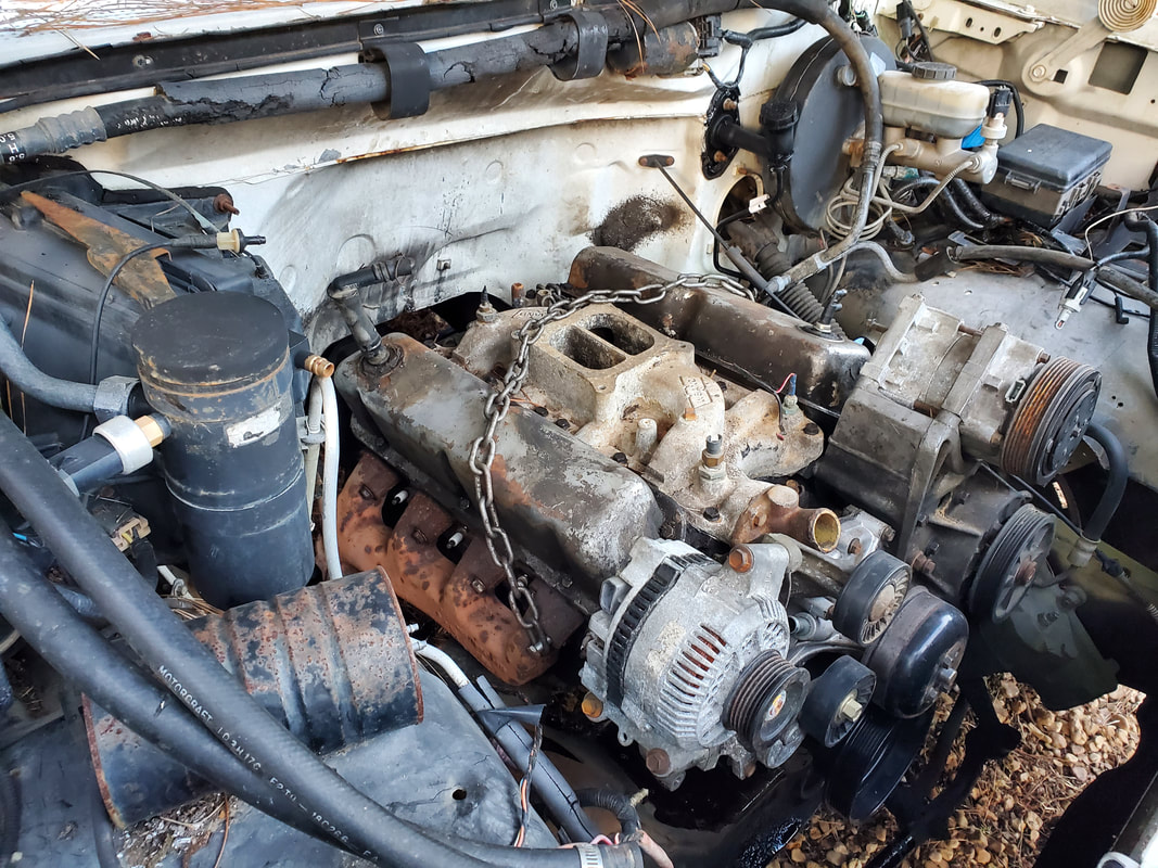
Engine bay with all sorts of hoses and wires and stuff scattered everywhere.
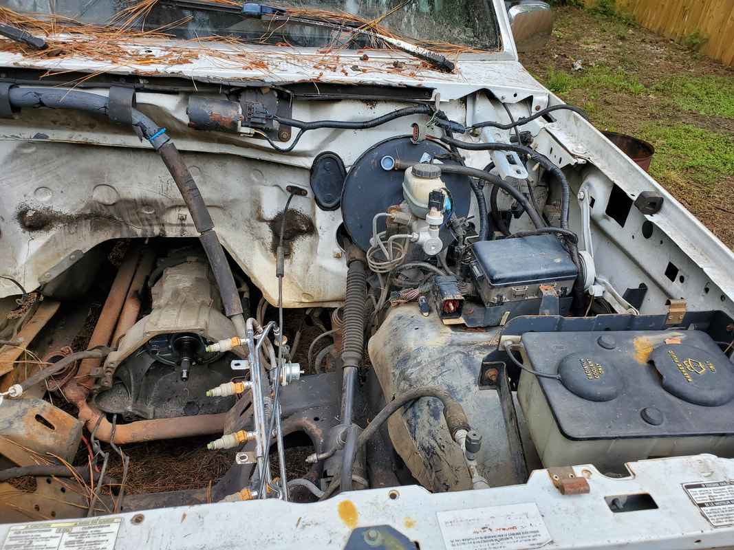
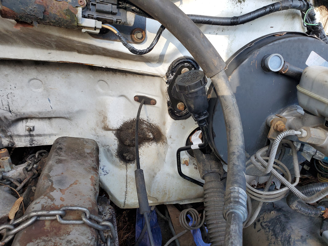
Driver's side of engine bay with EFI fuel rail still present. Note plugin front of master cylinder where wiring harness used to be.
Passenger side of engine bay after removing charcoal canister and more wiring.
Removing all of the unneeded hardware did clean things up quite a bit under the hood as there's no longer a bunch of wiring and other extra hardware. When I put the new engine in place, the only wiring present will be the wires for the distributor and for the temp and oil sensors. There will only be a few vacuum lines, one between the dizzy and the carb, one for the power brake booster from the carb, and one for the HVAc system, three lines, nothing more.
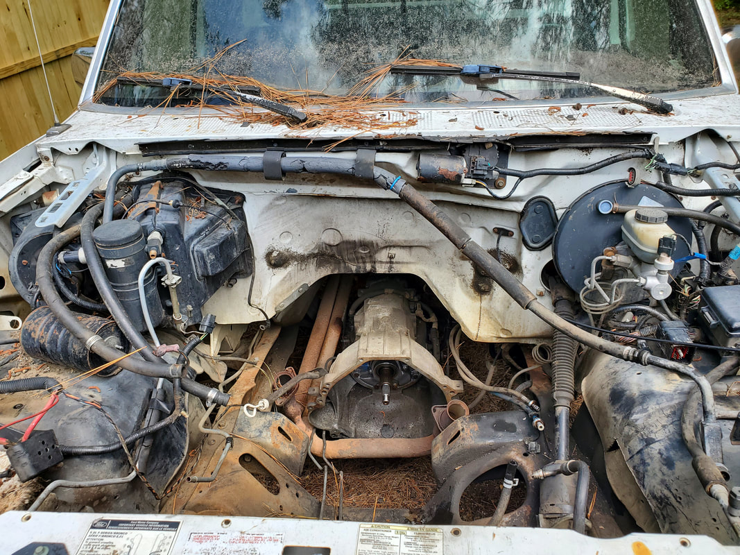
Engine bay cleaned up of unneeded hardware.
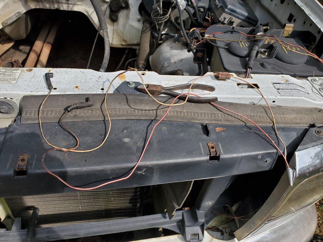
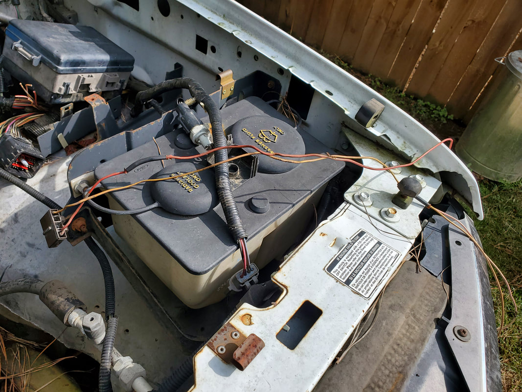
With the engine bay cleaned up of the wiring harness, I will have to take time later to isolate those couple of wires in the plug for the oil and temp sensors as well as an ignition line for the new dizzy that will stay on during startup. Whatever wire fed the old EEC distributor will be what I'm looking for as power would've needed to stay hot between startup and run conditions. I may have to do some probing with a hot battery in the truck while metering things to see where power is at and do some schematic searching to see what wires going to the engine bay feed the temp and oil pressure sensor circuits. Once those little hurdles are jumped, everything else will be downhill from there when it comes to the electrical system on the truck.
Another area I turned my attention to was just general cleanup. This involved removing the parts that were removed from the engine that were sitting in the cab and the bed of the truck. There was also some miscellaneous trash in the bed that needed to be cleaned out just so I don't have to be in close proximity to it while working on the truck. The extra parts will more than likely be put up for sale to someone who may put this stuff to better use than me. I would hate to scrap this stuff when it can still be used.
Excess parts pulled from engine bay.

EFI engine parts removed from old engine.
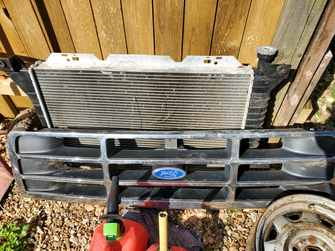
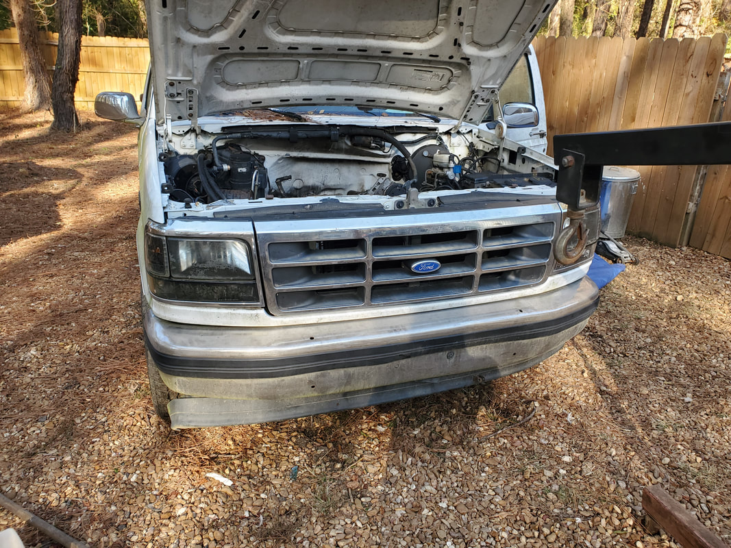
Grille and radiator moved out of the way to prevent damage while working on the truck.
Removing the garbage from the bed was a matter of scooping the actual garbage into a couple of large bags for disposal later while the humus and pine needles and other trash were raked out through the back and followed up with a garden hose all over the bed to wash out the dirt and other smaller debris from the bed to ensure a cleaned out bed. With that, I can smile and rest easy knowing the truck does not have garbage inside it, either in the cab or the bed.
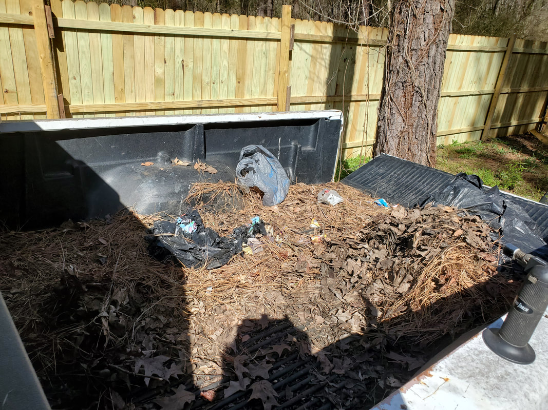
Bed full of trash in need of cleaning out.
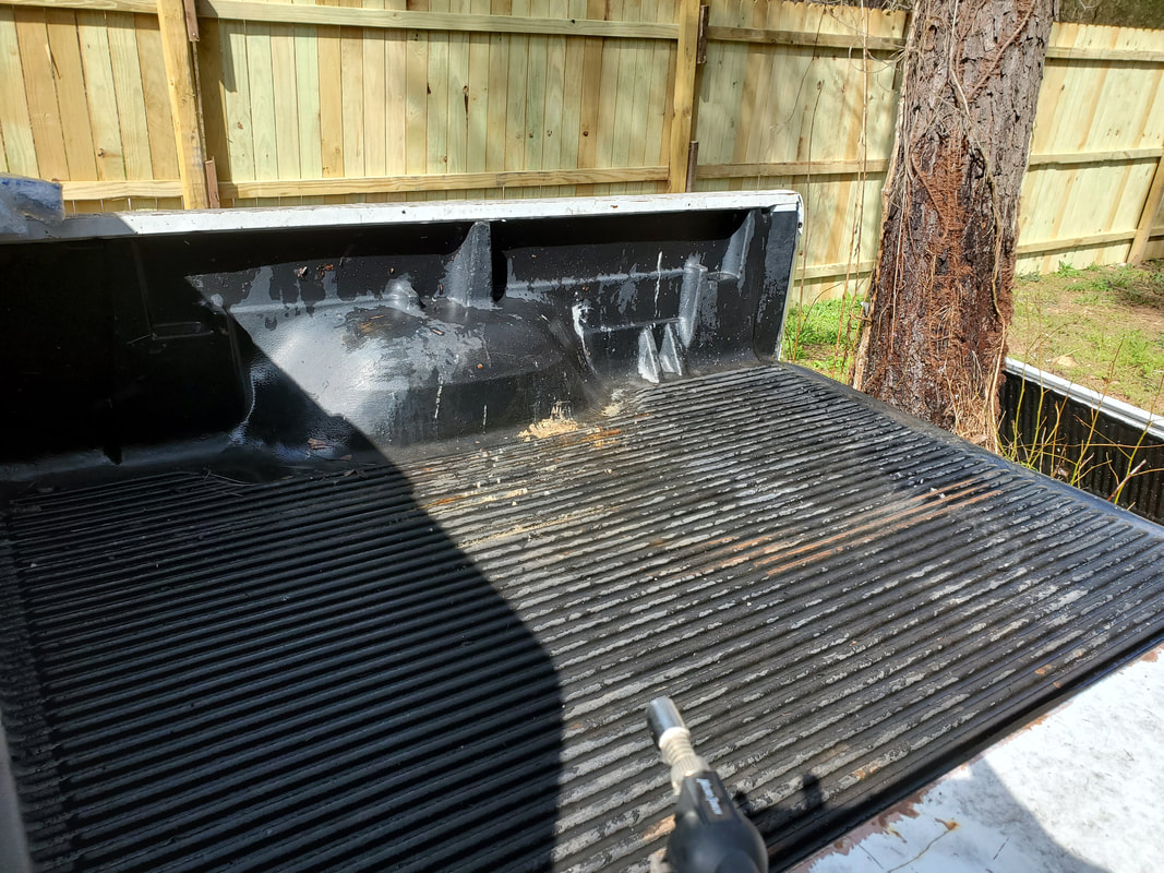
Cleaned out bed, on to the next order of business.
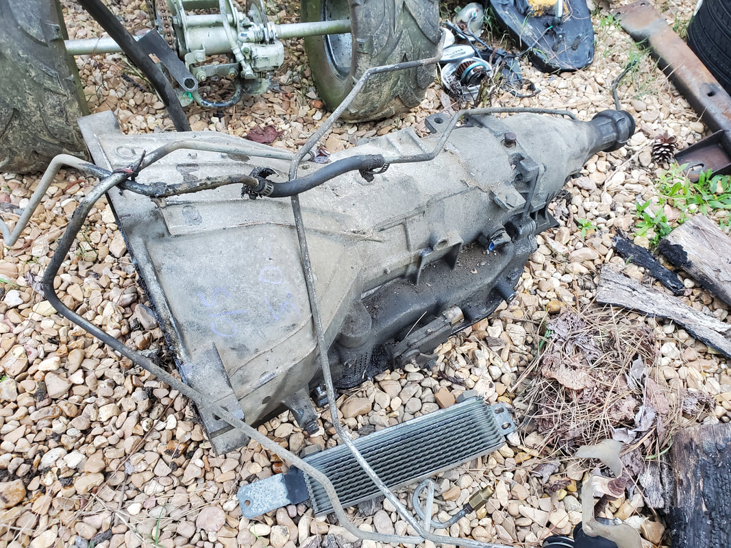
The next order of business is to remove the E4OD transmission. Since the unit is not needed in this truck, getting it out of the way and hopefully sold to someone who can use it will help in funding the rest of the project. Pulling the crossmember will get the unit to the ground. Since the oil lines are already disconnected and won't be needed, they too can come out, which will further de-clutter the underside of the truck.
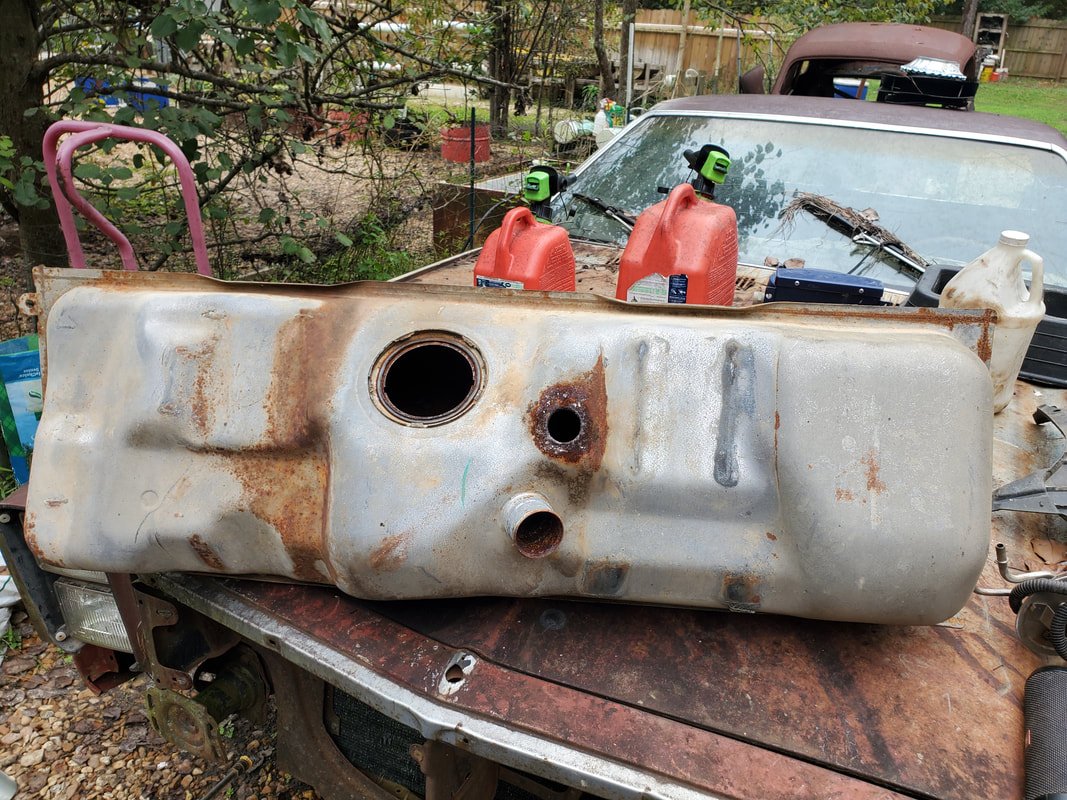
As part of the build of the FMT I will have to make some serious changes to the truck's fuel system. Since the truck was originally an EFI system that uses high pressure fuel pumps to feed the EFI system, I have to deal with a double fuel line system consisting of a heavy duty fuel line and a return line, going to a fuel pump/sending unit assembly that consists of the high pressure fuel pump and sending unit. The sending unit has a pigtail for the two sets of wires and uses the lock ring system for securing the fuel lines to the nipples on the unit. Also the truck has two fuel tanks, each with its own sending unit assembly. To switch tanks, the truck will just turn off one fuel pump and activate the other pump to feed the system. All of this stuff has to change.
My plan was to delete the rear fuel tank completely, and replace it with a spare tire winch mechanism that you would typically find in SUV's and some trucks. This again, will allow me to stow away the spare tire under the bed versus laying it loose in the bed. Leaving the front fuel tank, I will still have to make changes since we're not going back to the EFI system but instead will be using a standard mechanical fuel pump on the engine block drawing from the fuel tank at lower pressures. All of this only requires one simple metal fuel line coming from the sending unit going to a fuel filter and into the fuel pump then into another fuel filter before going to the carburetor. Most installs don't have a fuel filter before the fuel pump, but I would actually like to install a higher performance pump so I can have the ability to feed a bigger carburetor whenever I upgrade the engine in the future.
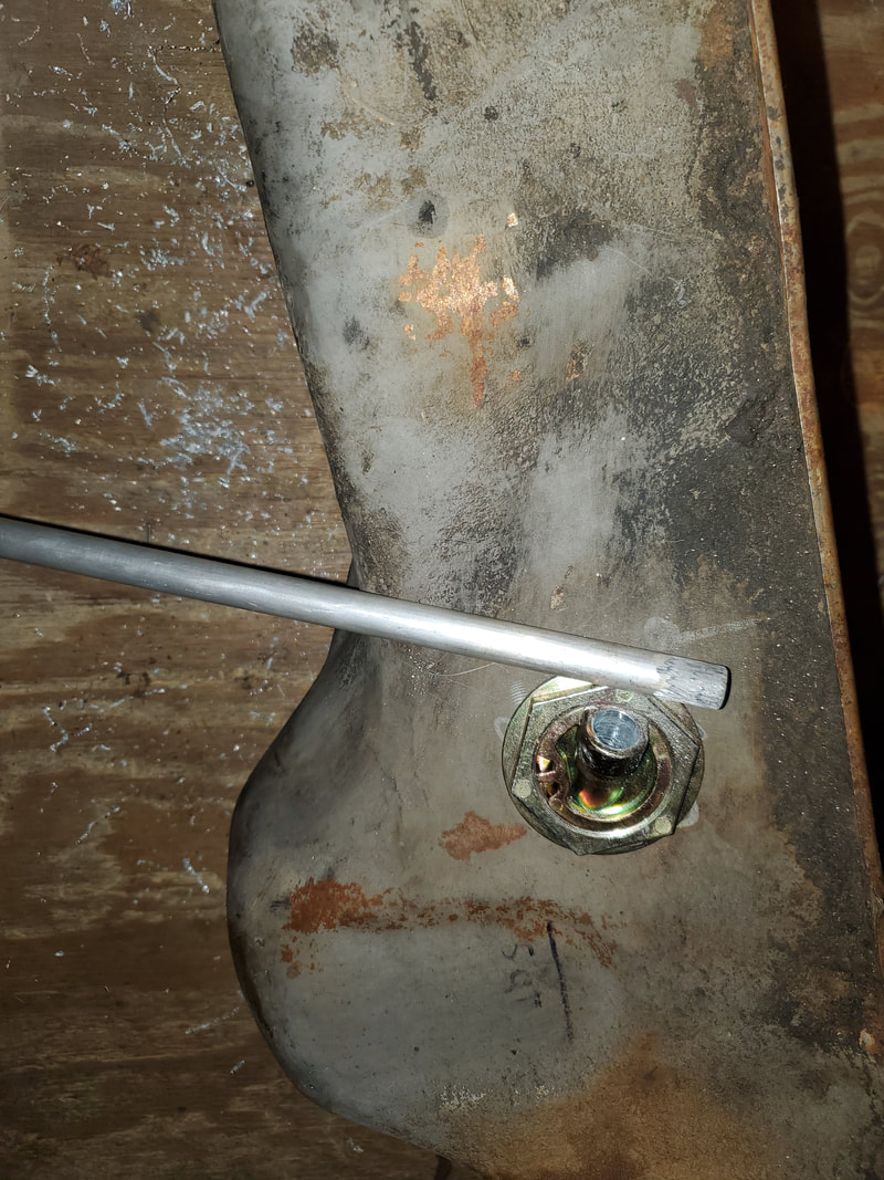
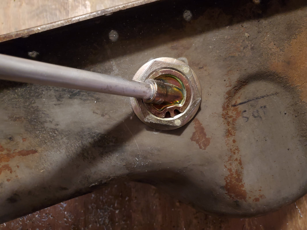
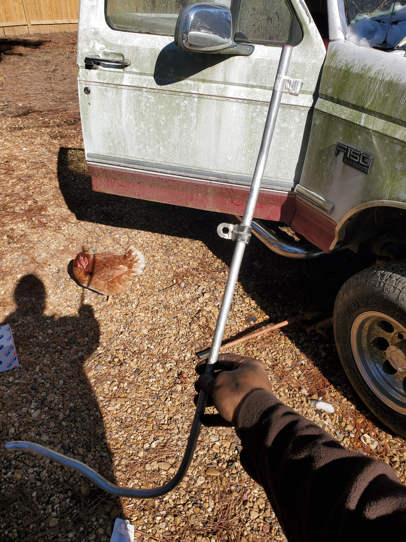
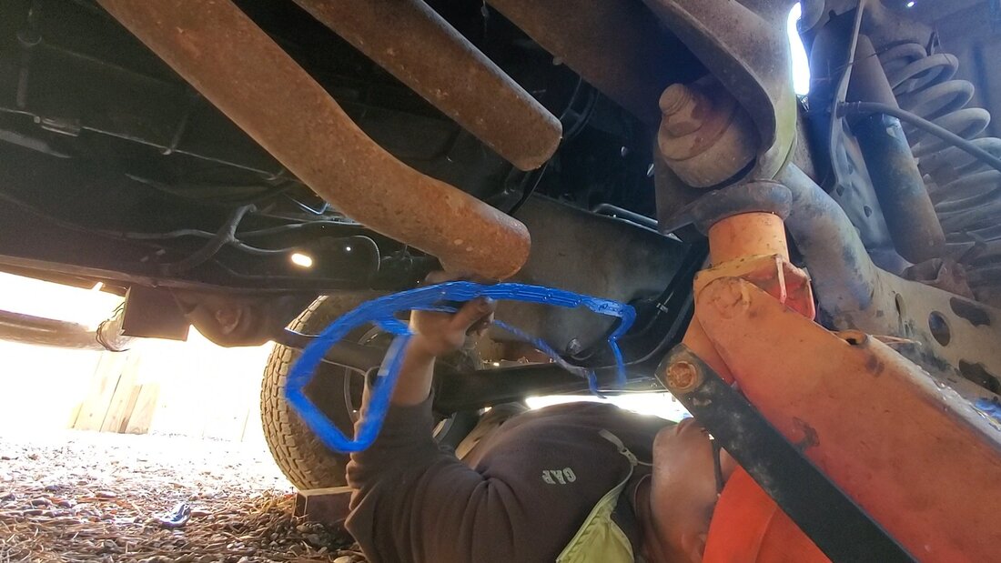
To start the job I have to target the rear fuel tank. The tank is held in with two straps across the bottom of the tank. The bolts holding the straps in were pretty well rusted and required the impact wrench to break them free. The straps each had a bolt on either end that had to come down to allow the tank to drop. One strap came loose easily but the other one had one bolt that was blocked by the aftermarket dual exhaust system. After trying to take the bolt and nut lose with a pair of wrenches, in vain, I just said screw it and grabbed the reciprocating saw and cut the strap in two to get it loose. After getting the strap loose I was able to maneuver the tank down to the ground.
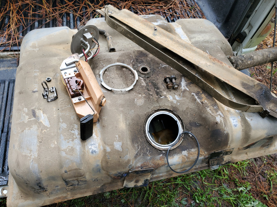
With the tank on the ground there was still a matter of removing the sending unit since I would have to work the lock ring tool into the hose to separate the hose from the nipple on the sending unit. This would be much easier to do if it wasn't stuck in the fuel tank while it was at an angle. I undid the lock ring holding the sending unit in the tank and pulled the unit free from the tank, allowing me to remove the tank all together from under the truck.
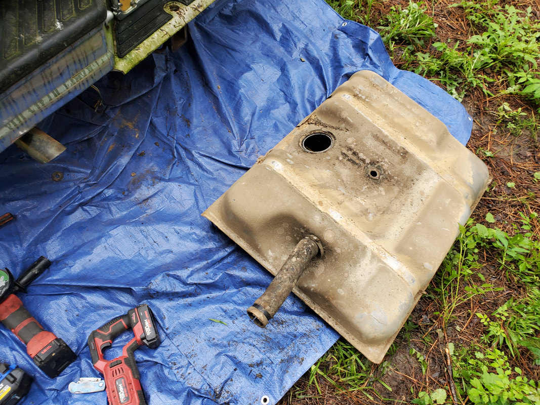
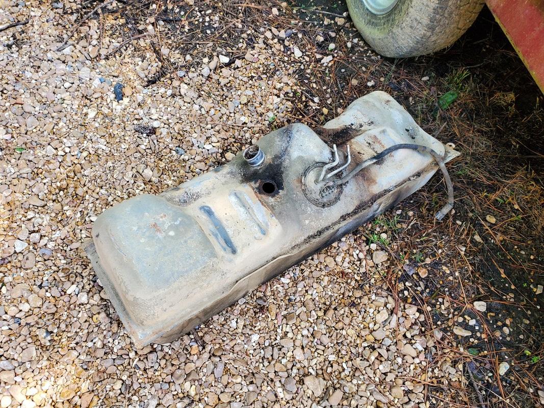
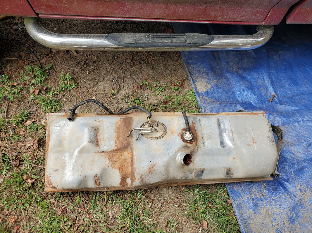
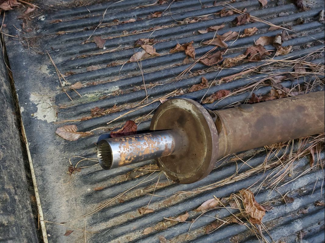
Fuel tank removed from under bed of truck. Note filler hose on end of tank.
With the tank out of the way I went back under the truck and used the tool to separate the hoses from the sending unit. Despite the bolts holding the straps being almost rusted together and dirt being present everywhere, the lock rings came loose with a minimum of effort compared to past episodes with these things. After removing the hoses from the sending unit the plug was pulled from the pigtail on the sending unit so I could get that out of the way just as well. I then removed the top halves of the straps for the fuel tank since they would not be needed and would actually be in the way when I install the spare tire winch under the bed.
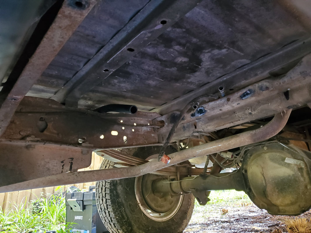
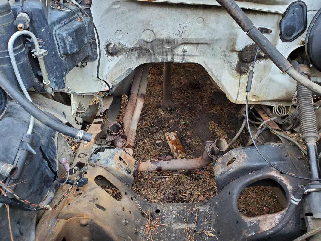
Underside of bed sans fuel tank.
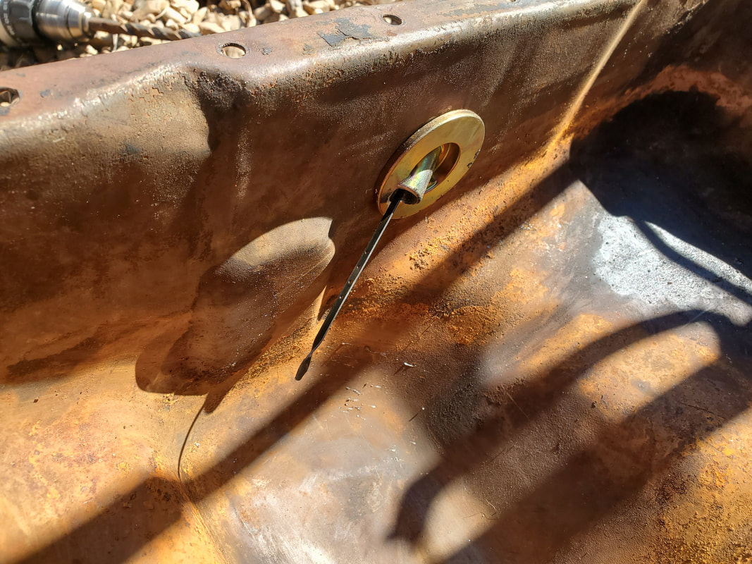
With the tank, sending unit and retaining straps removed from under the bed, I turned my attention to the fuel filler hose. I already had to cut a slit at the end of the rubber tube attached to the fuel tank to allow it to pull free easily from the filler tube so I didn't have to worry about that. But the filler tube is held in by three 7mm bolts, and a hook under the bed that is clamped by a worm clamp around the filler tube. After pulling all of this free I had the filler tube completely removed from the quarter. I removed the gas cap just as well and put it with the filler tube for when I put these items up for sale later.
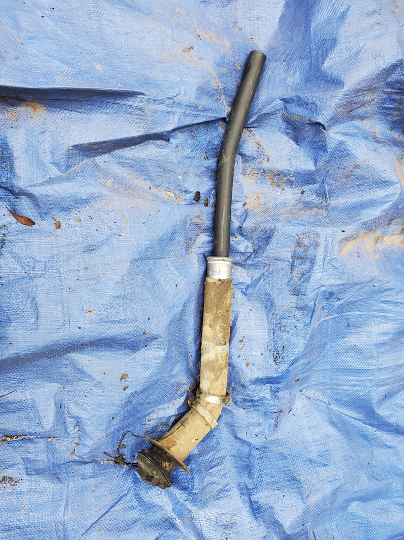
Fuel filler tube removed from quarter panel with gas cap included.
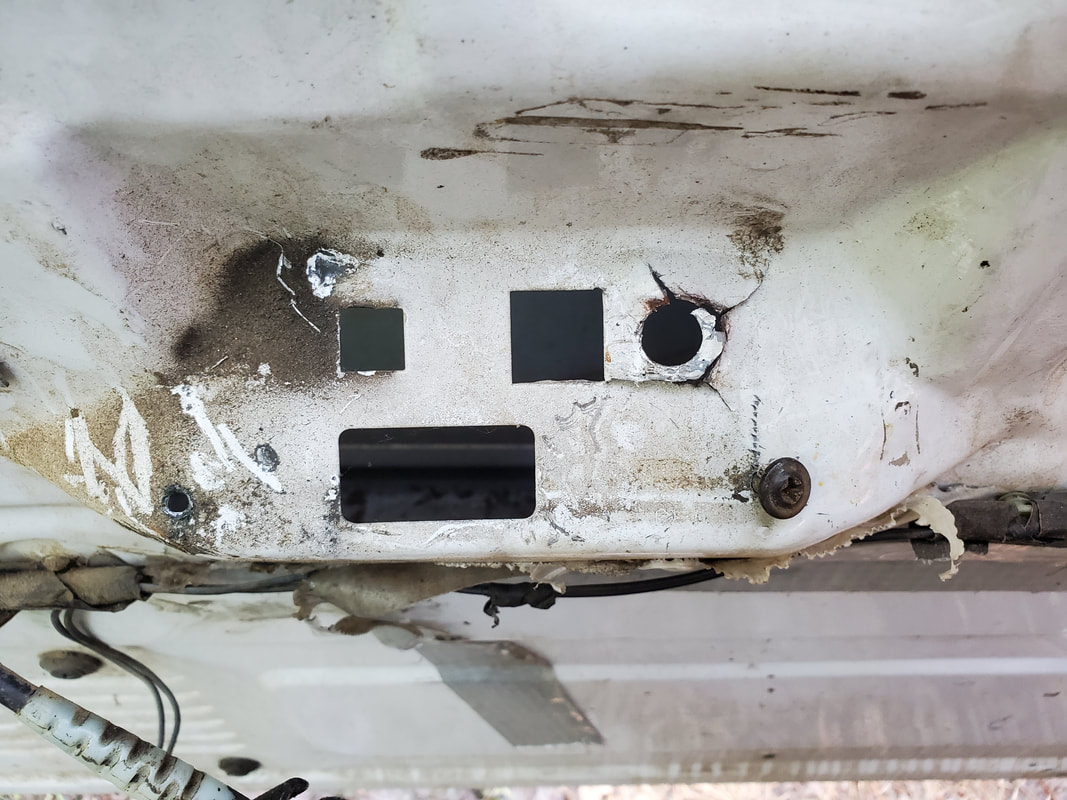
One might ask, "What are you going to do with the opening behind the rear gas door?" I had an idea that stems from a thing I did with the LUV a long time ago to extend the truck's utility beyond just hauling stuff. I had installed a power inverter behind the seat in the LUV along with a quad outlet box which would allow me to plug up extension cords for running things outside the truck, or plugging things up inside if I was doing something inside the truck. Well fast forward to today, and that idea still held some weight, but with a twist. I thought about fabricating an outlet box that would hold a single outlet within but would bolt up to the opening where the old filler tube was sitting at. I would of course have to install an outlet wiht a waterproof cap to keep it protected from moisture but it would otherwise be behind the gas door. I would then run a power cable from the outlet along the bed over to the cab and inside the cab, terminating at a power inverter installed within. I'd have a power switch operating a relay to cycle high amperage power from a pair of cables running from the battery to supply power for the inverter, since I would probably have at least a 500w inverter in there that would allow me to run most power tools and other small devices that might be used in the field. This would allow the FMT to pull extra duty as a worksite power source or emergency power source, or a campsite power source while still being a hauler and an overall fun riding truck.
Fuel tank and miscellaneous parts removed from under the truck.
After having pulled the rear fuel tank from the FMT, I was still tasked with the removal of the front fuel tank. Unlike the rear tank, I'll be keeping the front tank as part of the modified fuel system, which as stated before will consist of just having a regular single fuel line going from the output of the sending unit over to the left side of the engine bay where it will link up to the mechanical fuel pump on the left side of the engine. The sending unit itself will be modified by deleting the pump motor and capping off the return port then capping off the port on the top of the tank for the evaporative fuel return system.
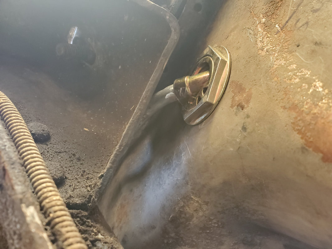
As before, removing the front tank started with removing the two straps holding the tank in place. Also as before, due to the caked on dirt and rust, I had to use the impact wrench to break the nuts to remove the bolts. After removing the straps I was able to lower the tank enough to be able to remove the filler tube and evaporative fuel tube from the top of the tank. Lastly I unplugged the sending unit pigtail and popped the accursed lock ring fittings for the two fuel lines on the sending unit. With that the tank was down and out.
Front fuel tank removed from under truck.
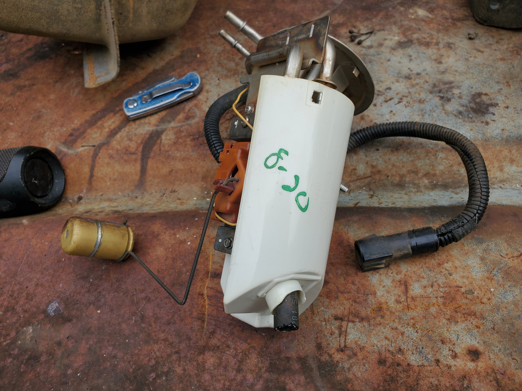
With the tank on the ground I popped the locking ring to remove the sending unit. Unlike the rear tank's sending unit I was disappointed when I removed the unit to find it looked horrible. Between the rust and grime on it, the float for the sending unit was gone and the strainer was broken up bad. This sending unit even after removing the pump would probably not work. I'll have to replace it....because the rear sending unit will not fit....because...they're made different....
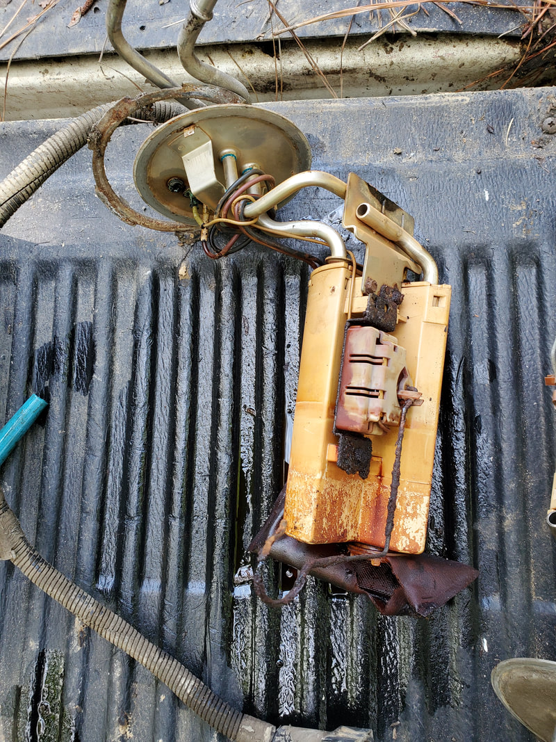
Old worn out sending unit removed from front fuel tank, useless...
After removing the shitty sending unit, I still had to remove the varnish called gasoline that was still in the tank. Luckily there was only about 5 gallons so moving the tank wasn't that bad. Because there was this much gas in the tank instead of trying to use a funnel to put the gas in a can I just used an old bucket and dumped it in, then dumped it from the bucket into a dirty old diesel fuel can using the funnel. I'll end up mixing this old fuel with old oil to use for brush pile fuel or for starting a fire pit.
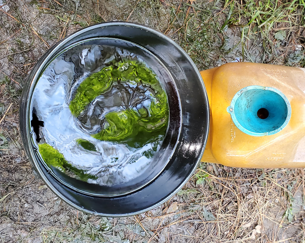
Five gallons of old gas removed from tank, ready to pour into old diesel can.
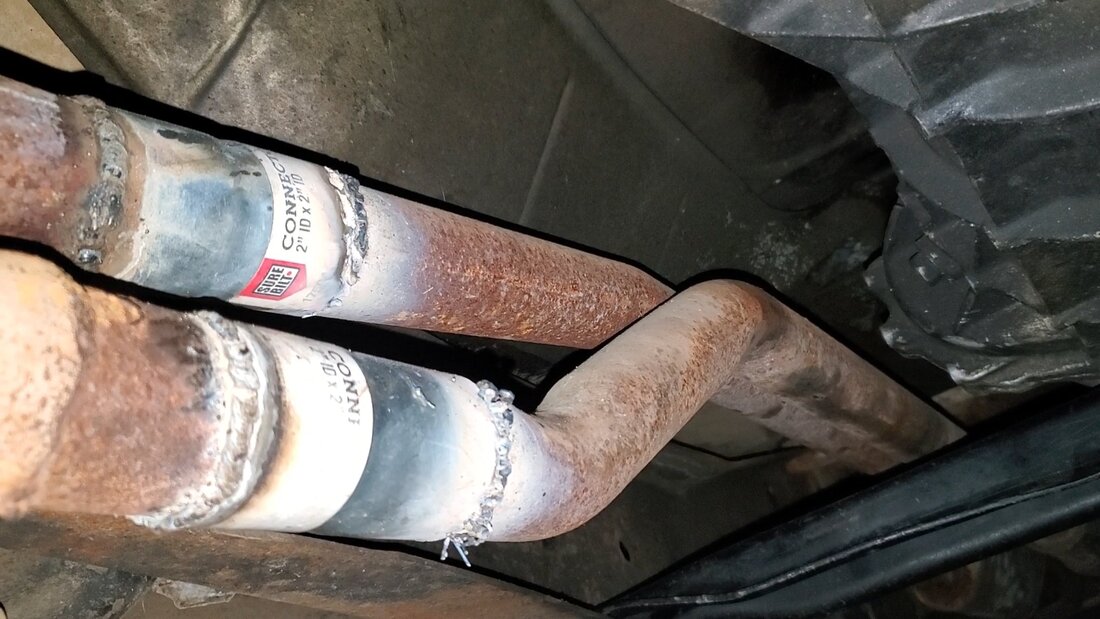
After taking care of the fuel the last thing was removing the old fuel lines from under the truck. I was at least pleasantly surprised to find that the lines were held up by simple clamps versus straps held in with bolts. Also the previous owners in the process of replacing the fuel filter because they didn't understand how lock rings work or how EFI fuel systems work and their requirements, they just cut the lock ring fittings that would normally go to the fuel line and used worm clamps to clamp the hose on both sides to the nipples of the fuel filter. That this thing even held is beyond amazing to me since the pressures on this EFI system can reach 40 psi. Anyway, there was one other lock ring fitting I had to break to separate the fuel line at the midway point. After removing that I and the worm clamps I was able to remove the fuel lines in sections from the front going back. I cut the rubber hoses for the evap fuel lines since they aren't that important enough to try and save. I had to do a little manipulating of the tubing and lines to get them pulled free but it didn't really take that much effort to get the lines out. Even the evap fuel tubing didn't take much effort to remove as it too was just held up by snap hangers in the frame rail. Everything came out quick and dirty.
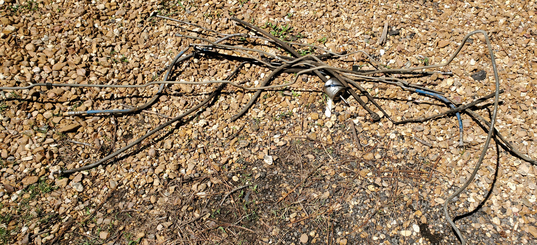
Old EFI fuel lines removed from under truck.
One other twist I found was that the evap fuel line I removed, being 3/8" tubing was very long, reaching from the middle of the fuel tank across the underside to the right side and along the right frame rail over to the right side of the engine bay where it hooked up to the charcoal canister. Being this long had me thinking. I started straightening the line as best as I can, sometimes using a baby sledge to try and straighten the sharper bends. After getting the line straightened as much as I can, I found that it was plenty long enough to reach from the fuel tank to the left side to hook up to the engine's fuel pump. This is perfect as I don't have to waste any money buying fuel line to install later for the new fuel system, perfect.
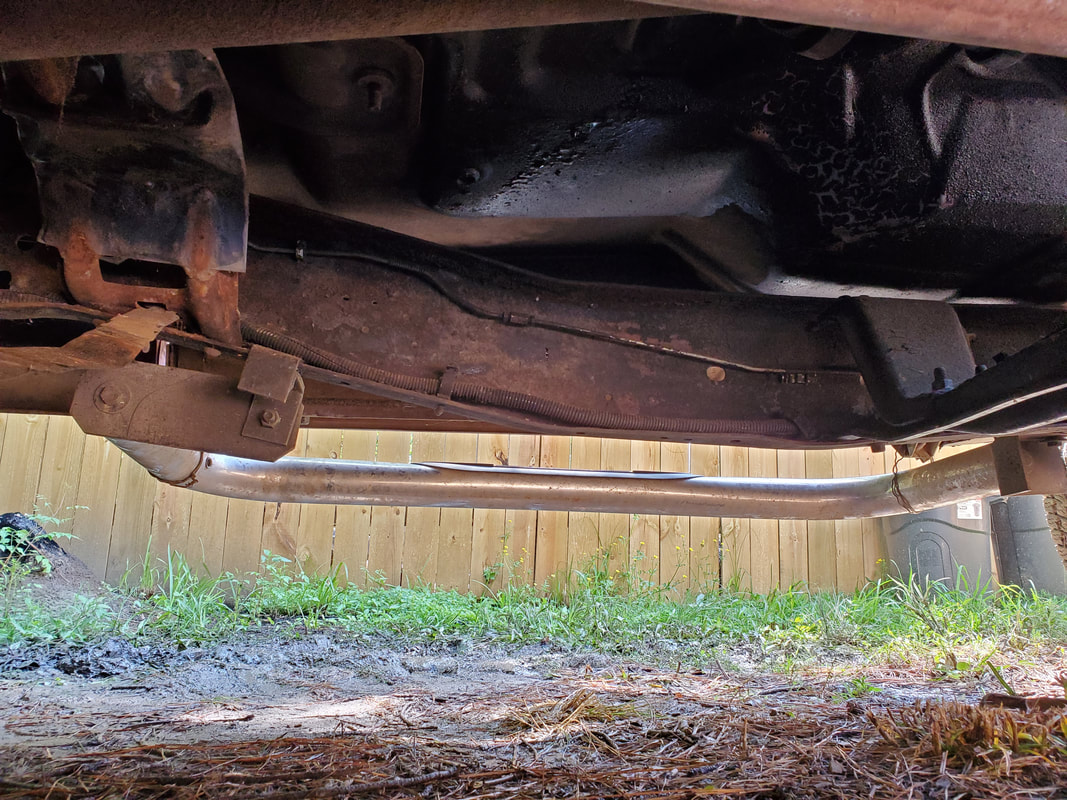
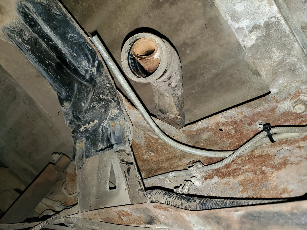
Underside of truck cleared of front fuel tank and fuel lines along frame rail.
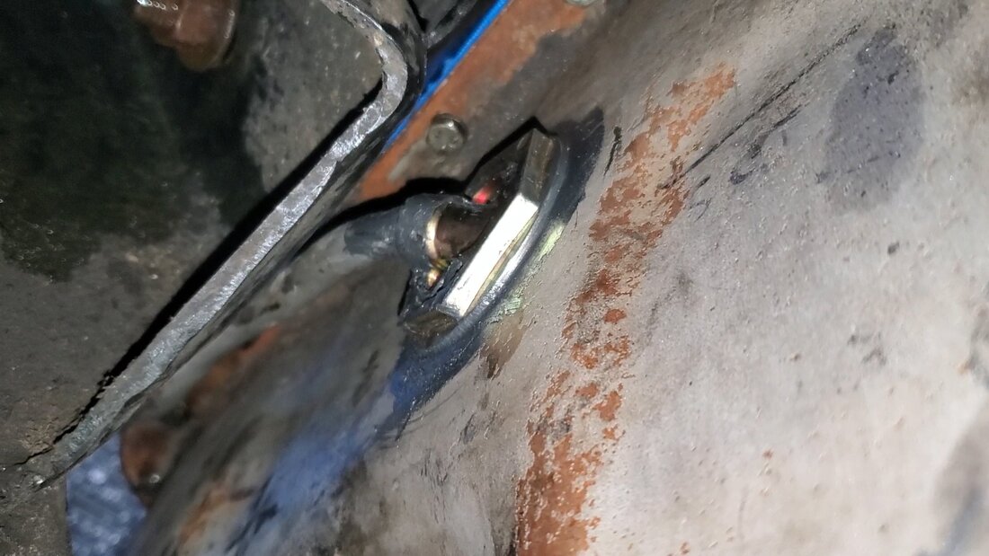
After having pulled the old fuel system out from the FMT, I was able to recycle a piece of metal tubing that went for the evaporative fuel recirculation system. This line was plenty long enough to go from where the front fuel tank is located over to the front of the engine compartment at the left side where the mechanical fuel pump is on the engine block. Also since I pulled the old lines from the frame rail, there was a good spot to put the new line since the brake line was the only thing up there along the rail. I took time to straighten the line as much as possible and went ahead and slid the tubing in, making sure to have it routed right along the frame rail, going under any metal supports then snapping the tubing in place where I could while using zip ties to secure the tubing to the brake line. From there I bent the tubing to terminate above the fuel tank, well where the fuel tank would be located when I reinstall it. I topped things off by cutting the excess tubing off. I bent the front end of the tubing to have the nipple terminate along the spot where the fuel pump will be. All I have to do is add a short piece of rubber hose to link the two.
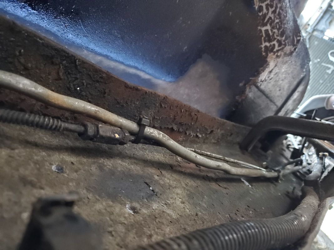
Fuel line routed along frame rail and secured to brake line with zip ties.
Back end of fuel line bent over to meet up with top of fuel tank when its reinstalled.
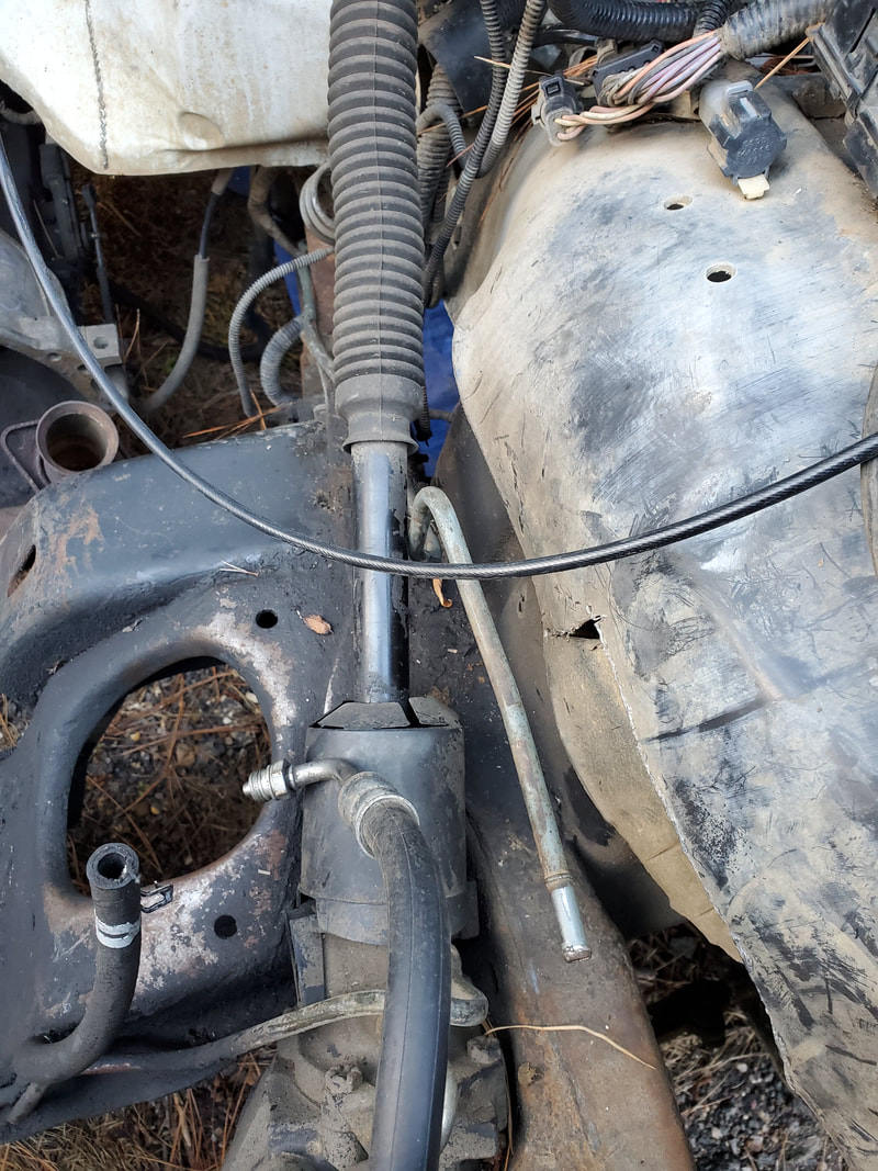
Front end of fuel line routed up through engine bay over to where it'll meet up with block mounted fuel pump.
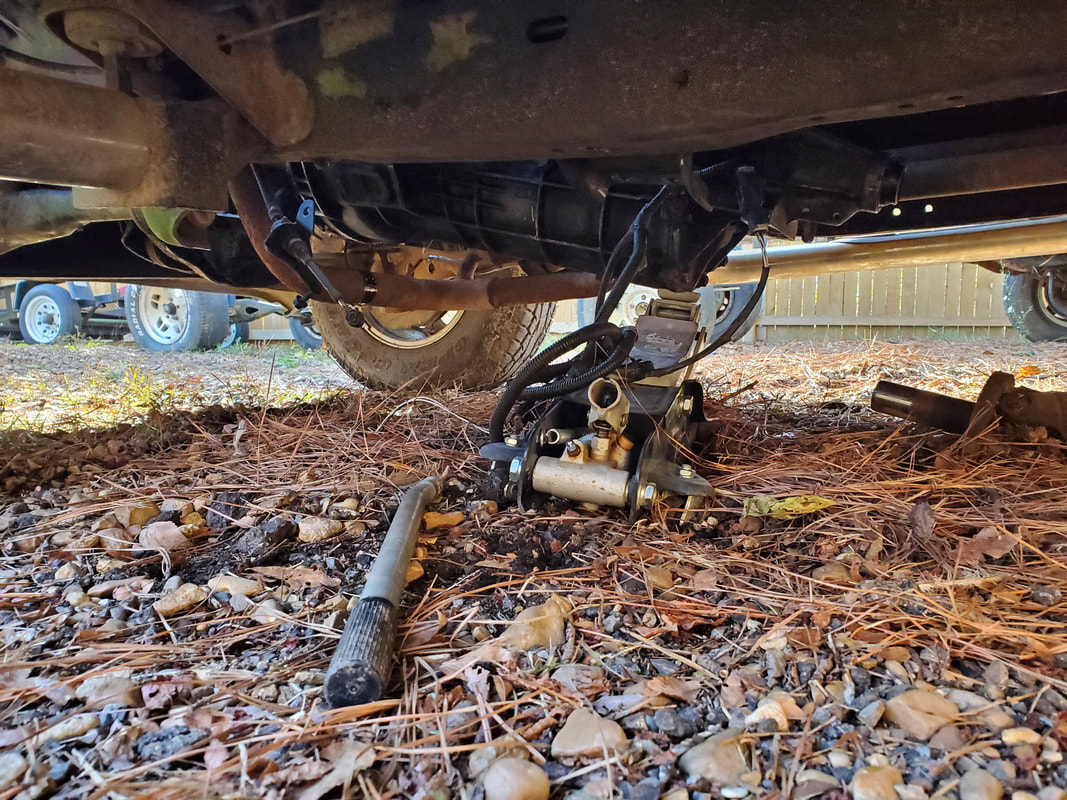
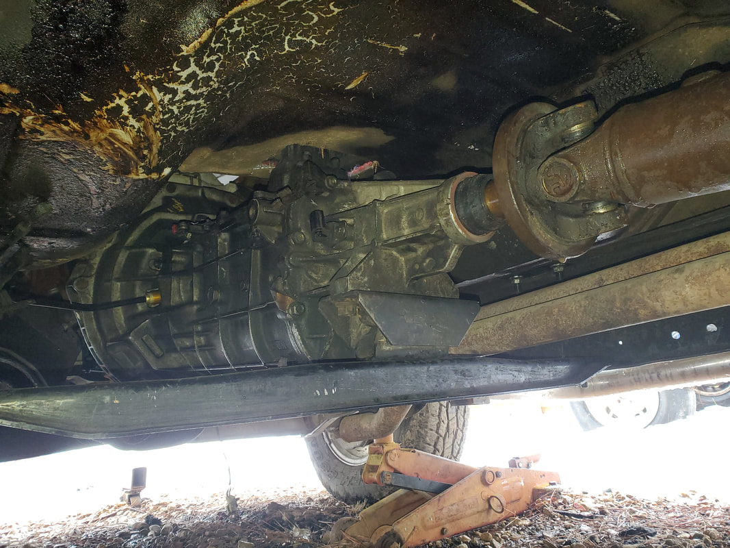
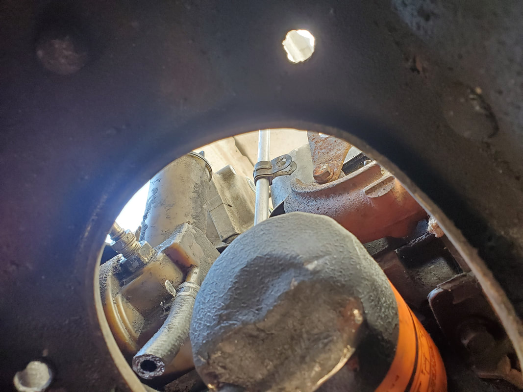
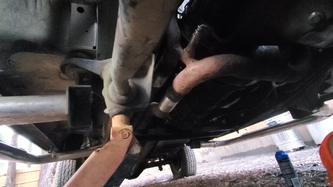
The next order of business was to remove the E4OD transmission that was still in the truck. It was still mounted to the crossmember and had the shifter linkage still hooked up. The oil lines were still present as well. The first thing I had to do was disconnect the crossmember from both the transmission and from the frame rails before I could be able to get the tranny to the ground.
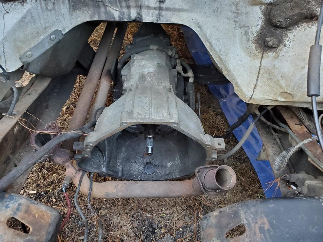
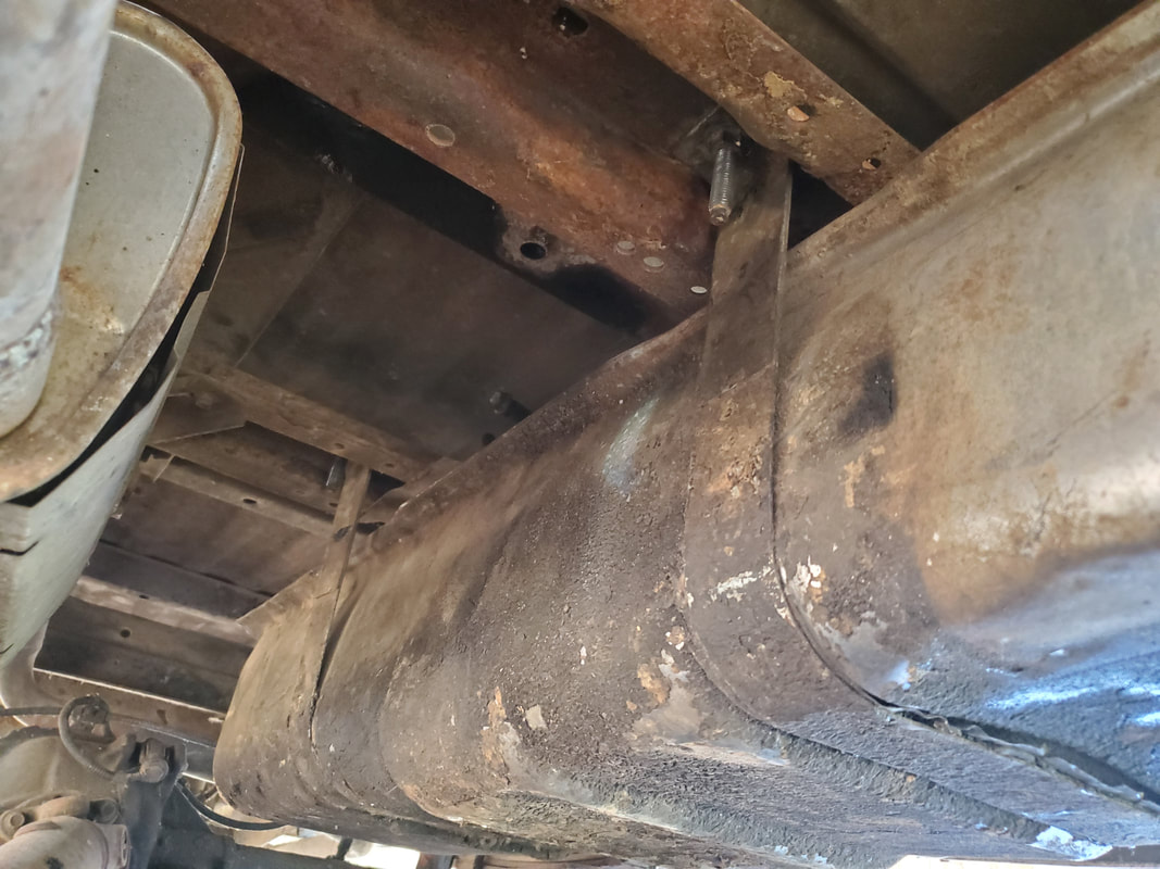
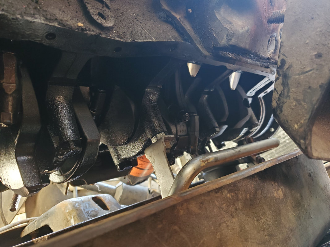
E4OD transmission still in place under truck.
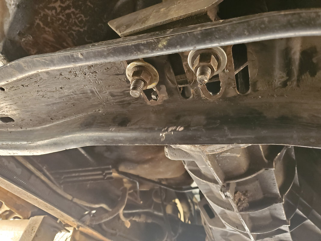
I had to fight the bolts that held the crossmember in place. There was a single bolt that held either side of the main crossmember in place to the frame rail. Those bolts came loose easily. Then there was a secondary crossmember that went from the main crossmember up to the top of the frame rail. The two bolts at the top of the frame rail were a PITA since I couldn't get to the bolts with the impact wrench, I had to use the regular socket and ratchet. That took a minute and since I couldn't get the bolts out (thanks Ford for the stupid design) I just loosened the bolts up enough to be able to move the secondary crossmembers from the main so I could move the main out of the way. I had to jack up the transmission first to clear it of the crossmember after I pulled the nuts free from the tranny mount. With the crossmember out of the way I was able to slide the tranny to the ground. After that I removed the oil lines and the shifter linkage from the transmission and unplugged the wire harness from the unit. I slid the tranny forward enough to pull the driveshaft yoke free. Once everything was free I slid the transmission towards the back where the frame rail angles up, allowing me to work the transmission out from under the truck.
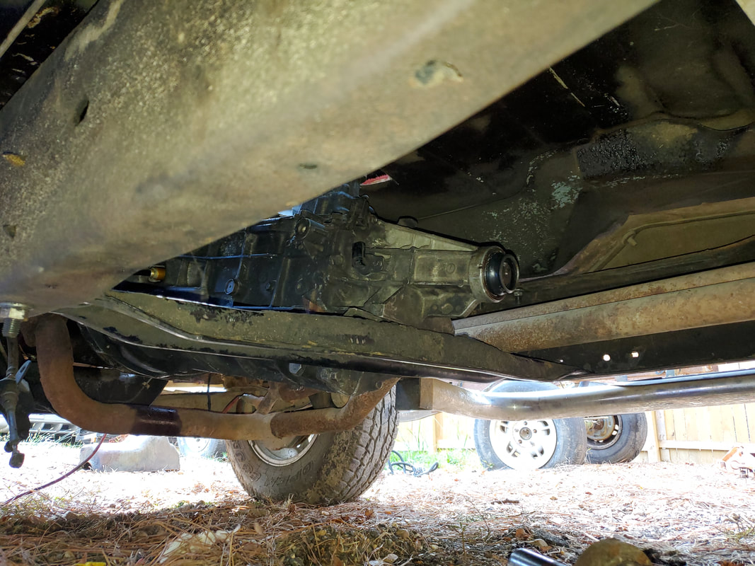
Transmission bay void of transmission, ready to accept manual transmission.
After pulling the transmission free of the truck I slid it over to the staging area where I had the other engine parts from the truck staged at. I took the fuel lines over there and even removed the extra tranny cooler from the front of the AC condenser since it wouldn't be needed anymore. Of course I'll be putting all this up for sale to recoup some of the money that had been spent on the project.
Transmission and associated components staged with other FMT parts pulled off earlier.
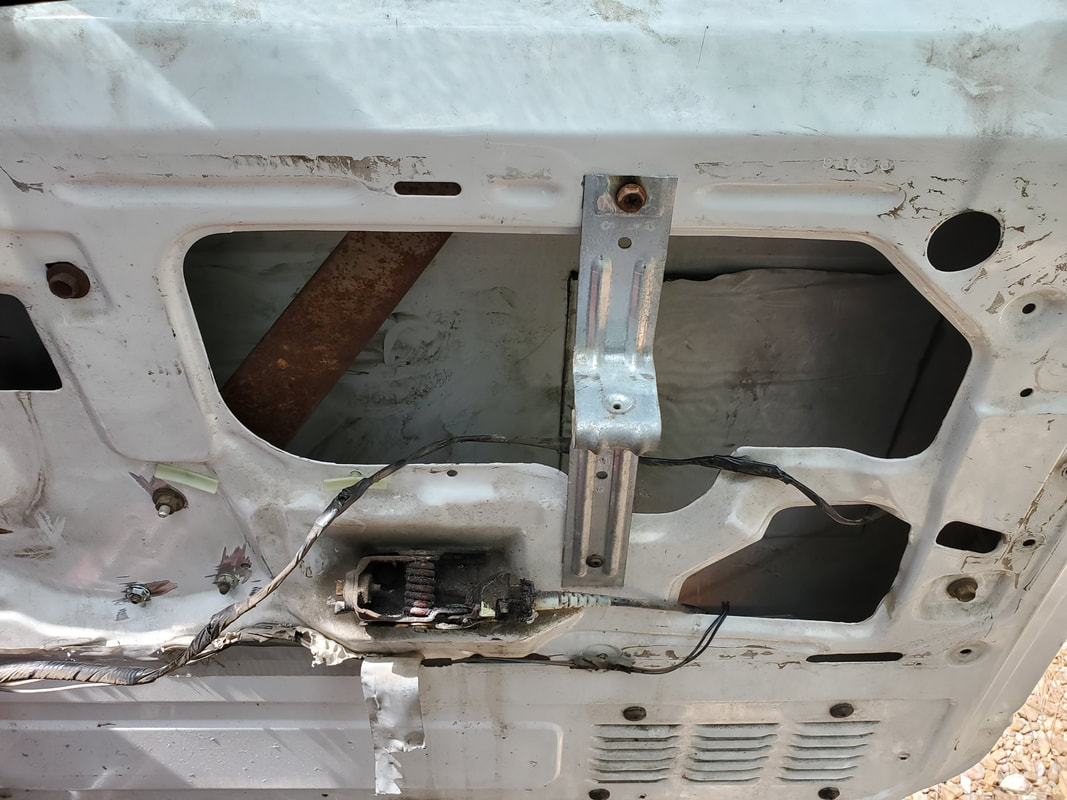
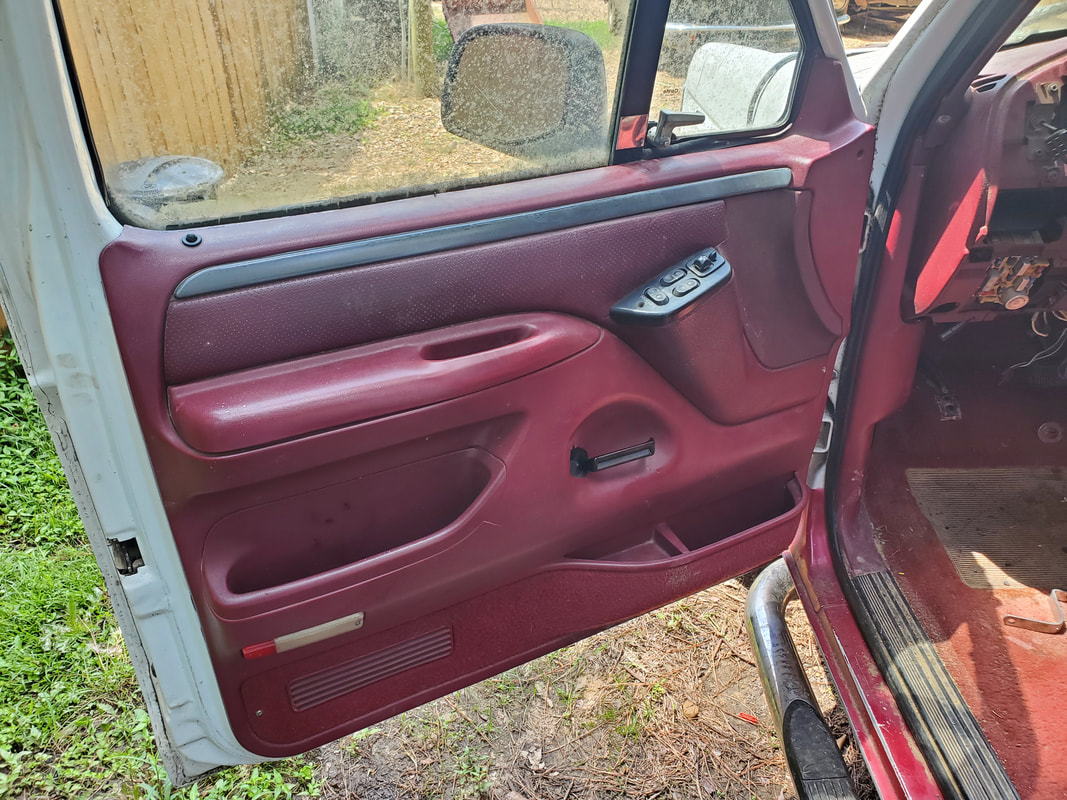
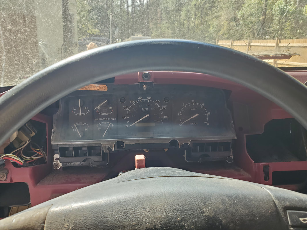
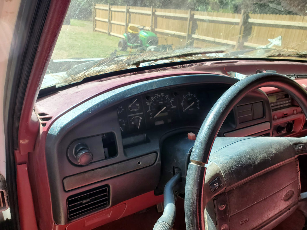
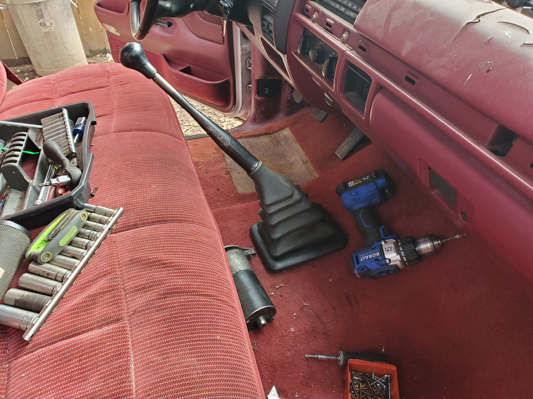
After pulling the transmission and rear fuel tank from the FMT, I turned my attention to the interior. Not necessarily the seats or carpet or dash but the doors as well as the gauge cluster and some miscellaneous hardware. The doors are currently missing the interior handles used to open the doors, with one replaced by an angle brace but for some reason was still unable to release the latch. The window regulator on the driver's door is damaged where it doesn't hold the glass up. I still didn't know if either window worked since there was no power on the truck's electrical system. Then there's a matter of the steering column and gauge cluster. There's no key for the ignition switch so I would have to somehow remove the tumbler assembly. The shifter handle needed to be removed along with the gear indicator in the gauge cluster. I also needed to remove a couple of indicator light bulbs so those lights won't be constantly on when the truck is running. Of course I still need to trace wires for the gauges so I can isolate those lines in the engine bay in order to properly hook them up to the engine.
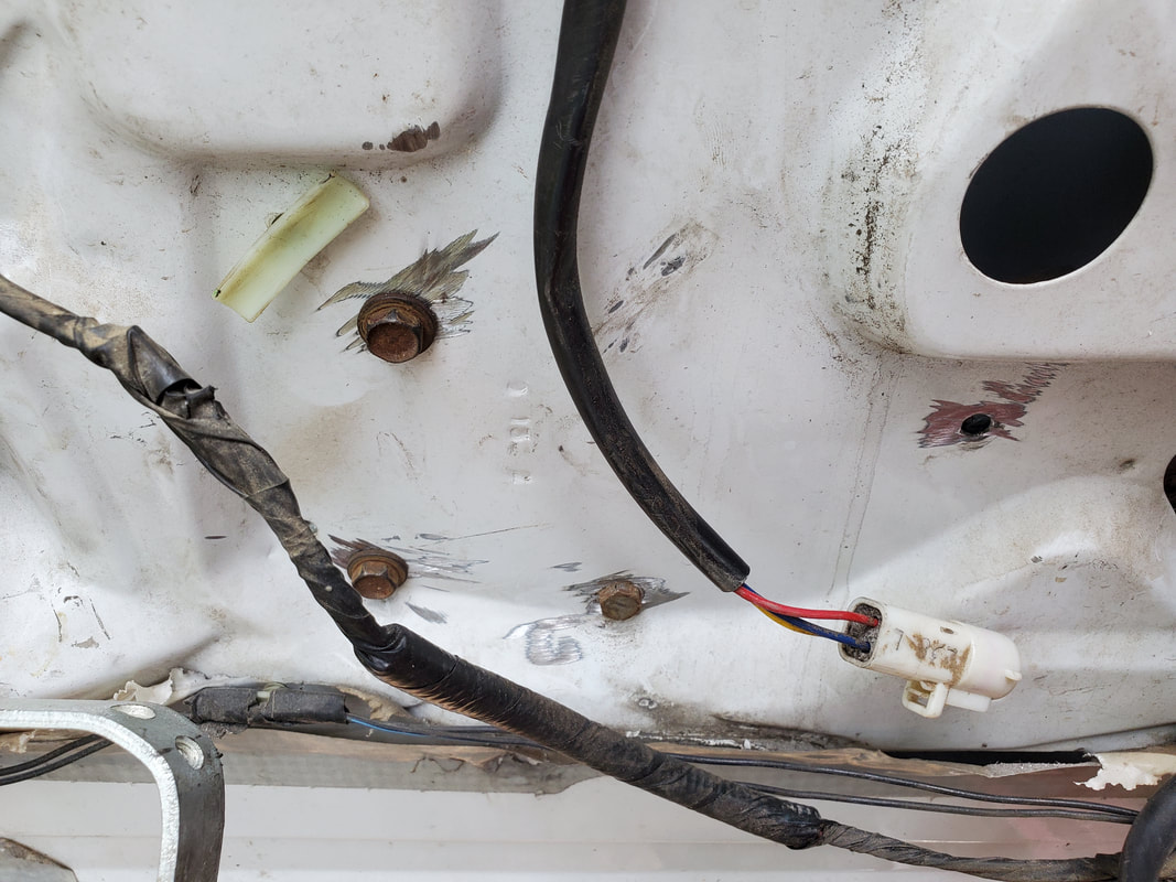
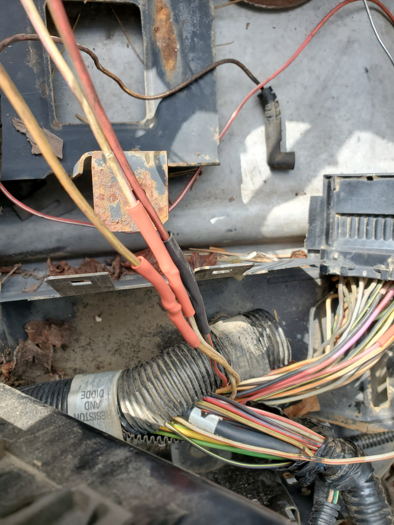
The first thing I had to do before going inside was check and see if the wire harness from the old E4OD transmission was a separate section of the overall wiring harness where I could unplug it intact where I could sell it off versus cutting it and having a bundle of bare wires somewhere under the floor that would've needed capping. Luckily I found that the wiring harness was terminated at a plug just under the brake master cylinder. Once I unplugged that, I was able to remove the whole wire harness for the transmission without any butchery.
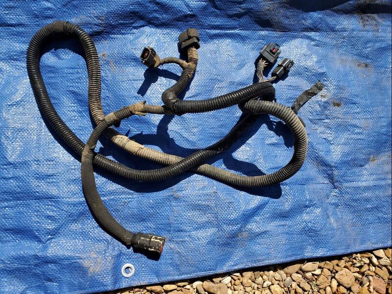
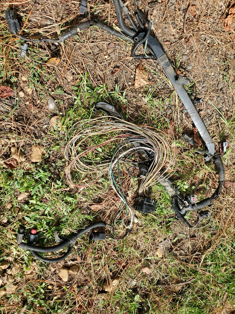
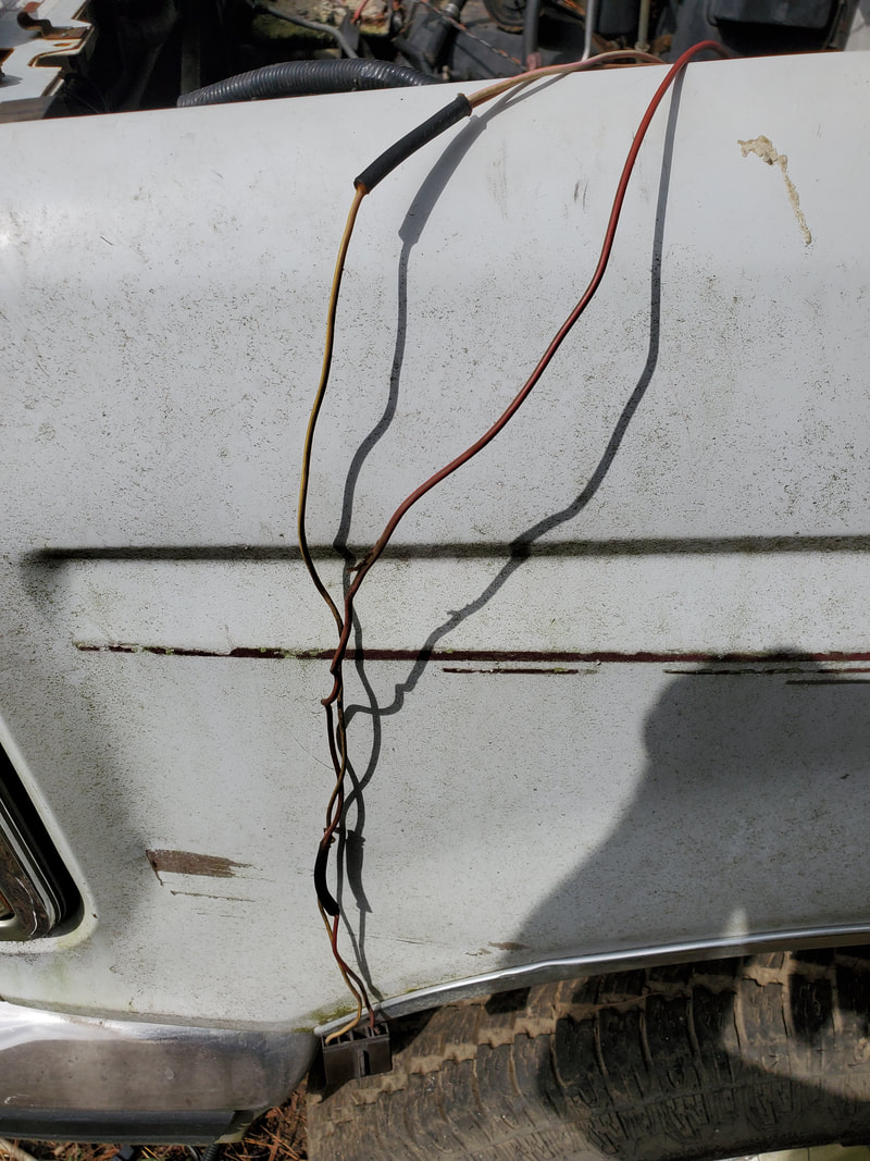
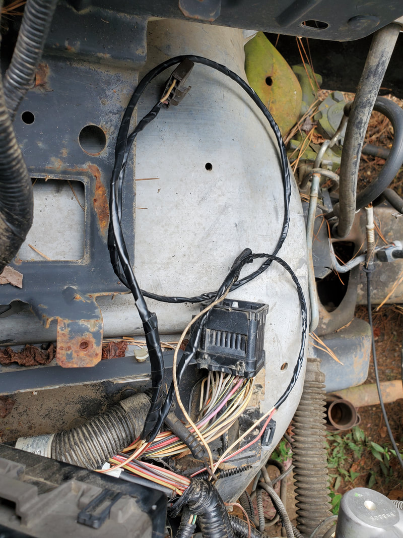
Tranny wire harness removed from under truck.
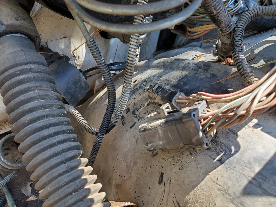
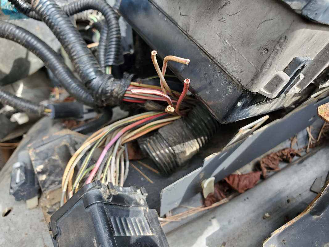
Plug junction where wire harness was plugged to.
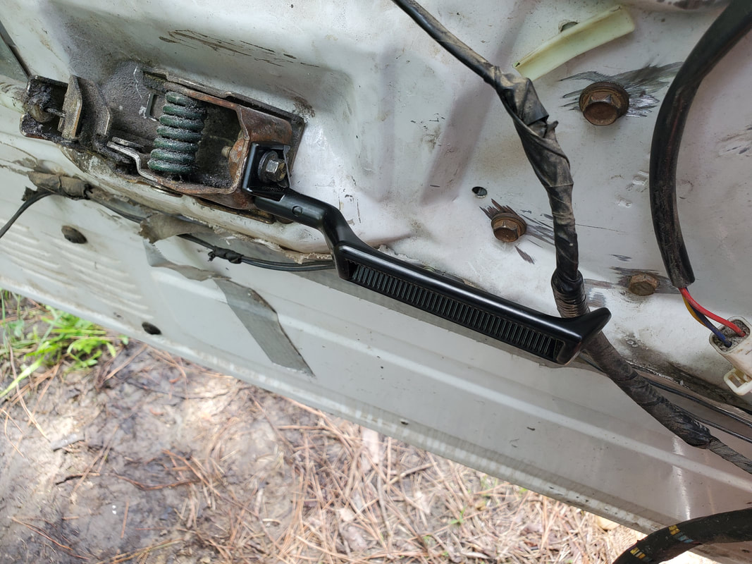
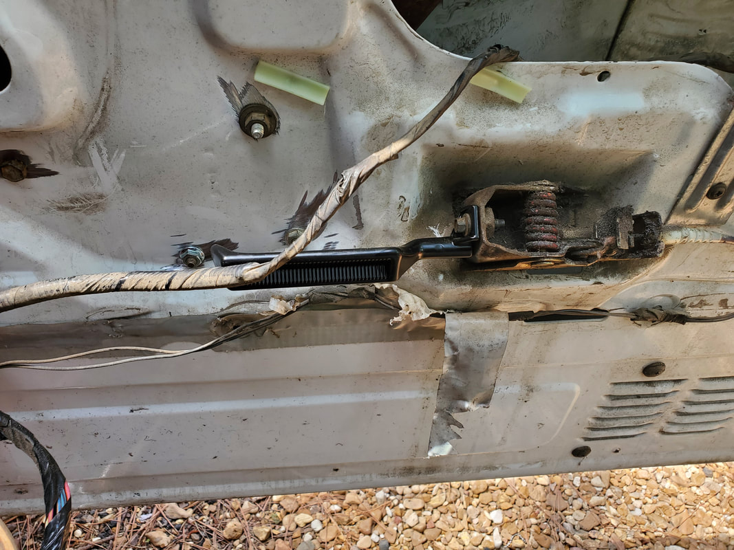
At this point I made my way inside the truck. I removed the door panel so I could access the hardware in the door, starting with the door handle. After looking at the mechanism for the lever, I seen that everything was still hooked up despite it not releasing the latch. After doing a little test it turned out that the cable wasn't pulling enough to pop the latch. I also found that the lever mechanism was moving some, which if I could solve that problem then the cable would have the extra pull necessary to release the latch.
After removing the lever mechanism I found that the mounting surface where the bolt went through was actually cracked, allowing the mechanism to pull free some and move like it did. I had to straighten out the bent out metal around the bolt hole then remove the threaded clip in the hole and replace it with a nut and fender washer underneath the bolt hole so everything when tightened up would hold against the damaged mount of the door frame and not move. After doing this, the lever was able to release the latch, finally.
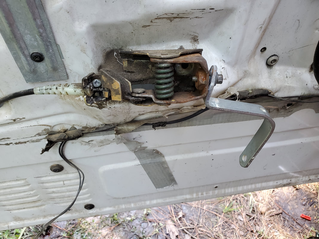
Door lever mechanism secured in place with nut and fender washer underneath to hold everything solid.
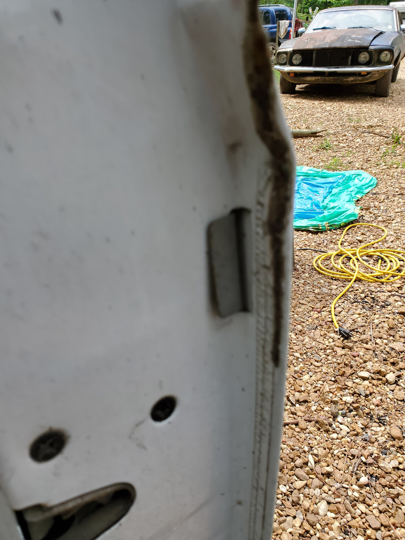
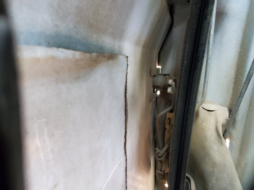
The next order of business was the window regulator. The window was able to slide up and down with minimum effort but still have resistance. I did take time to charge up a battery and hook it up. Now going on a tangent, on the ignition switch was in the on position with the key removed, as is common with these trucks. I was able to switch the key on to put power on the door windows. After trying the window, I found that the regulator had stripped gears inside. The motor would run but you could hear the grinding of the plastic gears inside the gearbox. I had to remove the regulator. Problem is, Ford in their infinite wisdom, took time to use rivets to attach the regulator mechanism to the door. I had to grind the damned rivet heads off to free the regulator.
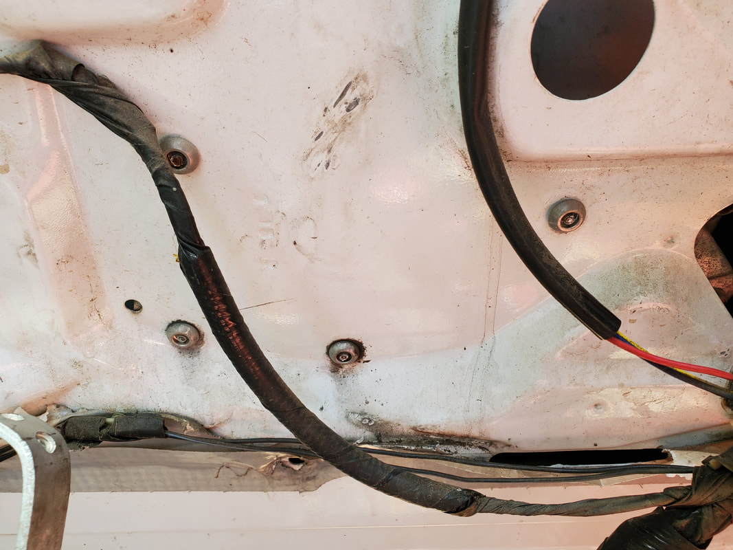
Rivets used to hold window regulator in place in the door shell.
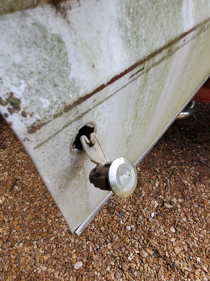
After grinding the rivets out I pulled the window regulator free but had to use a 2x4 to prop up the window so it would stay up, can't have rain getting inside the truck mucking up anything. Now, I will go back to the ignition switch. Thinking that the switch was just broken, I turned the switch to the off position with the outer knob piece spinning freely as it did.
This is where the fun part began. Since these switches have this flaw, you can still lock the switch if you return it to the off position, and it will stay there. This one did exactly that. It wasn't broken, just had the flaw where it'll release the key in the on position. And I didn't have the regular key. And the key for the F250 wouldn't work. So now the switch is stuck in the off position. And the steering wheel locked. This cylinder assembly would have to come out by hook or crook.
There is a locking peg that holds the cylinder in but will only release when the key is in the first position. That won't happen without the key. So out came the tools. For the next hour I drilled at the peg and pounded a center punch into the thing. I pried into cylinder breaking pieces off the cylinder body, allowing me to move and manipulate the assembly more, with the hope of being able to get that locking peg clear of the housing so I could pull the cylinder free. After enough working and beating and working and beating some more I was finally able to get the mangled cylinder assembly removed from the housing in the steering column.
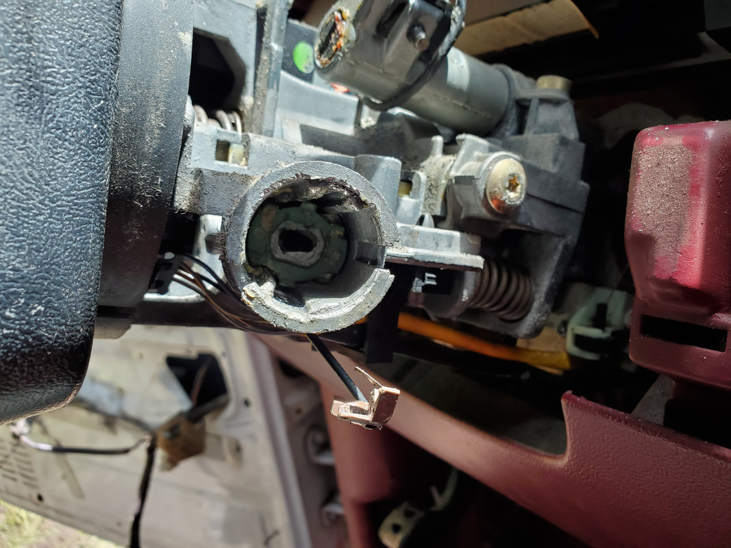
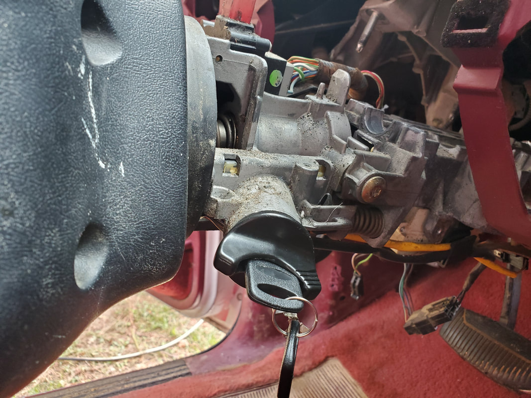
Opening where ignition cylinder went, showing gear mechanism that works lever to turn switches on within the column.
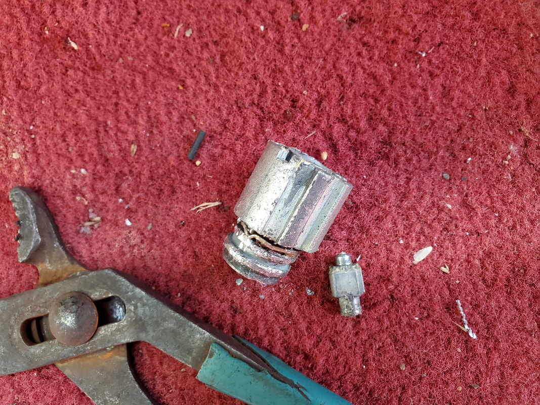
Remnants of ignition cylinder after removing it from steering column.
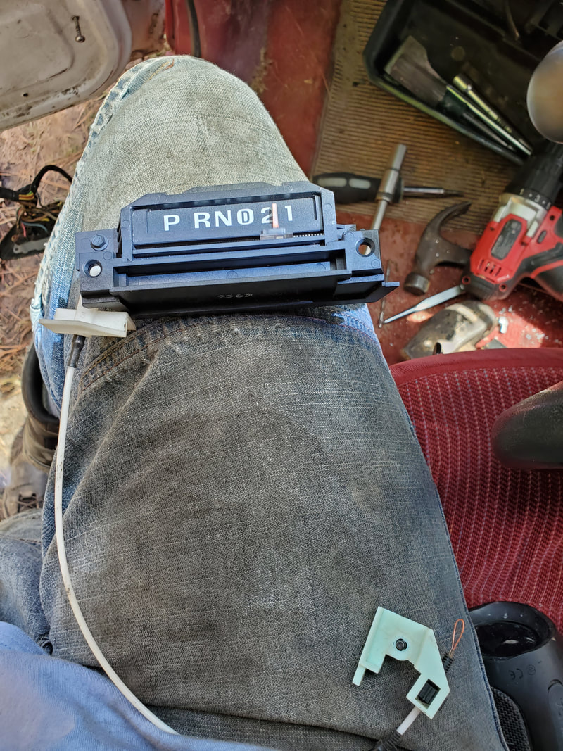
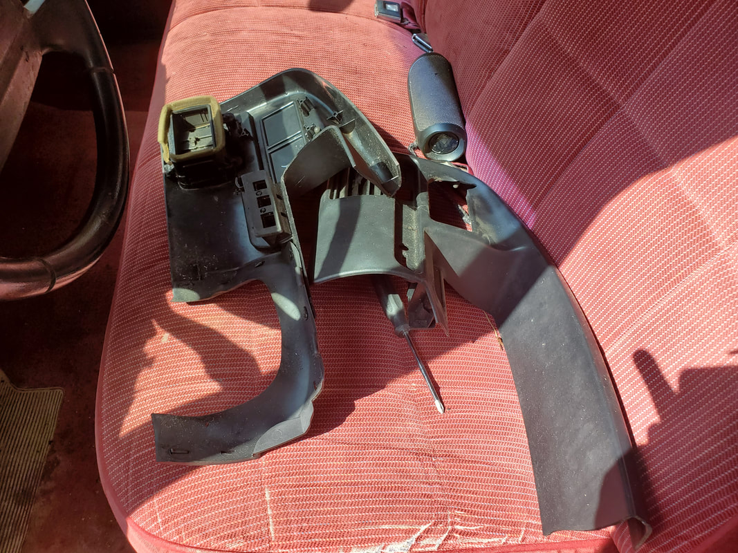
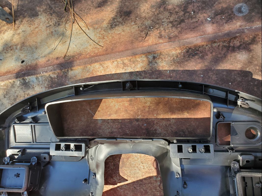
With the ignition switch taken care of I moved on to the gauge cluster and the shifter. I removed the molding covers from around the gauge cluster. That plastic piece will need to be replaced since it was in a couple of pieces. I ended up having to drop the steering column in order to have access to the top of the unit to remove the clips holding the shifter in place as well as open up the space to pull the gauge cluster free.
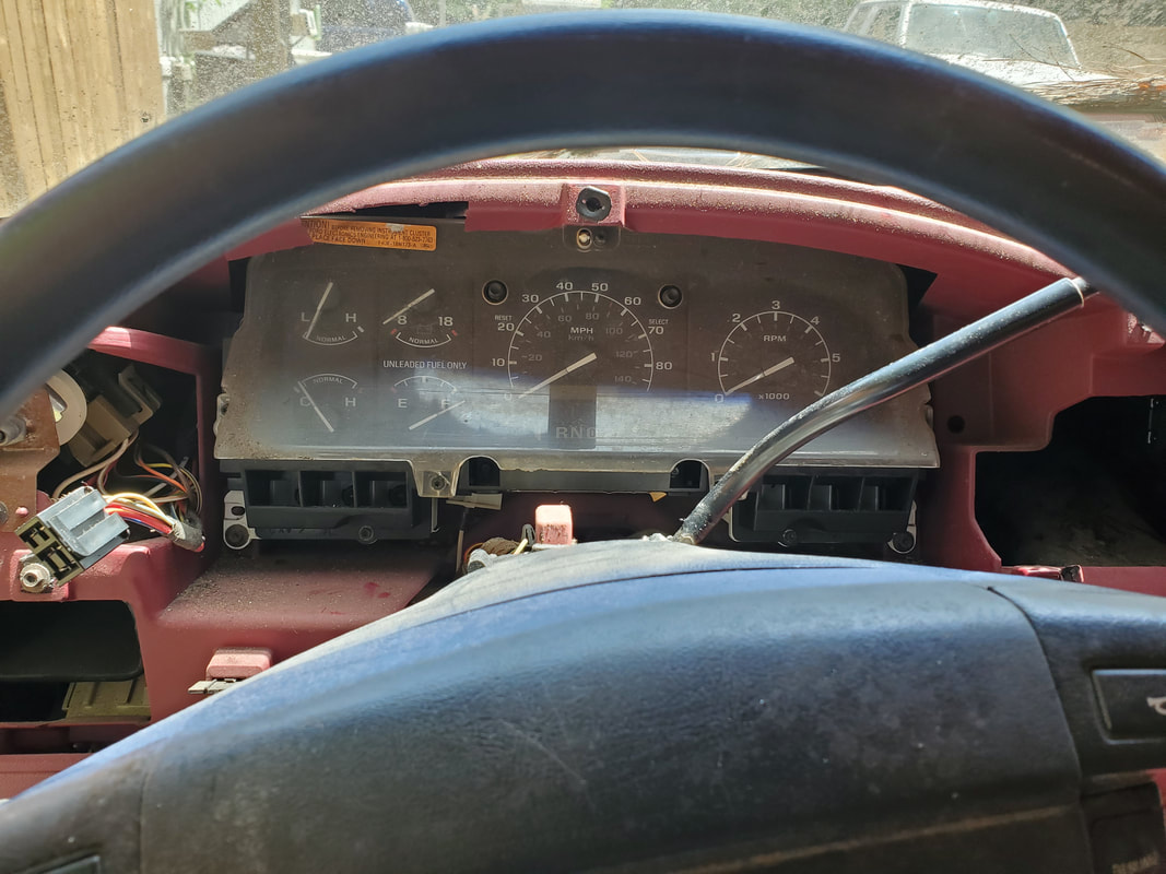
Gauge cluster after removing dash cover panel exposing everything. Note covers have been removed over steering column as well.
After pulling the gauge cluster out, I had to disconnect the little cable that attached to the shifter and linked up to the indicator in the gauge cluster. At the same time I removed the retaining clips that held the shifter handle in place, After popping the cable free from the shifter handle and removing the indicator from the gauge cluster (which was held in with a couple of screws), I was able to free all of these unneeded things from the truck.
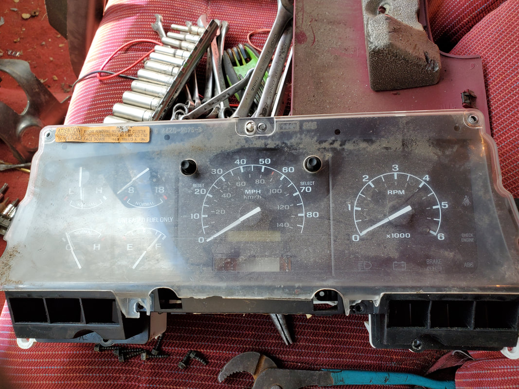
Gauge cluster with gear indicator removed from underneath.
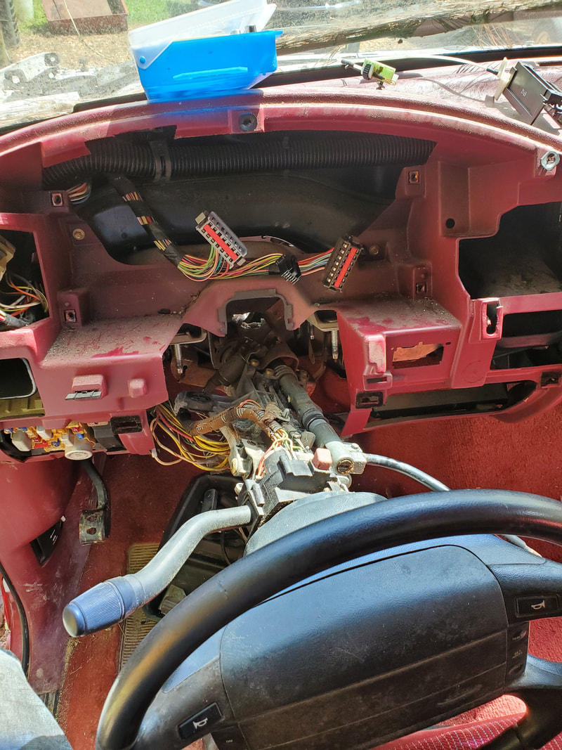
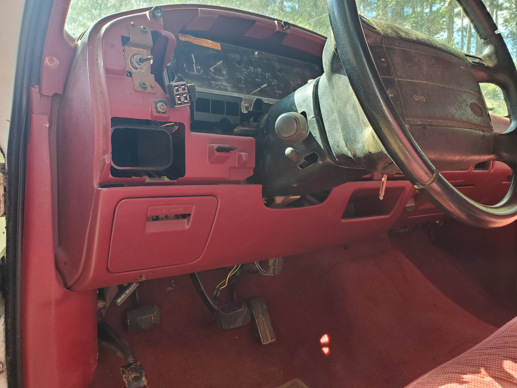
Steering column dropped to expose shifter handle prior to removal.
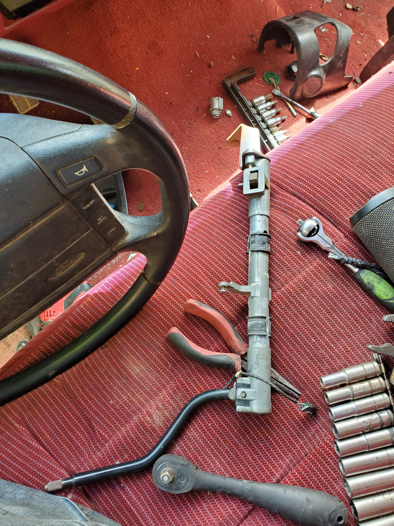
Shifter handle removed from steering column.
Indicator removed from gauge cluster.
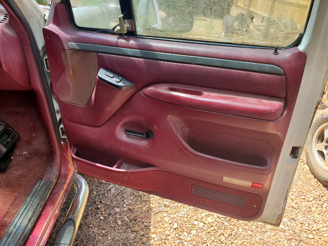
The last order of business was the passenger side door. Since the interior lever was alredy broken off there was no need to worry about that, I'll have to buy another one of those just like the driver's side. After pulling the door panel free I tried to work the regulator and had no action. I metered the lines going to the regulator motor and had power on them when I cycled the switches, so that pretty much told me what I needed to know, the regulator was dead. Just like with the driver's side, I had to grind out the rivets to remove the assembly, as well as propping up the window with a board.
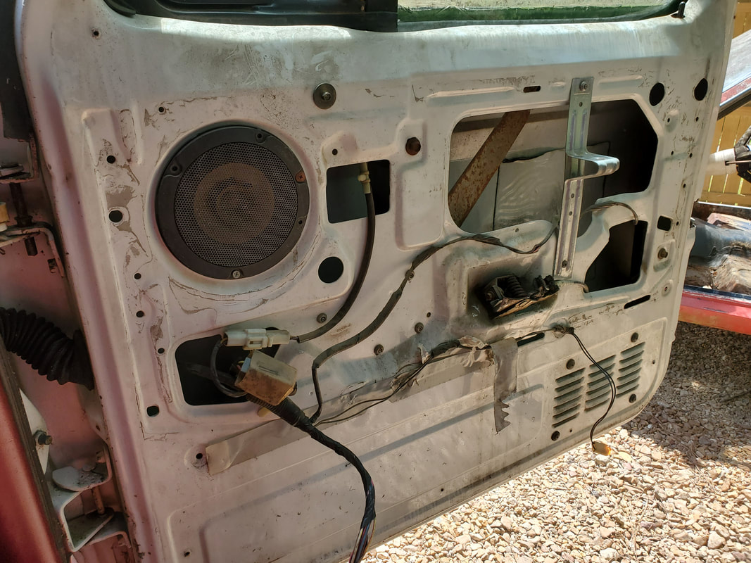
Passenger side door with same dilemma as with the driver's door.
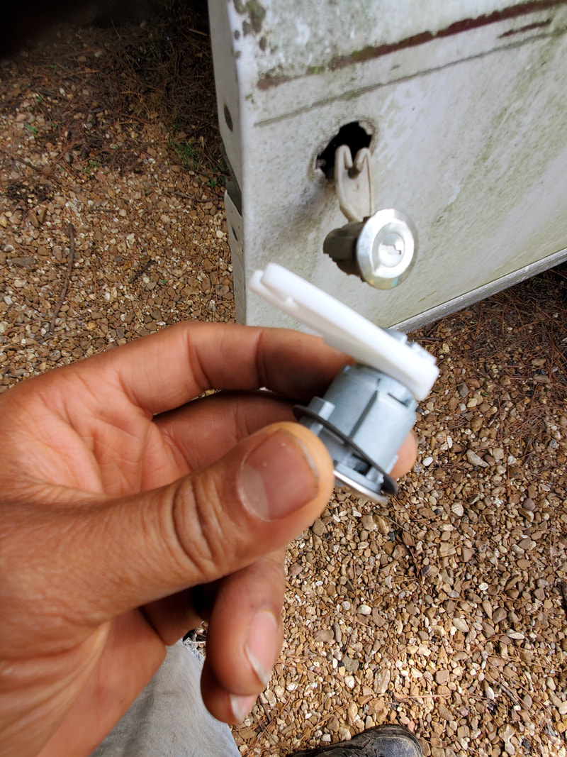
I managed to get the pair of door locks for the FMT in the mail so the first thing I did today was install those. It turned out to be way easier than one would expect. The lock mechanism is held in by a U-shaped clip and snaps to a linkage that hooks to the rest of the lock mechanism. Funny thing when I went to open the doors I found out the damned things were both locked! Luckily the vent window was open on one door so I was able to open the door. But anyway, I went ahead and worked the passenger side door, pulling the clip out.
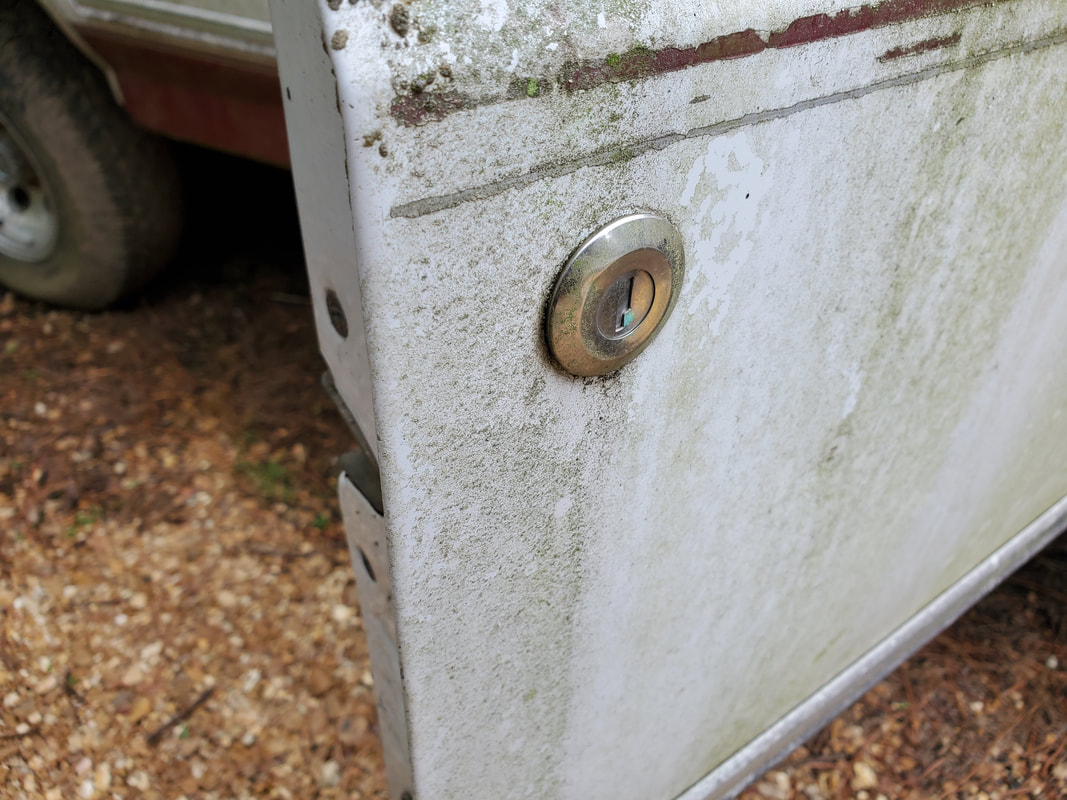
Old door lock cylinder in place.
Retaining clip holding door lock cylinder in place.
After pulling the clip, I worked the lock mechanism out, snapping it free of the linkage rod. Quick. From there I took the new lock and put the gasket on the piece and worked it in the hole in the door then snapped the linkage on from the inside since it was easier to do things this way. From there I snapped in the clip to finish things up. I tested the lock successfully, then moved on to do the same on the driver's door.
Old door lock cylinder hanging out by linkage to lock mechanism.
New lock cylinder with gasket ready for mounting.
New lock cylinder in place with linkage hooked up as seen from inside the door.
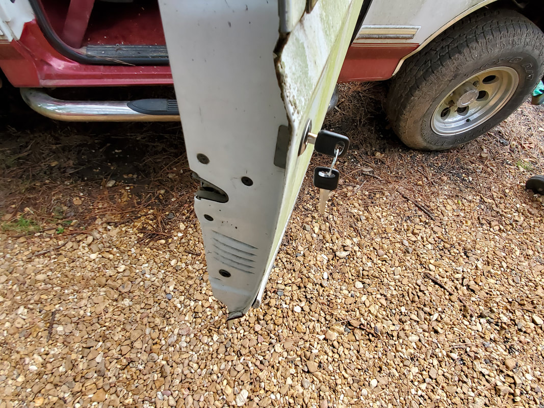
Testing keys in lock to verify functionality.
|
|
|
After finally receiving the replacement motors for the window regulators on the FMT, I set out to change the motors out on each unit. These motors are a straightforward swap out with nothing special like clocking the motors to coincide with the position of the regulator arms. The units are held in with three bolts each so that part of the process went pretty fast. But my biggest concern is reinstalling the units since they were riveted in, and whenever you encounter something that seemingly makes no sense, you have to look at it from the perspective of, "they did it for a reason". And there surely was a reason for this buffoonery.
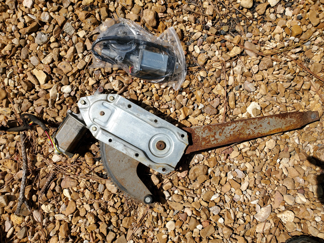
Old window regulator with new motor ready for swapping out.
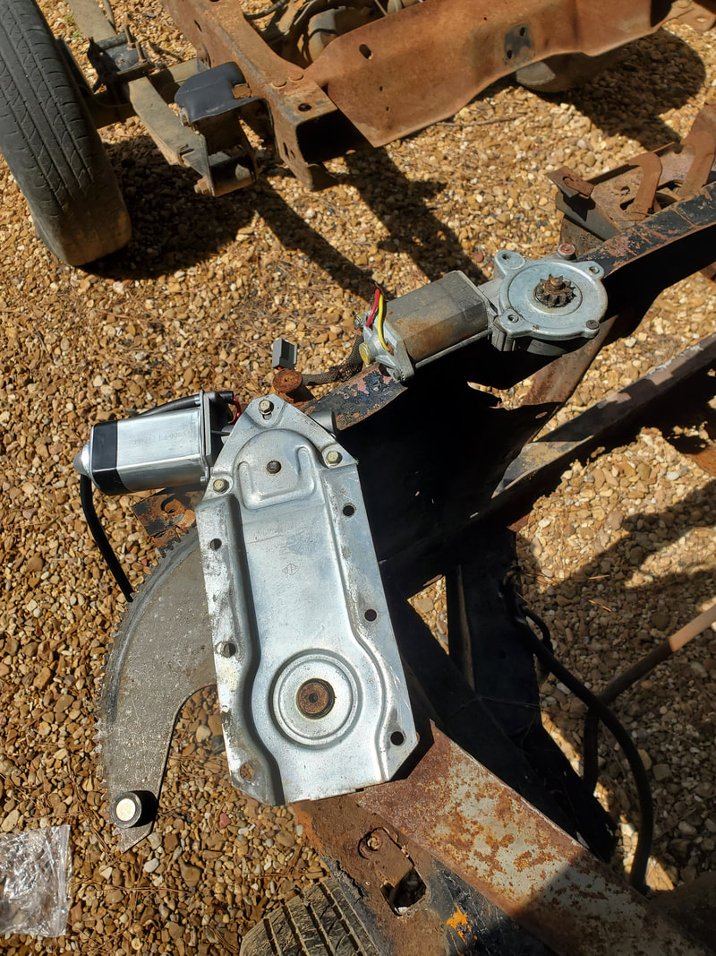
Window regulator with fresh motor installed and old motor set off to the side.
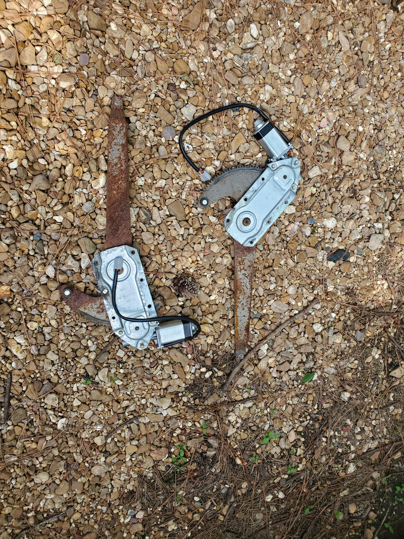
Both regulators with fresh motors installed and ready to go in their respective doors.
The reason for Ford riveting these units in place was because in their infinite wisdom they designed the components to have a tight tolerance. The mounting bracket portion of the regulator is mated real close to the moving gear of the regulator, meaning that I would have to move the regulator to expose the mounting holes in order to place the bolts through the mounting plate and into the door from the inside so the head of the bolt doesn't pass through the path of the moving gear. The nut would be placed on the outside onto the bolt. This of course provided its own challenges since we're talking about trying to put a wrench on the head of the bolt from the inside of the door where I couldn't see anything. I was able to get three of the four bolts on but had the hardest time getting the fourth bolt on because that one actually did require me to put a short bolt on from the outside and somehow hold the nut in place in the super tight space to get the nut threaded on.
After losing three nuts in the door and even losing the wrench in a spot of the door where stuff can fall in between the metal and be lost forever, I had to resort to one of those retractable magnetic wands for retrieving lost bolts. I was able to get the nuts back but the wrench is gone. I used the magnet to hold the nut in place while I put the bolt in, then had to use a flathead screwdriver to to wedge it on the nut to hold it in place while I tightened the bolt down.
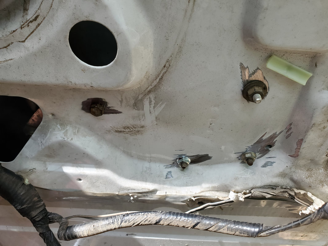
Regulator installed in door using four bolts.
Even with the four bolts in place I ended up having to spray some lubricant grease in the window tracks to slick things up since the window would bind at some points, a common thing with super old power window setups. After the oil worked its way down through both sides, the window moved up and down effortlessly. With that I put the door panel mount back up with a nut and bolt and moved on to the other door.
Door panel mounting bracket back in place with a nut and bolt.
As with the first door, I ran into the same issues with regard to placing the bolts through the regulator base and the door shell. After having to manipulate the regulator to get three bolts in and tightened down, after testing the unit for functionality I determined that the fourth bolt was not needed nor worth the headache to install. I then moved on to the other little, um inconsistency.
Window regulator installed in door using three out of four bolts to hold the unit in place.
Because the motors were exact duplicates and not side specific, the placement of one of the motors essentially had it in reverse of what a motor that was side specific should be. Even though everything bolted up properly (in reverse mind you), it had the system working in reverse. Now while I could've just left well enough alone, I felt it was stupid to have one window switch work in the right polarity and the other one work in reverse. I would have to pull the wires out of the plug and reverse them in order to have everything work in the right direction.
After trying to pop the female terminals from the plug end and damaging one of the terminals inside the plug, I just aborted that particular mission and took one of the old motors and cut the plug end off of it to use and snipped the terminal ends from the new motor.
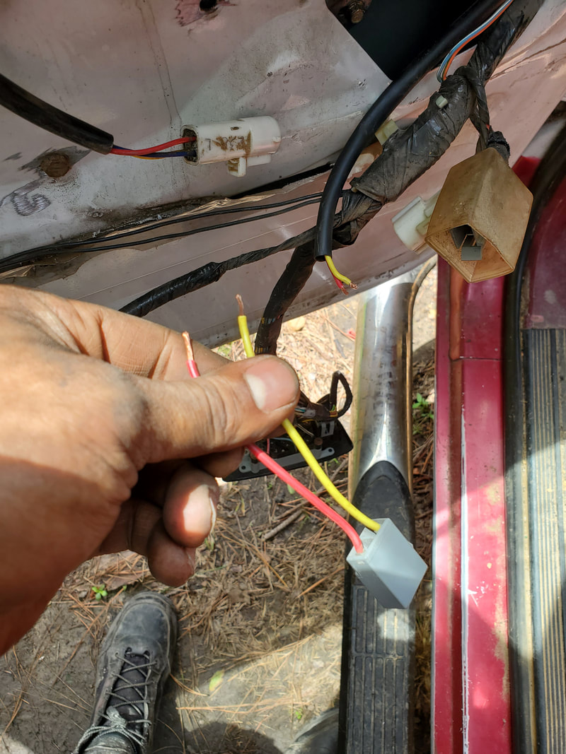
Wires from new regulator motor stripped and ready for splicing into replacement plug end.
Even though the wires were color coded, I still had to swap them around so as to achieve the polarity reversal of this motor. I used regular crimp couplings to connect the plug end to the wires from the new motor. After plugging everything back up I tested the window regulator successfully. As with the first side I lubricated the window tracks in order to allow the window to slide up and down effortlessly through the whole distance of travel. With that, I can move forward knowing the windows are now fixed on the FMT.
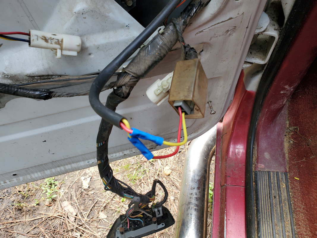
Replacement plug end spliced into new motor's wiring.
|
|
|
|
|
|
I did receive the door handles finally and they were the last thing I needed to get the doors back together. These components really didn't take any effort to put on as they're held on by a single bolt for either handle. This obviously went quickly. I am glad to have gotten the metal ones because the plastic ones require you to kinda be easy on them since they will break pretty easy.
Driver's side door handle installed.
Passenger side door handle installed.
Installing the door panels was pretty easy as well as these components are a single piece that just snaps on. After working the door handle through the hole and the lock knob through its hole the panel I was able to mate the panels up to their respective doors. Since these are old panels, most of the time people will have put screws through spots in the panels to help hold them in place. The plastic pegs typically used for these panels are either worn out or missing or even the mounts for the pegs are broken on the door panel and rather than replace an entire door panel people will just install screws through spots near the corners, typically out of the way where they won't be noticeable to anyone who isn't really looking for them. These panels are no different as they had some pegs to help hold them in but there were a couple extra screws in the bottom corners that held them on. I went ahead and reinstalled these components to get the panels solidly mated to the doors then verified the opening of the doors to make sure the handle and latch mechanisms were working properly.
Driver's side door panel installed back on door.
Passenger side door panel installed back on door.
|
|
|
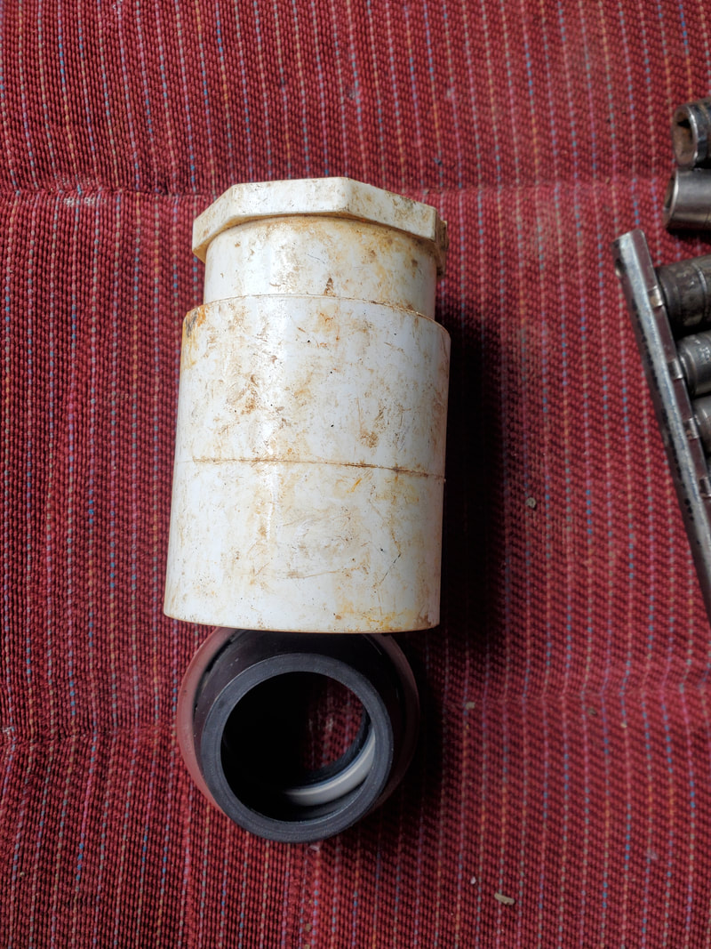
One of the next things I focused on was setting up the fuel system on the truck. The first thing I did was get a donor fuel pump/sending unit from the junk yard and take it apart, removing the fuel pump motor. My plan was to install a small piece of hose to connect the output nipple with the strainer nipple in the housing but after breaking this, I just removed the strainer and installed a long enough hose from the output nipple to extend out of the bottom of the housing. After reinstalling the sending unit assembly along with the vent tube (borrowed from the other fuel tank), I put the tank up, hooking up the fuel filler tube and sending unit cable and a short length of rubber hose between the output nipple and main fuel line. Two straps hold the fuel tank in place, hooked to the frame on one end and a single nut and bolt on the other end. With the fuel tank installed and hooked up, the truck's fuel system is pretty much complete.
Front fuel tank prior to installing modified sending unit. Tank would have to be vacuumed out due to rust dust being in place inside the tank.
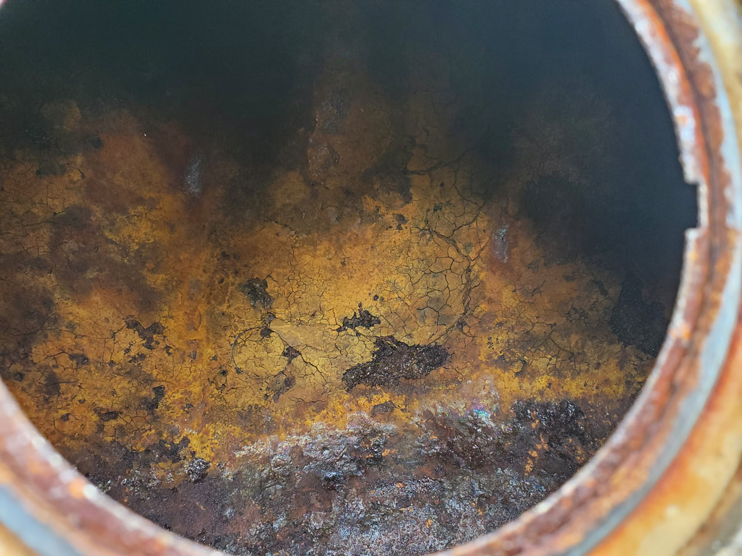
Even after vacuuming out rust dust, this crust inside the tank may be a problem if it gets sucked into the fuel line due to there being no strainer in place. A fuel filter will have to be installed before the pump to help keep this from being a serious problem.
Modified sending unit assembly, after removing fuel pump from inside housing. Note hose protruding from bottom of housing where strainer used to be.
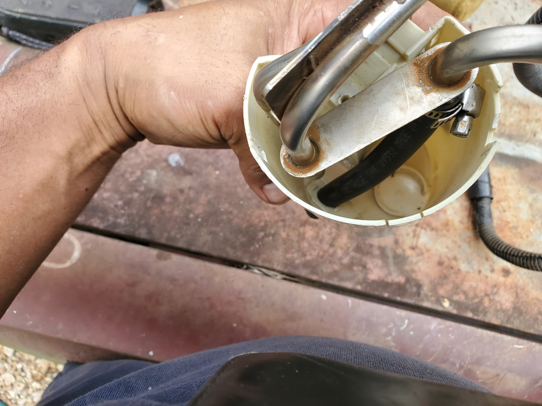
Inside of fuel pump housing showing how hose is connected to output nipple and routed down through bottom of housing.
Fuel tank staged by truck with sending unit and vent tube installed. Note how vent tube is cut short and plugged with a bolt as it's not needed, the hole just needed to be plugged up.
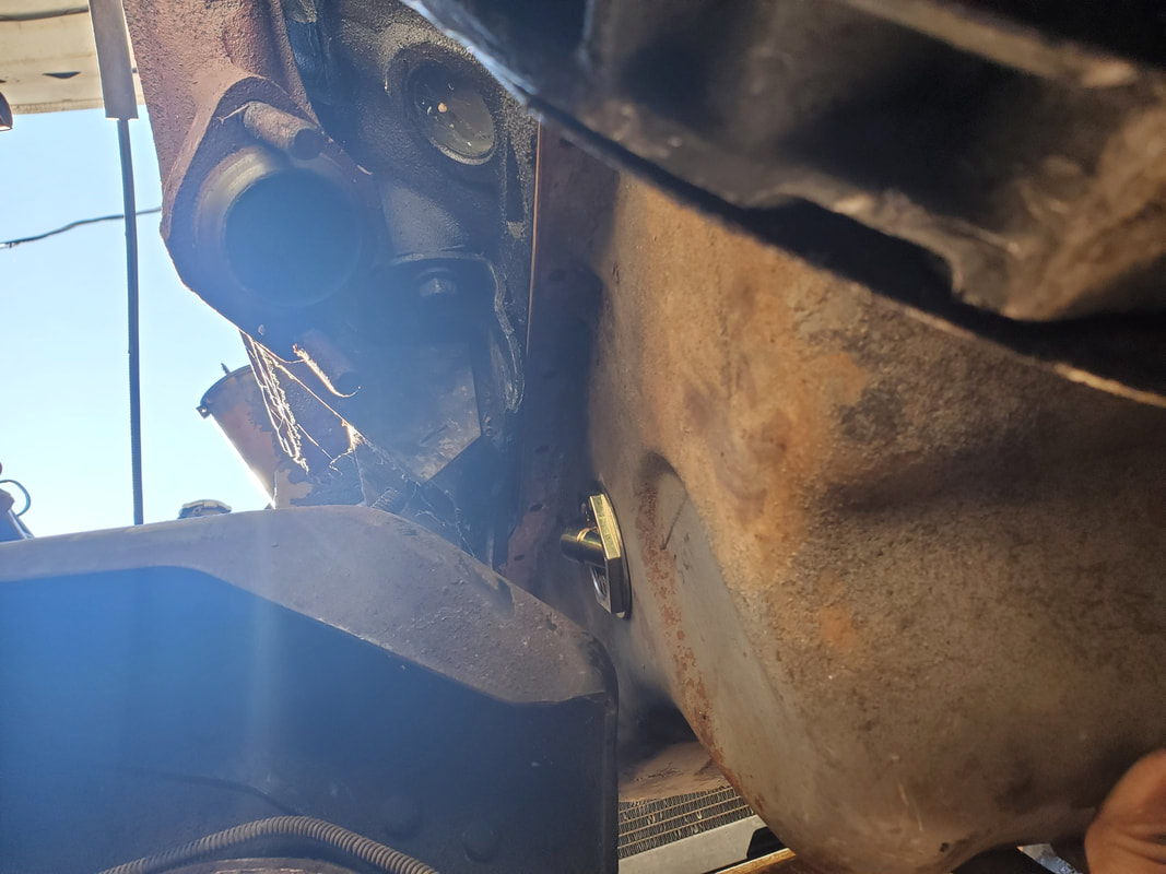
Fuel tank installed under truck. Everything is hooked up, fuel filler tube, sending unit plug, output nipple is hooked up to main fuel line via short piece of rubber hose. Note straps in place holding tank up.
Continuing on with the work I installed the ignition key cylinder. This was pretty straightforward, just getting everything lined up as far as position of the internal switch gear and the cylinder so the whole unit would go into the hole on the steering column. With the ignition cylinder in place I moved on to the clutch/brake pedal assembly. This was a little more involved as the clutch pedal assembly was larger than the regular brake pedal assembly that had to come out first. The steering column had to be fully disconnected in order to move it out of the way to clear space for the installation of the pedal assembly. Once installed I was able to reassemble everything back as it was.
Ignition key cylinder installed in steering column.
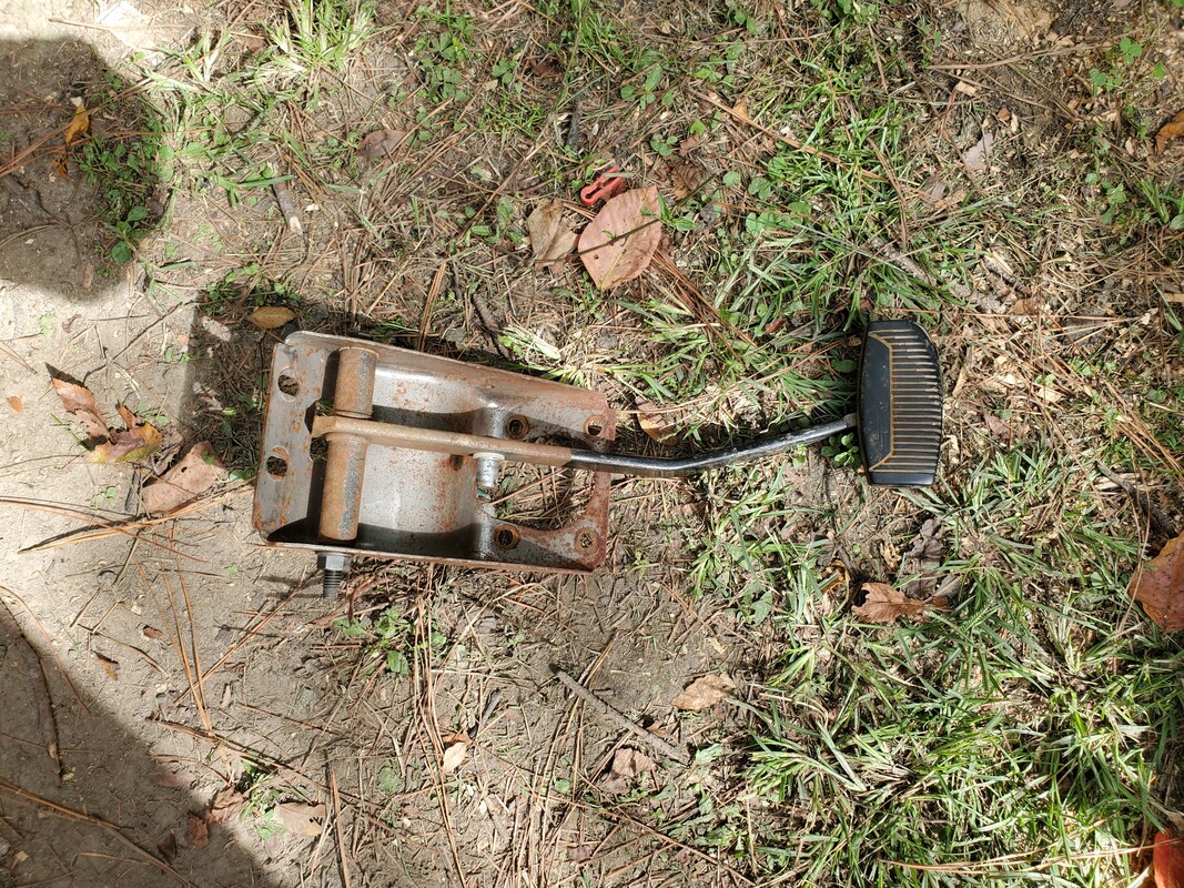
Old brake pedal assembly removed from truck.
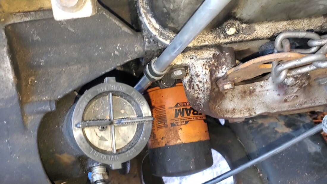
Brake booster removed from its mounting space. The four studs on the brake booster also help hold the pedal assembly in place along with a couple of other mounting points, two of which are the mount for the clutch master cylinder.
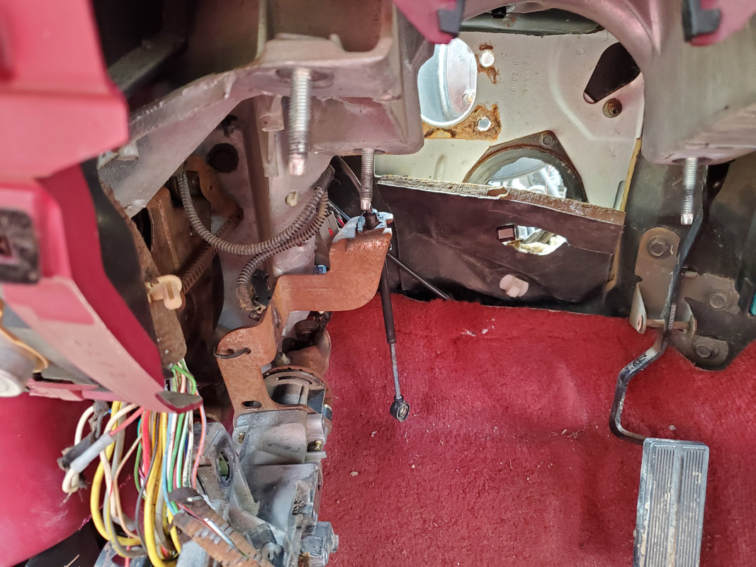
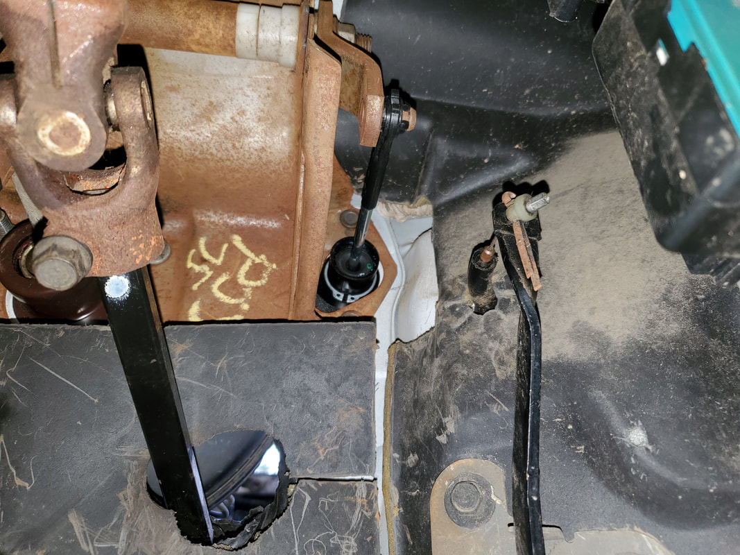
Under the dash area showing steering column disconnected and off to the side.
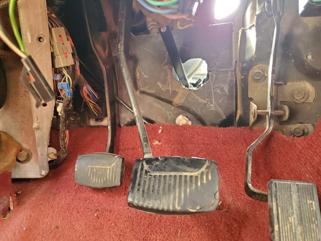
Clutch/brake pedal assembly installed in place of the old brake pedal assembly. Steering column is back in place as well Brake master cylinder rod is hooked back up to brake pedal along with brake light switch.
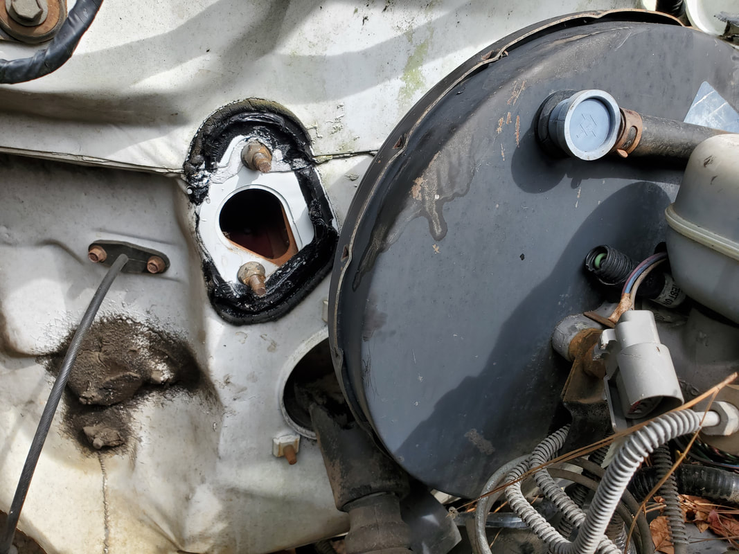
Clutch master cylinder mounting point, uncovered by removing a cover that was installed from the factory for this once automatic transmission truck.
I had to figure out the wiring for the gauges on the truck next. Since the old EEC system will no longer be used, all of the old wiring harness was removed from the main plug on the fender panel where it connects the engine wiring to the plug going to the cab. I had to do some research to see what the wiring color codes were for the oil pressure, temperature, and tach signal/coil wires. After combing a couple of forums, I got the info I needed to go to the cab side plug and the engine wire harness to match up the wires from the harness to the wires going into the cab. From there I was able to cut those wires from the plug going to the cab and pull them free from that wire bundle so they can be spliced later. I then disassembled the engine wire harness to pull the individual wires for the coil and temp/oil sensors. From there I spliced the wires to the cut wires, soldering the ends together and covering the solder joints with heat shrink tubing to protect the solder joints. I used electrical tape to wrap the coil wires together into its own bundle and the oil/temp sensor wires into their own bundle. The only other thing I had to worry about was the alternator but the wiring for that is separate from this main wire bundle, being connected to the battery and the main wiring of the truck. Even the ammeter is hooked into the accessory line to monitor the voltage to determine whether the alternator is putting out the 14+v for charging or whether the battery is discharging and showing below 12v, pretty simple circuit. With the gauges and other electrical loads figured out on the truck I can reassemble the dash/gauge panel and focus on getting the powertrain assembled and installed.
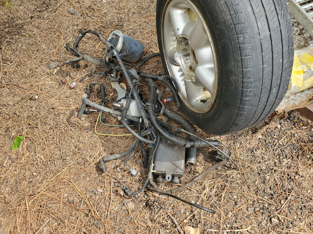
Engine wiring harness pulled from truck that will be the donor for the wires/plugs that will be spliced in to the cut wires for the oil pressure, temp, and coil/tach lines.
Wires cut from cab side plug. These wires feed the temp and oil pressure sensors and the coil power and two tach signal lines.
Oil and temp sensor wires cut from engine harness. Note the round style female plugs on the ends of the wires to snap onto the stud ends of their respective sensors.
Coil plug and wire removed from engine wire harness. This plug has two wires, one for coil power and one for the tach signal, which branches into two separate wires, one for the gauge and the other (not sure) for a feedback to the ECM. Not sure which one is which so they're both getting hooked up just to be sure.
Oil and temp sensor wires spliced into the wires that were cut from the cab side plug. Note heat shrink tubing over solder joints.
Coil wires spliced into the wires cut from the cab side plug. Again, there's three wires, one for coil power and the two are for the tach signal, both connect to the single wire coming from the coil. Both of these wires were traced back to the gauge panel, making it unclear which one is needed for feedback to the gauge itself so both wires will be hooked up just to be sure of functionality of the gauge.
Coil plug draped over fender while splicing ends in. Even though this is a Ford coil plug used on the higher powered coils that were used in the EEC system, that coil will not be used since we will be using the same hybrid HEI distributor like what we used in the Dodge. I will more than likely source an aftermarket HEI plug that will take the place of this plug, allowing for a more professional/factory plug in to the coil power and tach signal lines versus using individual female terminals on the ends of the wires.
Coil wires bundled up and oil/temp sensor wires bundled up, wrapped in electrical tape to neaten things up. Once the engine is in, these wire bundles will be routed properly and possibly zip tied in place to keep things neat.
With the engine accessory wiring figured out I was able to turn my attention to the interior, finally being able to reassemble the gauge cluster and greater dash. Only problem with the dash is the idea that the dash panel that snaps around the top portion of the dashboard and gauge cluster is broken into three pieces with the smaller piece missing. Luckily I was able to source a replacement panel for a reasonable price so the first chance I get I'll be getting that piece in order to complete the dash reassembly. Once the panel is on I'll also be able to put the headlight knob back on as well. I also bolted the steering column back up along with the cover pieces for it and the lower dash panel, leaving just that broken upper dash panel.
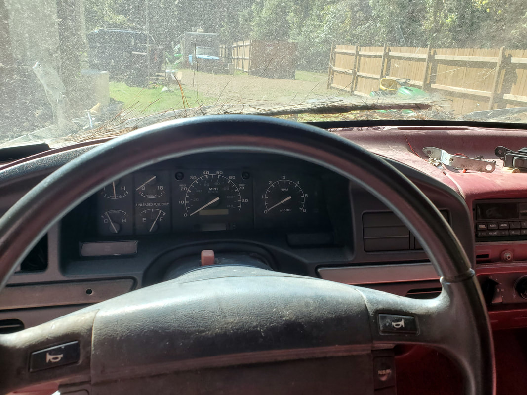
The gauge cluster installed in the dash frame. Note all the gauges in the cluster, pushing the reason for wanting the factory gauges operational.
Lower dash panel snapped back in place. Coarse thread screws hold the lower portion of the panel in place in the frame. Note plastic covers over steering column.
Broken dash panel, there is no repairing this. Once this is replaced, I can reinstall the headlight knob and finally get the interior written off. Other than some small accent pieces, there's nothing let to do in the interior.
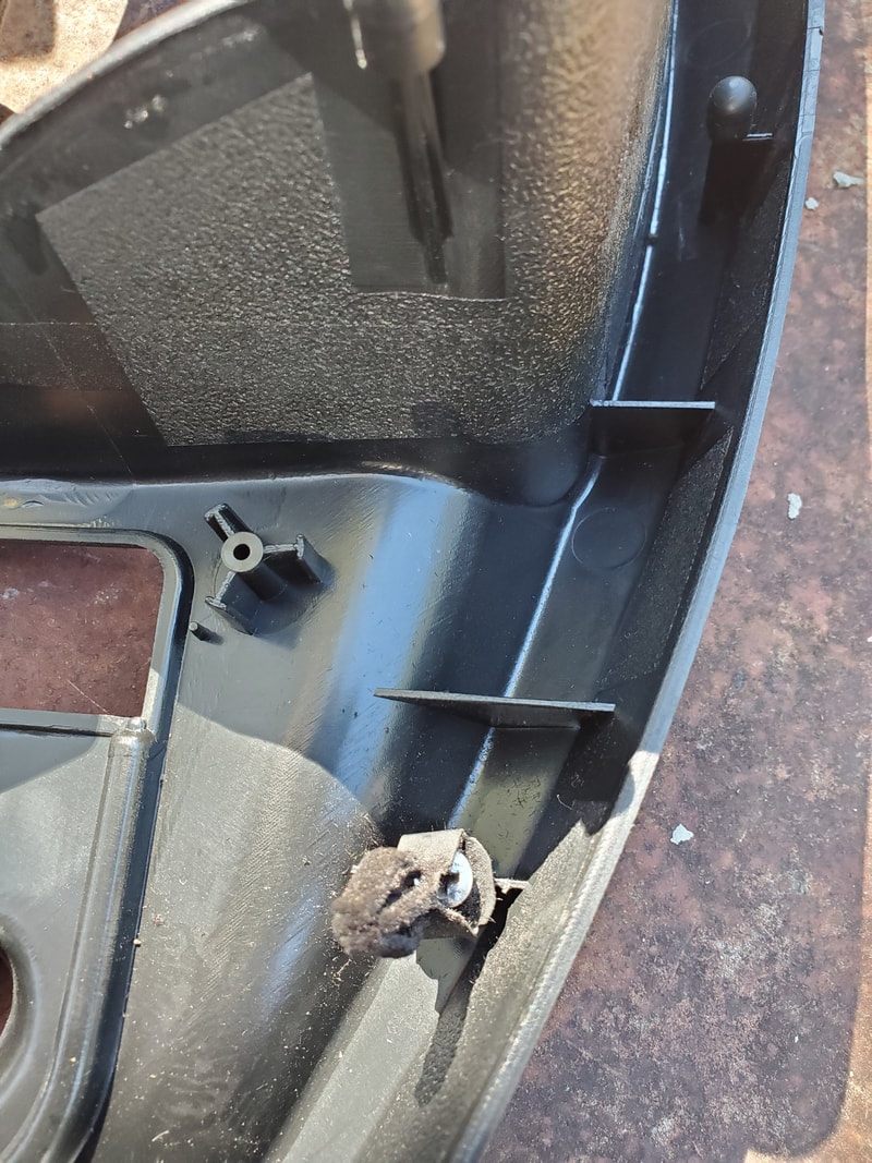
Closeup of the clip secured to base on the back of the dash panel to secure the panel to the dash frame. These clips appear to have originally been heated to mushroom the plastic base to make the plastic melt around the hole in the bottom of the clip. Instead I threaded a small sheet metal screw through the hole in the bottom of the clip and screwed it in with the clip at an angle to allow for the screw to go all the way into the base to hold the clip in place.
Shot of the three clips that are present along the top of the back of the dash panel. One clip was able to be secured via a screw completely while the other two have just a little play due to the screwdriver being unable to fully connect with the screw to ensure proper tightening once the clip was close to being fully mounted.
Shot of dash panel installed on dash frame, as appears from the door. One screw near the left bottom had to be removed prior to securing the dash panel. Since the screw used a torx driver, it was replaced with a Phillips screw to hold the dash to the frame. The screw is hidden by a piece of molding.
Shot of dash panel as it appears from driver's seat. Note two molding pieces on either side of the steering column. After carefully mounting panel by making sure the three clips were lined up and snapped in place, the Phillips screw was installed to secure the panel. The two molding pieces were snapped in place in their respective spots, one being over the Phillips screw. Lastly the headlight switch knob was snapped in place to complete the install.
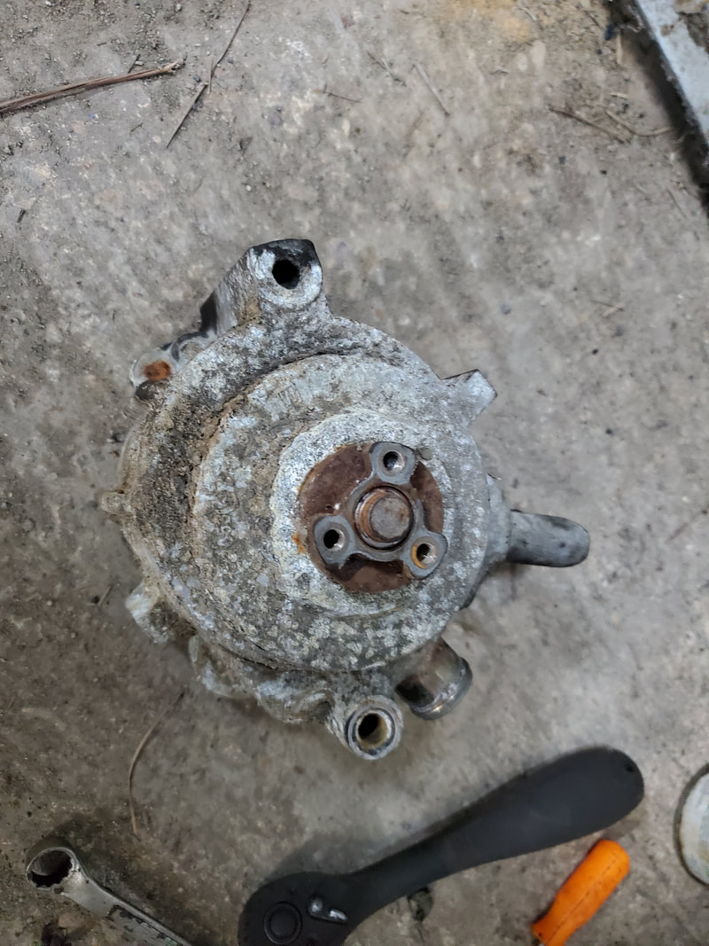
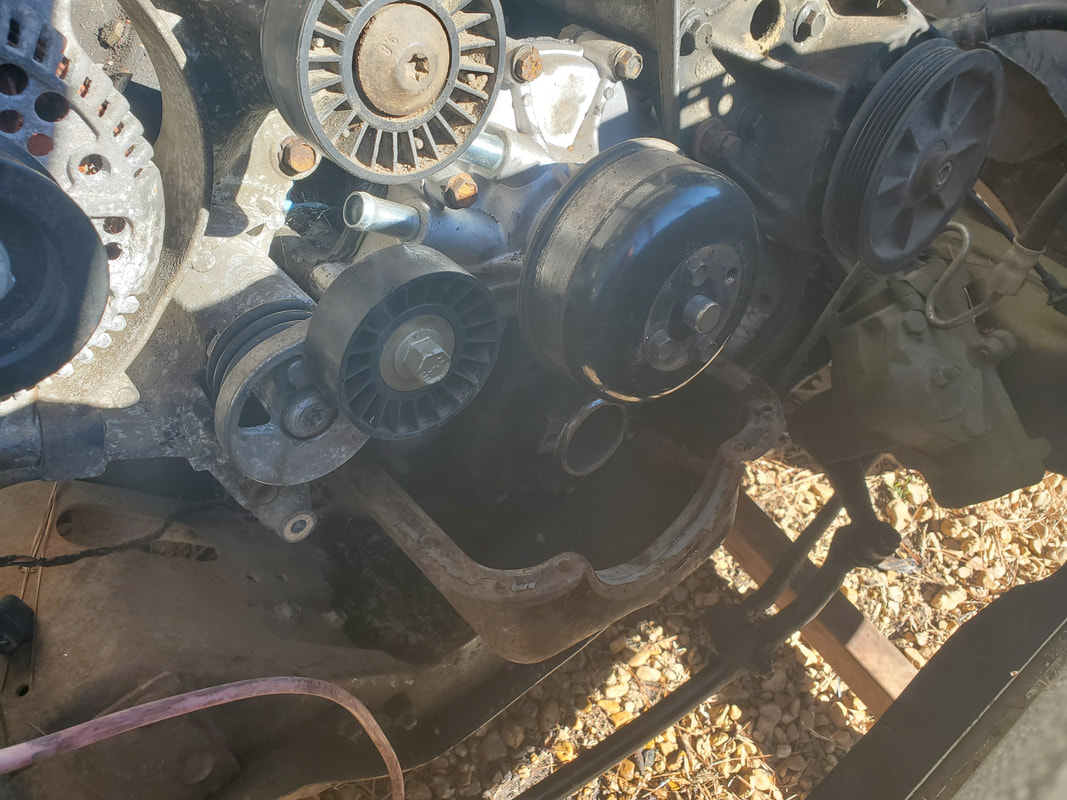
At this point I turned my attention to the engine itself, since there really wasn't much to do on the body of the truck. I still had to get the components pulled from the engine that wouldn't be used in the new configuration then install those components that will go with the newer configuration that would've been used in this truck. I had to get another accessory bracket as well as a harmonic balancer and pulley for this year engine since it will have everything hooked back up accessory-wise. As for the fuel system I planned on removing the 2bbl intake and replacing it with a 4bbl unit and dropping one of our Edelbrocks on top. After pulling a bunch of old hardware from the engine, I found I had to ditch a lot of stuff that wasn't compatible with the newer configuration. I had to change the water pump, balancer and pulley, even the timing cover. Obviously the brackets for the alternator and power steering pump had to be changed out. This engine didn't have AC on it so the newer bracket will accommodate the AC compressor along with the newer power steering pump and alternator. Little by little I'm getting this engine together and ready.
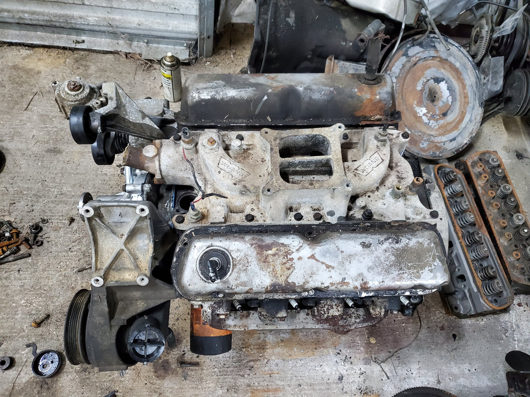
Instead of trying to buy a whole other 4bbl intake I figured I could "borrow" the intake from the 65 Mustang's engine since the engine is on the ground in the garage. The intake will fit right on the 302 and allow me to get this engine close to readiness while not hindering me in another field.
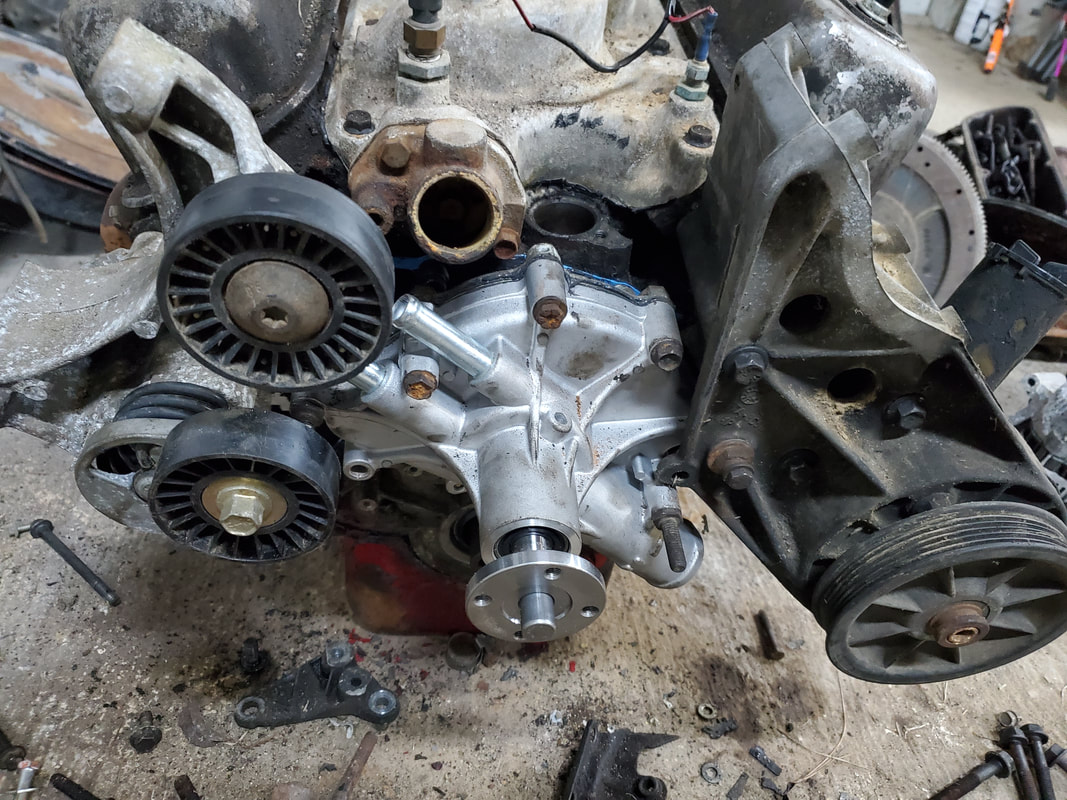
As stated I had to replace a lot of the old components. The timing cover had to be changed out due to the manual fuel pump port interfering with the power steering pump bracket plus the base for the water pump not matching. I had to replace the water pump since a lower profile pump was used on the 94 engine. With the new timing cover on I was able to mount the water pump, along with the two different brackets. I actually had the old 94 timing cover still along with the bracket that holds the smog pump and alternator. I had to hunt down the right sized bolts from the salvaged bolts from this truck I had plus my own stock before I could get the whole works fully assembled.
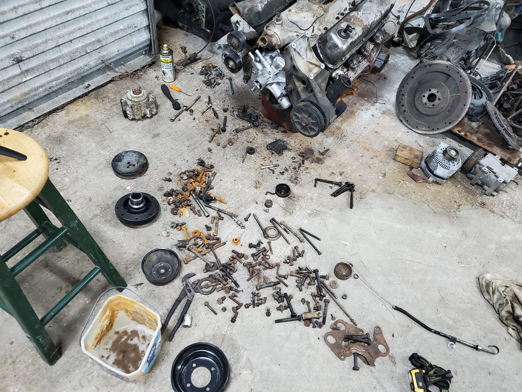
neous bolts scattered in the search for the right sized bolts to hold the timing cover and the two accessory brackets in place.
The smog pump on the right side bracket was frozen. I ended up having to remove this since I can't even use this as a pulley bracket to allow the serpentine belt to be driven properly. I'll have to see if there's any kind of bypass where I can put a bracket with the pulley on it to simulate the smog pump or just re-route a shorter serpentine belt to take advantage of the fact the smog pump isn't there
With the few remaining components left to install on the engine, the alternator, AC compressor, all that was left was installing the slave cylinder and throw-out bearing on the transmission, prior to mounting to the back of the engine. With those components installed, I had to prep the engine to be lifted by the engine crane so I can get it in the right position to make it easier to mount the transmission onto the engine. I did have to ream out the mounting holes on the transmission bellhousing since the engine this tranny went on used 14mm bolts, the older engine used 5/8" bolts. After getting that out of the way, I was able to get the transmission mounted and the bolts secured. With everything slid together, I did a test and rotated the crank some to verify the transmission's output shaft also turned, which it did. With the two components mated together, i lifted and moved the powertrain to a staging spot in front of the garage door. At first I contemplated bringing the truck up to the garage to install the units, but I decided to just go old school and drop the powertrain in the back of the F250 and bring it down to the site of the FMT, along with the crane, and stage the work area, like I used to, and just have the crane stationary, with the F250 staged on the other side of the crane with a chain connected to the FMT in order to pull the truck as I work the powertrain into the FMT's engine bay. Once the assembly is in the truck, I'll install the transmission crossmember in order to cradle the tail of the transmission. If the engine mounts on the engine aren't compatible I can temporarily rest the engine on the K Member until I get the right mounts and assemble everything properly.
On a side note I will have to pull the oil pan off due to the idea that the bastard engine assembly is missing an oil dipstick. The newer timing cover has no oil dipstick, unlike the older timing cover. Since the old timing cover had the dipstick there was no provision on the block for a dipstick. On the newer engine the block has the dipstick. Since we have a no dipstick newer timing cover on an older no dipstick engine block, there is no provision for a dipstick anywhere. The solution: Install a pan mounted dipstick, similar to the kind used on a Powerstroke diesel engine. This will require removing the pan and drilling a hole with which to mount the dipstick flange before mounting the pan back in place to finish that little issue.
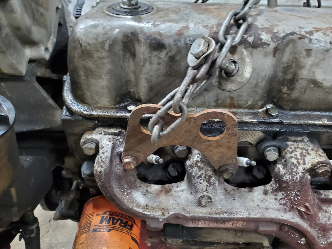
Hook plate attached to the right exhaust manifold to aid in hooking the crane's chains to the engine prior to lifting. Chain was hooked to this plate, and to one of the manifold bolts on the other side and to two bolt holes on the backs of both cylinder heads.
Engine hooked to the engine crane, ready for mounting of the transmission.
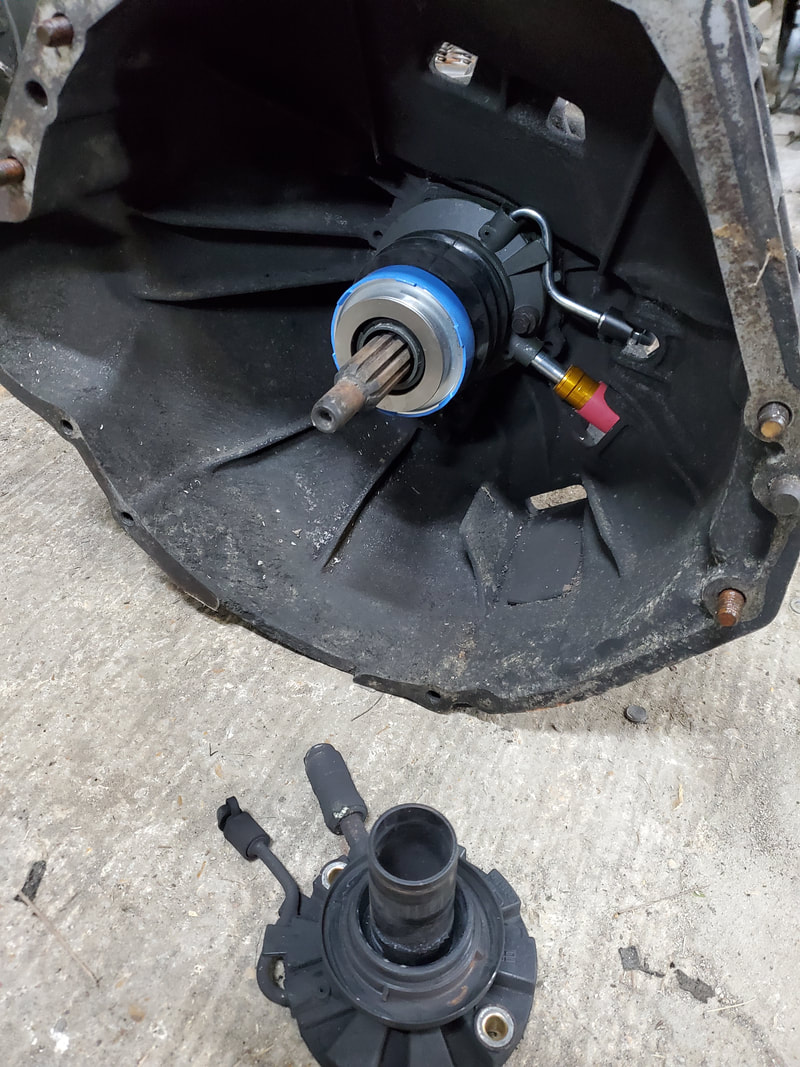
Clutch slave cylinder and throw-out bearing installed on transmission. Slave cylinder was held on by two 10mm bolts, fast install. Old slave cylinder is laying on floor in foreground.
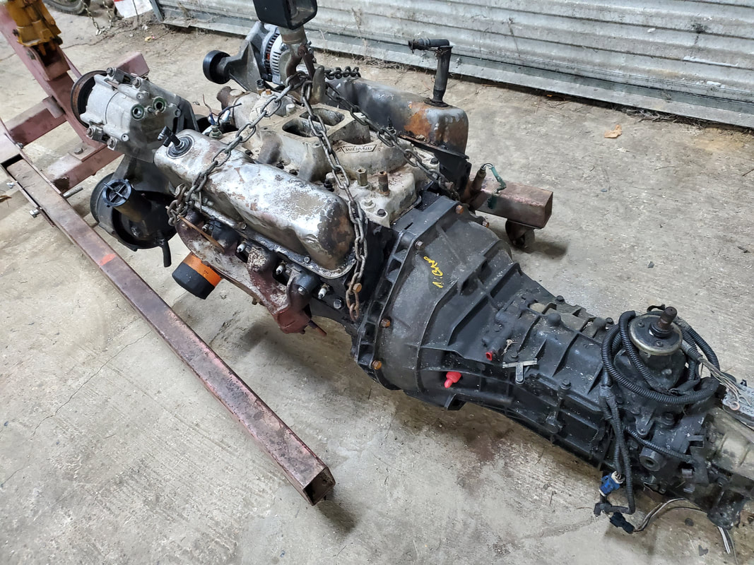
Transmission mounted to the back of engine, the powertrain is now together and ready for lifting up and out.
|
|
|
|
|
|
|
|
|
After getting the engine and transmission mated together it was finally time to install this shit in the truck. At first I planned for us to drag the truck up to the garage to install the powertrain but then decided against it. I chose to bring the powertrain and the crane down to the truck and do the install the old fashioned way, with the crane stationary and using another vehicle to drag the truck forward slightly as we work the engine and tranny into the engine bay. This worked out about as normal as it always had, being nerve wracking due to the fact that we have 1000bs of metal hanging high and in a position where any mishap will be a huge disaster. In the end it worked out pretty good and we ended up getting the rig in the engine bay. That's not the end of it however, since the oil pan needs to be replaced. Despite this engine coming from a truck, Ford changed up the sump position in their V8's later on in their trucks so the 94 year and similar trucks require a rear sump oil pan. This is only a minor setback as I can jack the engine back up with the crane to swap oil pans. It's also just as well since I have to install the oil pan mounted dipstick flange in the pan and that would be easier with the pan out. Another issue is the idea that the transmission crossmember doesn't quite fit right on this 5 spd, more than likely due to the idea that this tranny came from a 96 year truck and this being a 94, sometimes, slight differences can be present. Because of this, I was unable to use the secondary braces on the crossmember. I had to move the main crossmember back to the next set of holes to be able to secure it. I also need a tranny mount to secure the tail of the unit to the crossmember. Lastly I will have to change the slip yoke as its diameter is slightly larger than what is needed for this transmission. Luckily the driveshaft appears to be of the right length so getting a replacement yoke should not be that big of a deal compared to having to have a whole driveshaft made. I also took the time to install the clutch master cylinder and get it hooked up to the slave cylinder on the transmission and to the clutch pedal so at least that part of the system is all done as well, along with the hood.
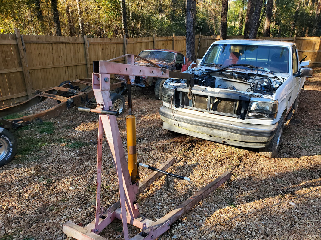
Engine crane staged in front of truck after dropping engine/transmission in. The crane was acing the other way to unload the powertrain from the F250. Once on the ground the crane was turned around to get it staged to lift and install the rig into the FMT. The F250 was used with a chain to pull the FMT forward as we worked the engine/tranny into the truck.
Engine in the engine bay, note angle engine sits due to oil pan resting right on K member.
Jack under tail of transmission to hold it up in preparation to install the crossmember.
Transmission crossmember installed with only one bolt on the left side due to unit being in at an angle. This transmission doesn't fit quite right with this crossmember.
Hood being installed. We had to bolt up both the standard hinge and a spring carrier to each side then adjust the hinge position to get the hood lined up properly so it will close evenly.
Hood closed evenly on truck's body. Only problem is the right front corner of the hood. It appears to be pushed in some where it will have to be straightened out some to make it sit flush with the front of the fender. More aesthetic than anything, this doesn't stop the proper opening and closing of the hood.
Clutch master cylinder insatlled on firewall. Unit came with hose attached and a snap on fitting on the other end for the slave cylinder. Once snapped on the fluid already in the reservoir can be allowed to flow into the slave cylinder to fill it and push air out to make the bleeding process a little less painful.
Rod for clutch master cylinder installed and hooked up to lever on pedal assembly. Other than bleeding, the clutch system will be ready to go.
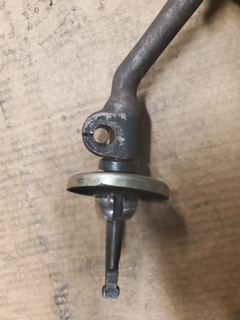
The next order of business is the installation of the shifter. On a separate excursion we managed to locate another Ford truck with a 5 spd manual transmission. At first, we grabbed just the shifter since that was what I needed for the FMT. Later we went back and retrieved the whole transmission and its associated hardware so we can have this golden unicorn on ice for a future build. As for the shifter, I still needed it for the FMT. I can source another shifter later for the other transmission when the time comes. There were a few issues though. One, the selector tongue is different on the FMT's transmission versus the tongue on the junkyard shifter. There's a flat spot on the tongue that allows for a retaining stud to be inserted all the way through to hold the shifter on the tongue. This flat spot was 90 degrees off from the flat spot on the other tongue. To solve this problem and be able to use the shifter on the FMT's transmission, I would have to put a new flat spot on the shank of the tongue to allow the placement of the shifter to line up properly. I used an angle grinder to make that new flat spot so I could put the shifter on the tongue and secure with the retaining stud.
Next I had to modify the transmission crossmember. The mount that we recovered from the junkyard transmission had studs that were spaced differently compared to the mount that was used on the FMT. Ironically, the crossmember had indentations that lined up with the studs on the junkyard mount. Most likely the factory stamped this crossmember with the option to cut slots for either type of mount. I ended up using a plasma cutter to cut out the extra slots then ground things down to be able to put the mount on the crossmember without risking cutting a hand on jagged edges.
Lastly is the oil pan. Since there is no provision for a dipstick, I chose to install a dipstick bung from a Powerstroke diesel engine. I filled the pan with 5 quarts of water then marked the line to know where the oil level will be when full then marked and cut a hole above this line using a hole saw. I installed the bung and oriented the dipstick hole to a forward angle so the dipstick can be at a position to make it easier to reach. I will most likely have to add something like a piece of hose with extra dipstick tube to allow for a dipstick to be positioned at the right spot for the tip to reach into the sump and register the proper level.
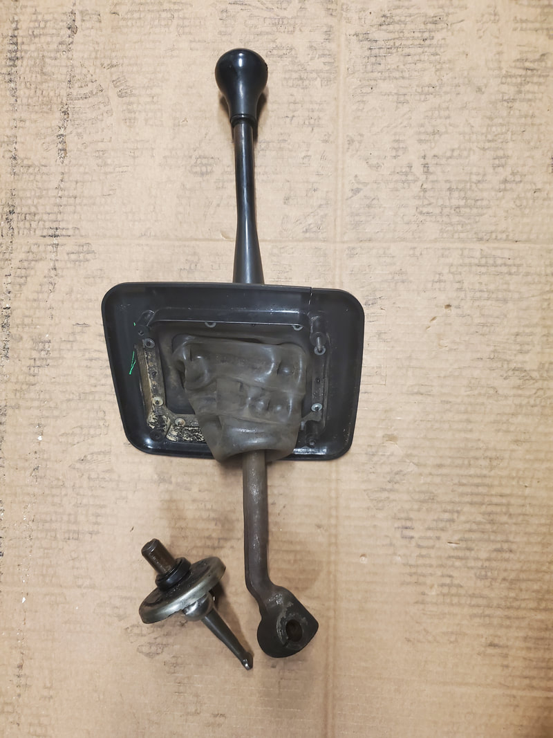
Our junkyard shifter with the selector tongue removed from the FMT's transmission.
With the shifter in the right position for the transmission, the selector tongue has its flat spot 90 degrees off from the stud opening in the shifter. The pic shows the stud hole and how the metal from the selector tongue is in the way and needs to be ground out.
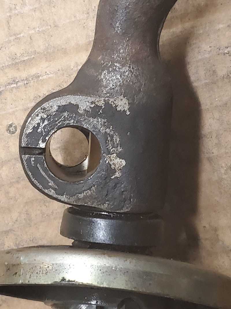
A closeup of this issue shows how the excess metal is in the way of the shifter's retaining bolt.
Extra flat spot ground onto shank of selector tongue. Note how new flat spot is 90 degrees off from old flat spot.
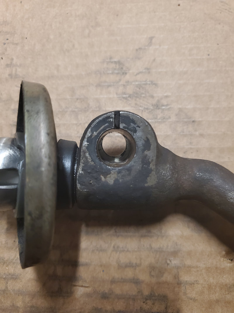
With tongue in the shifter handle, flat spot now shows in the stud hole after orienting the shifter in the way it needs to be.
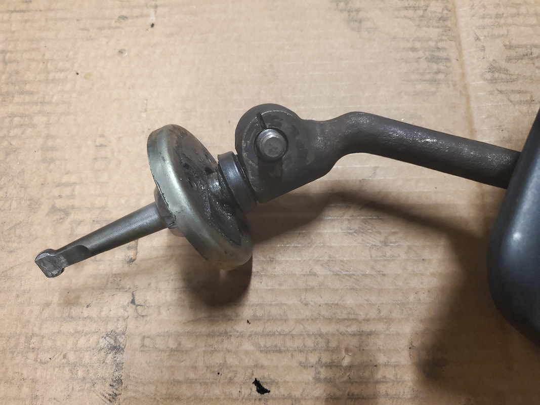
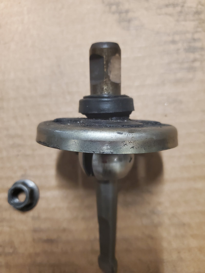
Retaining stud in shifter handle, locking in the shifter from moving around unnecessarily.
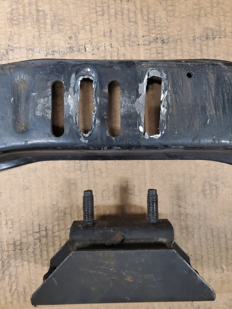
Transmission crossmember after cutting out extra holes with plasma cutter. Note how mount studs line up with these new holes.
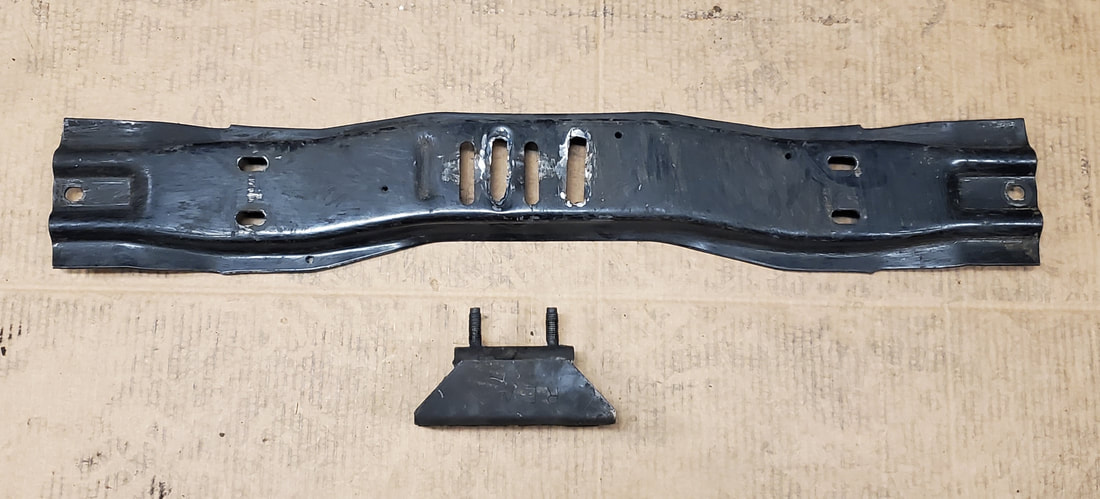
Shot of whole crossmember with mount.
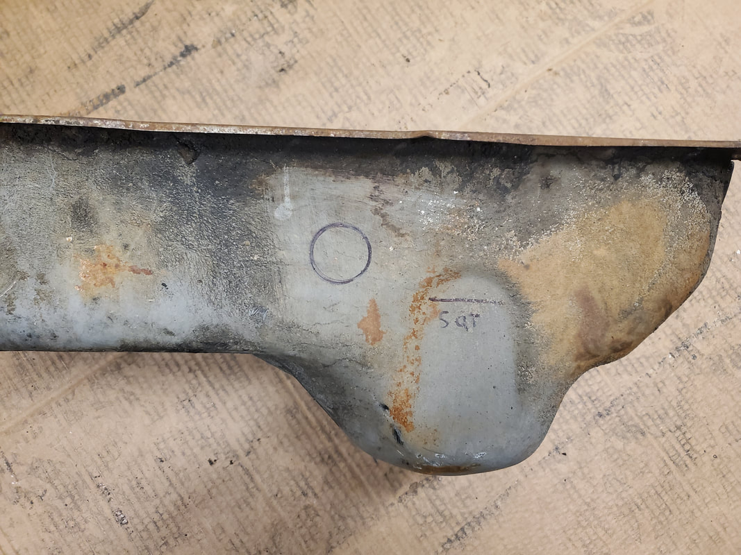
Markings on oil pan showing where oil level is at and where the dipstick bung will go.
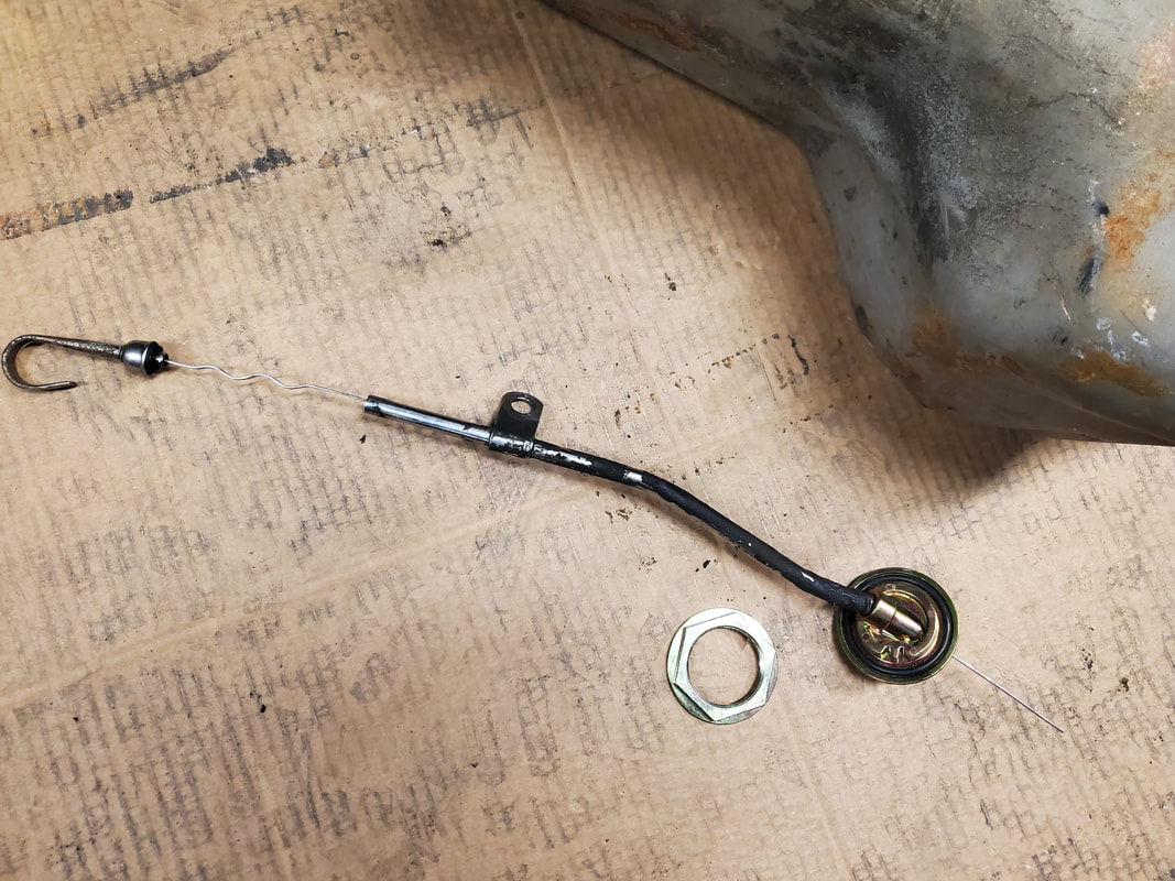
Oil dipstick with bung for oil pan.
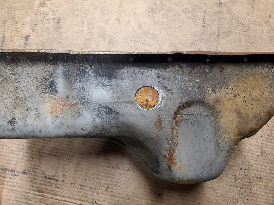
Hole cut in side of oil pan using hole saw. I had to use grinding wheels in a die grinder to widen the hole just a little before the threaded portion of the bung would fit in the hole.
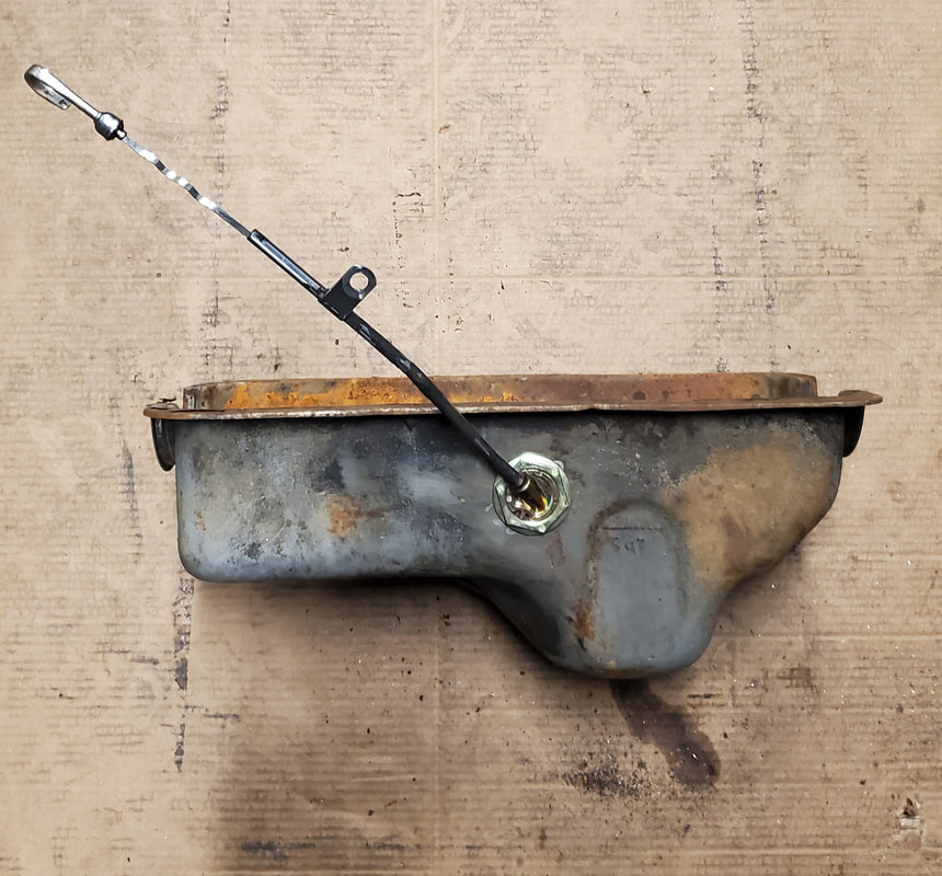
Oil dipstick bung mounted on oil pan with dipstick inserted inside. Note the angle of the dipstick, showing how marked end of dipstick would go into the sump and into the oil to indicate the level.
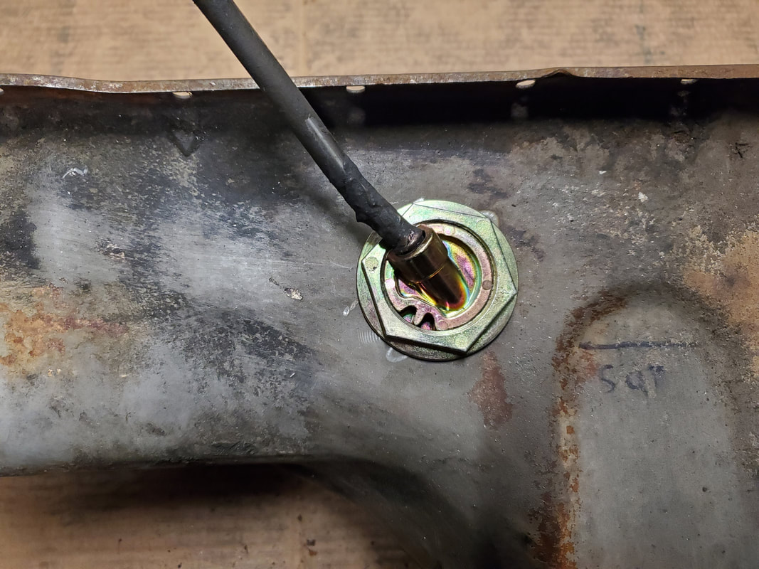
Closeup of bung with dipstick inserted.
Shifter mounted on transmission with base mounted on floor with drywall screws.
Left side of shifter base after mounting, note how there's a gap on the floor where I cut too much out of the floor before I installed everything. This hole will have to be filled in using a piece of sheet metal and some round head self-tapping screws, all mounted under the carpet to keep things low profile.
Transmission crossmember after installing on frame. Mount had to be secured with one bolt to allow the piece to be swung at an angle to mount the crossmember in place using nuts and washers. I was then able to swing the crossmember onto frame lips. Because of the fact this transmission doesn't really fit, I can get the crossmember to swing at an angle enough to reach one of the mounting holes. I'll have to drill another hole in the opposite side frame to secure with a second bolt. Of course, I installed the 2nd mount bolt once everything was in.
Closeup of mount studs with washers and nuts in place. Note angle of crossmember relative to the studs.
While under the truck I took the time to install the fuel pump. The pump is a generic electric pump that comes in a kit with a bracket to hold the unit anywhere there's a hole present to accommodate a bolt. It also comes with an inline fuel filter and two hose barbs to go on either side of the pump/filter assembly. Lastly it has two short pieces of hose and hose clamps to secure the whole works to the ends of a fuel line where one would install the pump. I planned on installing the pump along the frame rail just in front of the fuel tank, putting the pump as close as possible to the fuel tank to lessen the strain the pump will go through in drawing fuel from the tank. The fuel line as well as the wire harness that was feeding the fuel tanks also runs inside this frame rail. I was able to tap into the wire harness to get the power wire and ground needed for the pump, while cutting out a section of the fuel line to install the pump assembly. The bracket was secured to a spot on the frame rail where there was a hole drilled from the factory. Other than the carburetor, the fuel system is done.
The other thing taken care of while under the truck was getting the transmission crossmember secured. I ended up taking the one bolt loose that was holding the crossmember and drilling two new holes after positioning the unit in a spot that suited me. After securing the crossmember I was able to tighten the mount nuts, finishing the crossmember/mount setup.
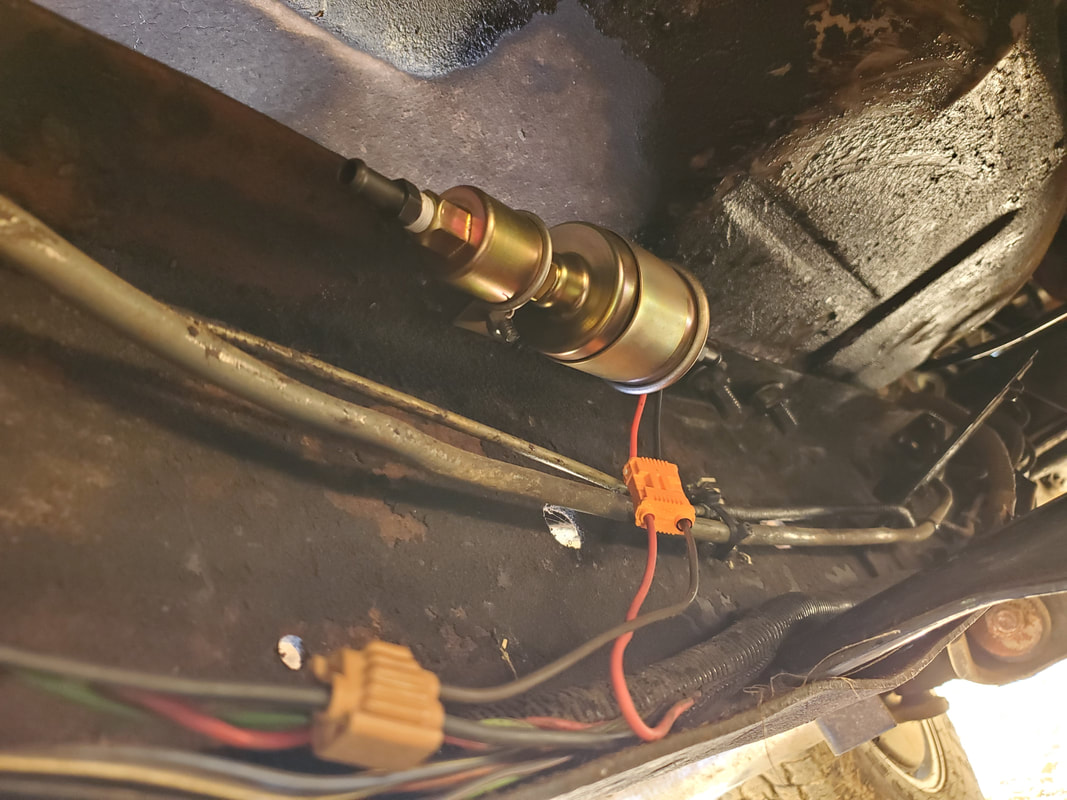
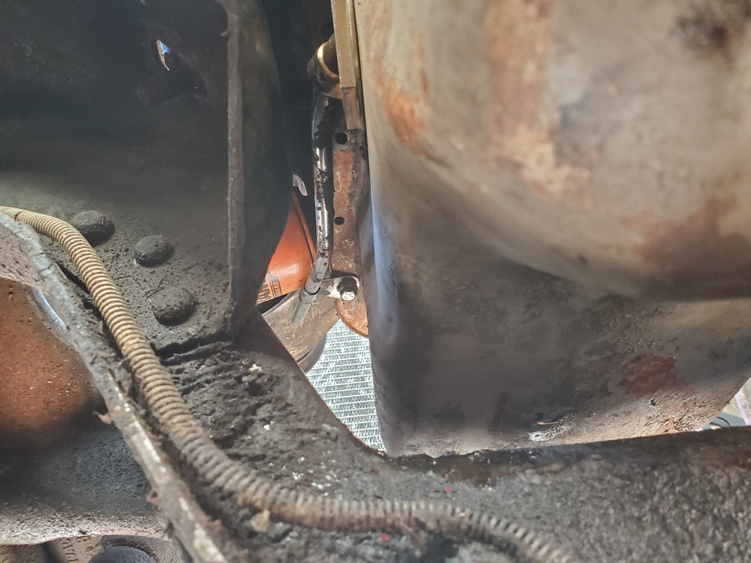
Fuel pump assembly installed with bracket to frame rail. Note the two conductor male/female plug set used to connect the fuel pump wires to the wires going into the wire harness. The power wire was cut from the wire harness to be ed into the plug for the fuel pump while a short piece of wire was added and spliced into the ground wire with a 3-way connector, noted at the bottom of the pic.
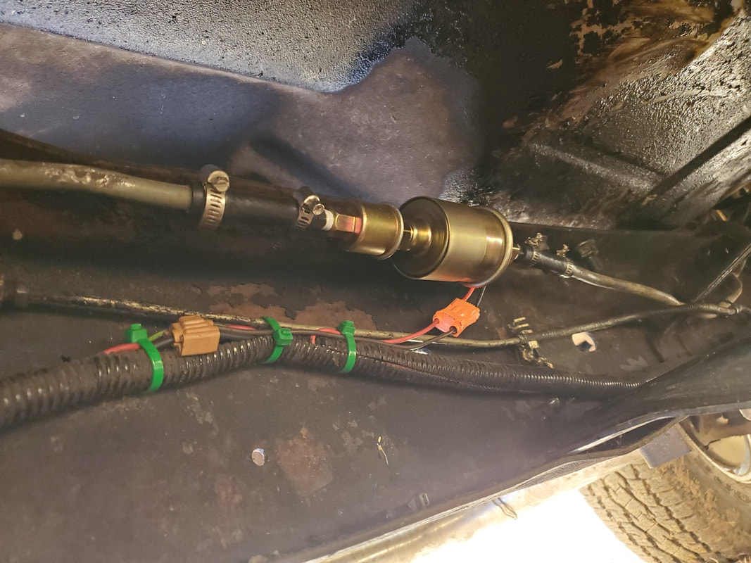
Fuel pump fully installed with wires zip tied in place and hoses/clamps in place connecting the pump to the ends of the fuel line after cutting out the section to accommodate the pump.
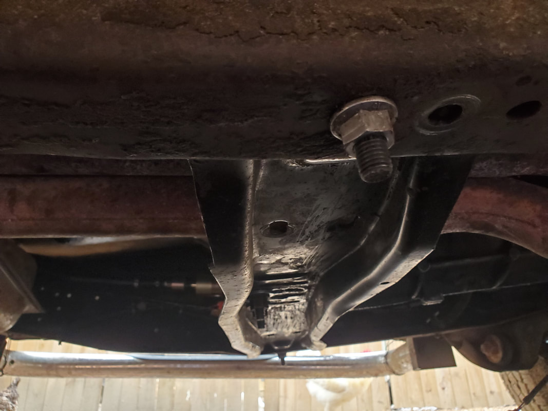
Transmission crossmember installed with a single bolt on either side holding the unit in place. Passenger side bolt is in the upper foreground and the mount nuts are in place.
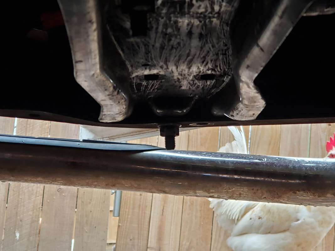
Left/driver's side bolt and nut holding crossmember in place on frame rail.
The next order of business is dropping the oil pan. Since the pan's sump section is sitting on the top of the K-member I would have to lift the engine up with the crane to even be able to drop the pan down from the block. I started off by removing the bolts, then positioning the crane and hooking up the chains which I left hooked to the engine due to needing to lift it again for the oil pan job. After lifting the engine up, the rear of the oil pan dropped down, dumping most of the oil out. I couldn't drain the oil due to the drain plug sitting on the top to the K-member. Also because of the front sump, I wasn't able to drop the pan down at the front where I could slide it out from behind the K-member. Luckily, I was able to slide the pan out from the front of the K-member and out, especially since there was no fan or fan shroud in the way. Pulling the pan the rest of the way caused the rear to dip down more, dumping the remainder of the oil on the ground. With the pan out I was able to drop the engine all the way on the mounts. I would've had to do this anyway to get the crane out of the way and be able to slide underneath the truck to scrape the old gasket off the block in preparation to install the new pan and gasket.
Another thing that I also managed to take care of was sourcing another slip yoke for the transmission. After another foray to the junkyard, I was able to find a yoke that fit the tranny as well as the driveshaft, so all is perfect due to the savings of $400 that I would've had to pay for a new shaft. I put everything back together with the driveshaft so with that done, there's not much left to buy or install before this truck will be ready to crank over.
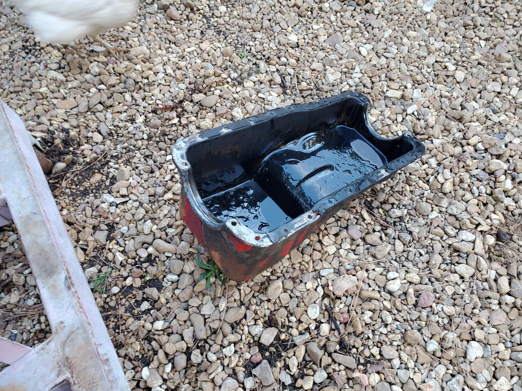
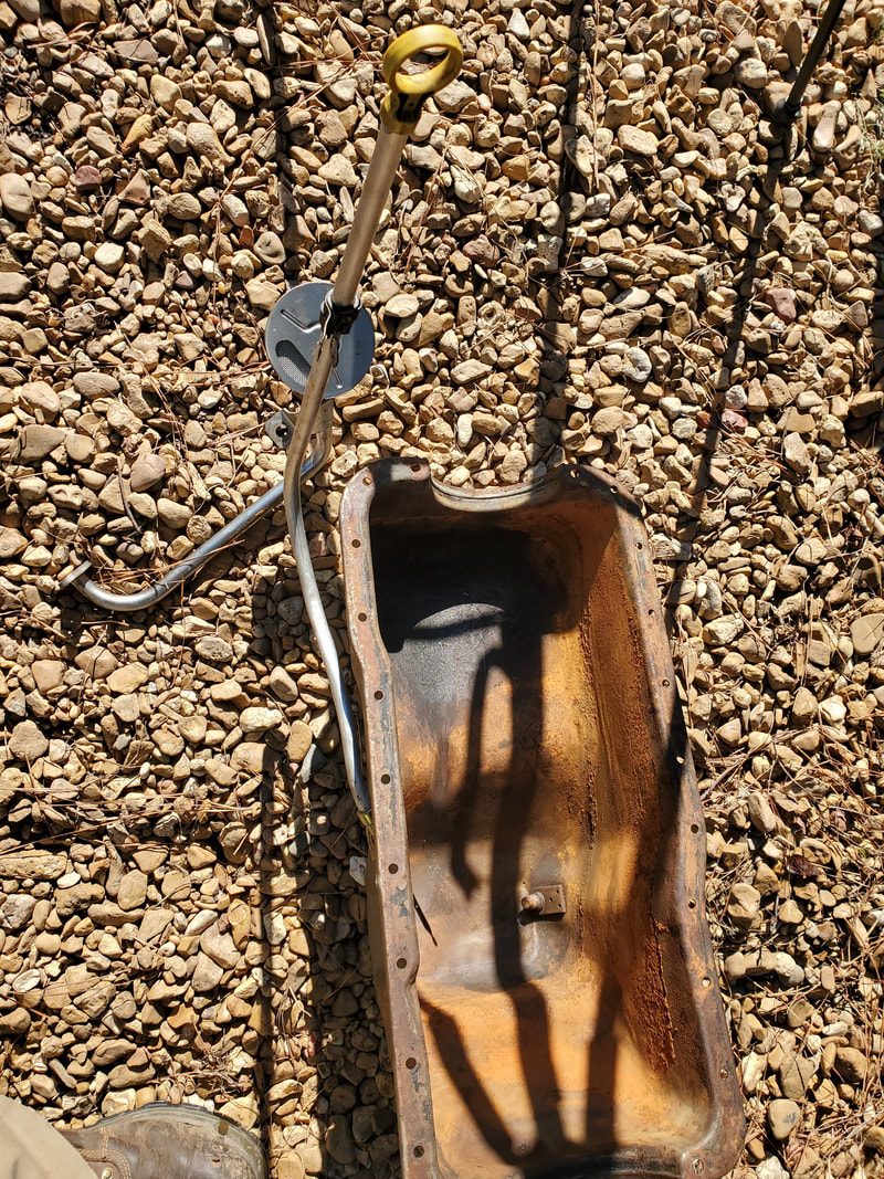
Front sump oil pan removed from engine.
Engine after lowering onto mounts, note the extra room around the engine now that it sits lower.
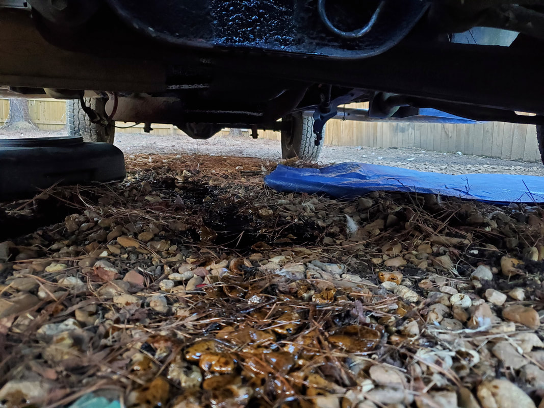
The environmental disaster after removing the oil pan. Oil everywhere.
A shot at the inside of the engine after removing the oil pan, barely visible in the waning light, even with flash....
New used slip yoke installed on FMT's driveshaft. After getting the measurements required, I was able to use a digital caliper to measure the yokes we found at the junkyard to get the proper sized unit. We managed to find one that matched in every way (shaft size, # of teeth, spacing for U-joint) where I was able to install it immediately with no extra work.
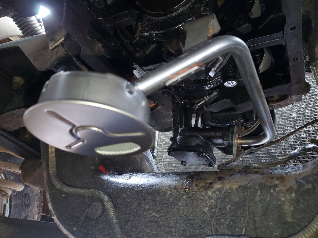
One thing I wanted to do before I proceed any further was test fit the rear sump oil pan with the side mounted oil dipstick bung to check for any interference issues between the bung and other objects like the motor mount or oil filter. Because of the shape of the oil pan, I was unable to insert the pan under the engine from the rear even after hoisting it up with the engine crane. I ended up having to insert it from the front, the same way I removed the old oil pan. Only problem is because of the shape, again, it ended up interfering with the crank pulley. I ended up having to remove said pulley to give me the clearance to allow me to insert the oil pan from the front of the engine. Once under the engine I immediately noticed the upward angle of the bung would have the dipstick going up into the motor mount. Because of this I ended up orienting the port on the bung to about a 10 degree angle up from horizontal. This would have our current dipstick going forward to just under the power steering pump. If I stick with our current dipstick, I would have to check the oil by reaching under the power steering pump to grab the dipstick. Now this wouldn't be that big a deal, especially since the angle of the dipstick actually has the tip hitting just below the 5qt level as marked on the oil pan. Also, a retaining loop on the dipstick is present, which I utilized by twisting it to the right angle to allow me to secure it to the oil pan via one of the mounting holes. I used a couple bolts to hold the pan up to make things easier for me to fit and adjust things already. I used a nut as a spacer and a longer 7/16" bolt, going through the loop and into the bolt hole for the oil pan, holding the dipstick stationary. Only other thing I'd have to do is use some epoxy to seal the tube in the bung hole. Another option is to source some fuel line or brake line that is the same diameter as the bung hole, then bend the tube to route the dipstick up behind the power steering pump so it can be accessible in a normal spot versus under a component. I'd have to source a longer dipstick but would cut the amount of tube I'm using based on how long the dipstick is. Either way we can make it work since our dipstick does actually work for us.
Inserting the rear sump oil pan from the front of the engine, note the missing crank pulley.
The orientation of the port on the dipstick bung has it going up into the motor mount that'll be right above it when the engine is seated on the K-member.
Oil dipstick in place in the bung after orienting the port to 10 degrees above horizontal. Note the retention loop that is held in place with a spacer nut and longer bolt in a bolt hole on the oil pan. Also note its position relative to the power steering pump.
The next action to be done was replacing the rear seal on the transmission, as well as replacing the driveshaft. After picking up a replacement seal, I fabricated a tool using a couple PVC fittings in order to tap the seal in. Once the seal was back in, I was able to slide the driveshaft slip yoke in. From there I seated the rear of the shaft on the rear and put the bolts in, getting the driveshaft done once and for all. From there I moved on to the oil pickup, another part we picked up along with the rear seal. I bolted up the pickup to the engine then turned my attention to the oil pan and my new dipstick tube idea.
I picked up a piece of aluminum tubing to use for a dipstick since it was almost the exact diameter of the hole on the dipstick bung on the oil pan. I had to drill real out the hole on the bung in order to be able to insert the tube enough to be able to keep it seated in the thing. I had to install the oil pan in order for me to make the bends I need to ensure proper fitting of the homemade dipstick tube. Funny thing is that I had to remove the oil pickup to get the oil pan back up, but then reinstall the pickup from inside the pan while the pan was down enough to be able to maneuver between it and the bottom end of the engine. I used a propane torch to heat the tube to make the bends and after multiple times sliding under the truck to determine how much to bend the tubing, I finally got the dipstick tube bent the way I wanted. The tube would come out from the bung then bend up just behind the power steering pump. I removed the oil pan one last time to do a final fitting of everything which included the dipstick. I ended up having to borrow the Elco's dipstick as it was long enough to fit in the tube. In order to get the tip of the dipstick to reach where the full level would be, I had to trim about six inches of the top of the tube off. Once that part was done, I was able to install everything.
We picked up a one-piece oil pan gasket which is a way easier install than the old school four-piece set. After reinstalling the oil pickup, I seated the gasket and got the pan up and fully secured. With the pan up I took the dipstick and smeared gasket maker on the end of the dipstick tube, then inserted the tube in the bung. To help keep the tube stationary, I added a bracket/brace near the top of the tube that would allow the dipstick tube to be secured to the engine via an exhaust manifold bolt. Once that part was done, I also added another bracket/brace near the bottom of the dipstick tube and secured it to a bolt point on the lip of the oil pan, using a washer for a spacer and a long bolt to reach through and into the block to seat the brace. With that the dipstick tube was fully secured.
With the oil pan and dipstick in place I put the starter in and wired up the main battery cable and starter solenoid cables, zip tyin everything together to keep things nice and neat. From there I reinstalled the flange assembly of exhaust pipe that I cut off to open things up underneath. Using a couple of couplings and the welder, I was able to weld the pieces together, slide the pipe assembly onto the greater exhaust and tack weld the other end of the couplings to help ensure things will stay together. I bolted up the flanges to the exhaust manifolds, concluding that part of the project.
I installed the new radiator hoses next, taking time to ensure the top hose will sit high enough to keep the cooling fan from hitting it. After bolting on the fan clutch, I then dug out one of my many 4bbl Edelbrocks and an air cleaner stud so I can focus on getting that part installed on the engine. Once that's done there isn't much else to do on the truck before I can attempt to start it up.
Transmission rear seal and PVC pipe fitting tool put together to install the seal by tapping the tool while its against the lip of the seal, evenly pushing the seal into the transmission tailshaft.
Slip yoke and driveshaft installed in tailshaft of transmission.
Rear plate on driveshaft bolted to rear end.
Oil pickup bolted up to oil pump.
Aluminum tube to be used for dipstick with tip ground down a little bit to help it fit in the dipstick bung.
Tube stuck inside bung hole for fitting purposes.
Oil pan in place with oil pickup mounted from between the pan and the engine.
Dipstick tube test fitted after bending to have it come up just behind the power steering pump.
Dipstick tube after heating with torch to make bending easier. I bent the tube around an old fire extinguisher to be able to make the bends without kinking the tube.
Bracket/brace installed on tube to secure to exhaust manifold bolt.
Tube test fitted in bung one more time before prepping for final install.
Oil pan removed again with pickup while dipstick tube is test fitted with dipstick from Elco.
Tip of dipstick pointing downward past where oil level would be at when full.
Installing the one-piece oil pan gasket.
Gasket maker smeared on tip of tube prior to insertion into dipstick tube bung.
Dipstick tube pressed into bung with gasket maker smeared around bung hole to help seal things up even more.
Brace secured to exhaust manifold with bolt to hold tube stationary.
Second brace secured to oil pan lip using washer as a spacer with a longer bolt to hold it in the block.
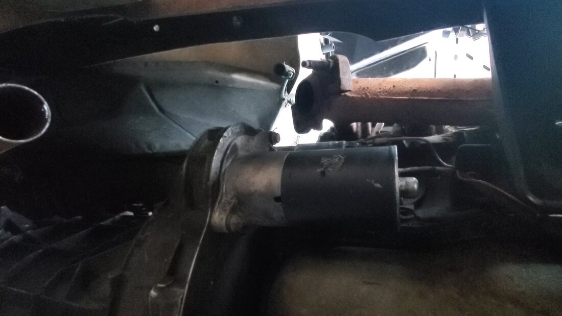
Starter installed on bellhousing and completely wired up.
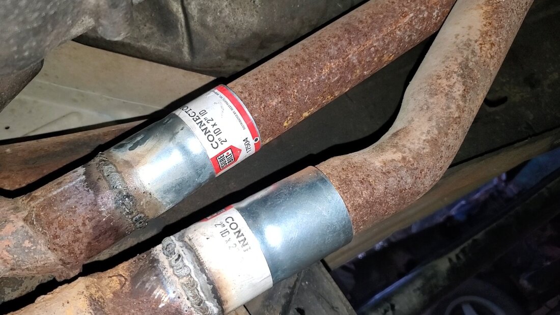
Pipe couplings welded to flange pipe and then pressed onto greater exhaust system.
r end of couplings tack welded, poorly, onto greater exhaust pipe. U-bolts will most likely be used to further secure the other end of the couplings so nothing will be likely to come loose.
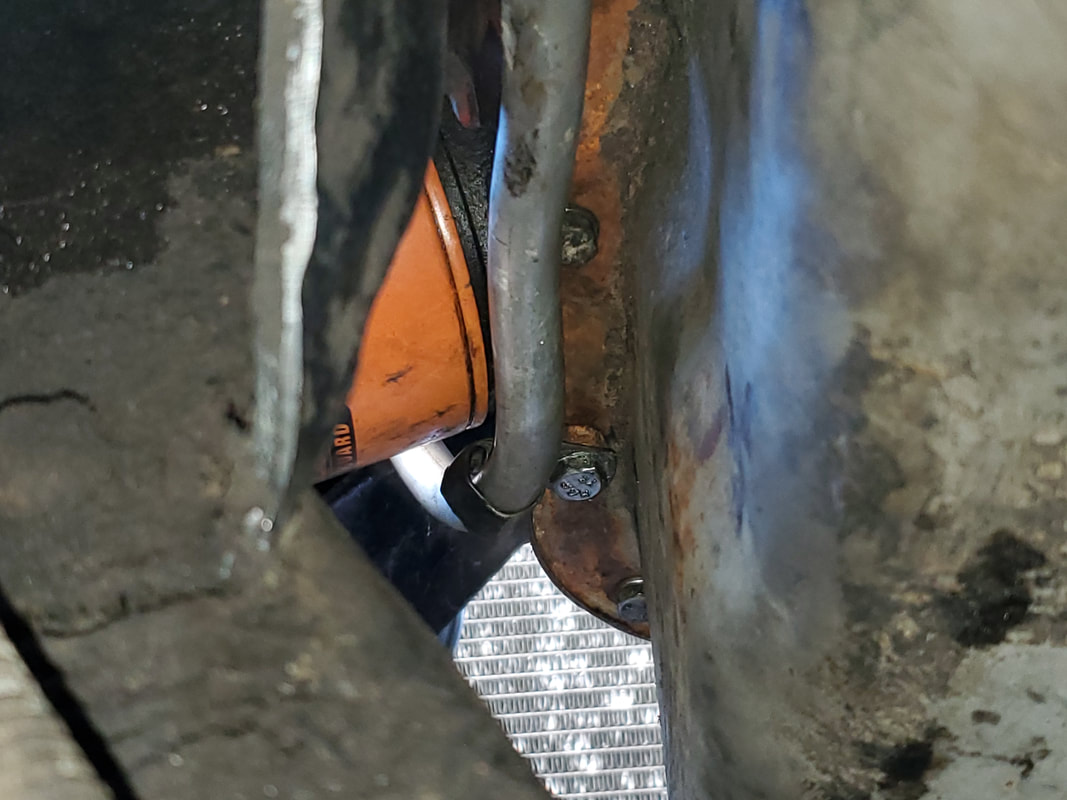
Flange pipe attached to exhaust manifolds and hanging like its supposed to under the truck.
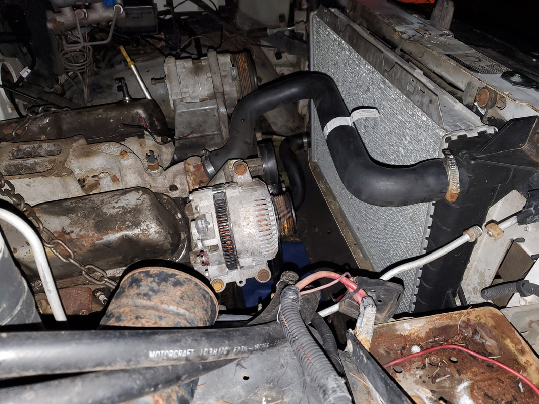
Radiator hoses attached to engine and radiator.
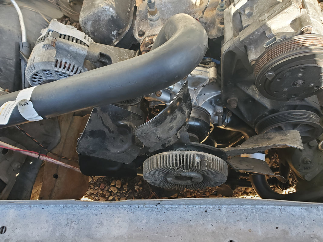
Cooling fan attached to water pump.

Edelbrock 4bbl carb, gasket and air cleaner stud staged on top of engine for future installation.
In order to bolt the carburetor down, I had to take a set of bolts that were a little longer than I needed and trim them down to allow for the gripping of enough thread in the intake, even with the gasket in place. Once the carb was secured, I had to address the fuel line. Since there was a female compression socket in the carb, I decided to use a male compression fitting with some 3/8" metal tubing. Digging some from the scrap pile I bent a fuel line that would route to the front of the carb down to the left behind the AC compressor and power steering pump and downward towards the end of the main fuel line on the left frame rail. I would've installed a plastic fuel filter at this junction, but it would've put the filter over the exhaust manifold, not a good idea. I just coupled the ends of the metal lines with a short length of rubber fuel hose, which is more heat tolerant than the plastic fuel filter. After making the section of fuel line and securing it to the carb and the main fuel line, I turned my attention to the throttle cable.
To address this situation, I had to replace the throttle cable. The stock cable was way too long since the trucks EFI throttle body was placed where it required an extra-long cable. Luckily, I had a shorter cable that I salvaged from either the 73 Mustang or the Toyota truck, both of which were turned into chicken coops. I removed the old throttle cable and enlarged the hole in the firewall for the new cable. I then took a conduit bracket and modified it to secure the base of the cable. I ground the center of the bracket to be a U shape to slip it over the base of the cable. I bent the bracket to where the bolt holes lined up with the bolt holes in the firewall. I was able to attach the bracket and get the new throttle cable secured. Next, I took an angle brace and drilled a hole close to the bend in the brace. I trimmed the excess metal after the hole, making the brace look like an upper-case L. I then secured the brace to a stud bolt on the intake, just behind the carburetor on the left. Securing with a nut, I was able to then attach the throttle cable end to the brace with a nut and bolt. The cable end portion has an anchor base that consists of a single bolt point. Lastly, I removed the snap clip from the end of the cable since the carburetor lever didn't have the ball tip required for the cable to snap onto. I attached a nut and bolt to the carb lever then attached the end of the throttle cable to the threaded end of the bolt with another nut and washer to secure the whole assembly. A spring attached to the bottom of the carb lever and the bottom bolt hole on the angle brace on the intake finished things up.
The last thing I did was add another fuel filter on the fuel circuit right after the fuel pump. Since I didn't put a filter on the line on top of the engine, adding one right after the pump would be the smartest choice. To do this I just detached the fuel tube from the output side of the pump and pushed the whole section of fuel line forward a few inches, taking into account that I would have to bend the end to allow the rubber hose to remain straight between the main fuel tube and the last section going up to the carburetor. I added the fuel filter and a short piece of hose to the output of the pump and secured the fuel line with extra zip ties to keep the metal tube from moving excessively. With that the fuel circuit is complete, now for some more electrical crap.
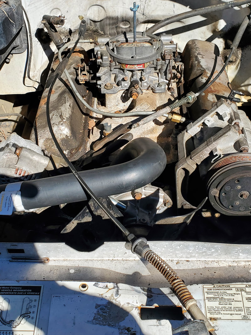
Carburetor bolted to intake and both throttle cables are present, with shorter one in place for installation.
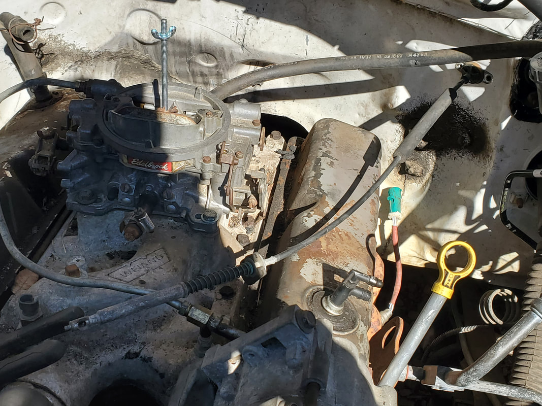
New shorter throttle cable in place with base plugged into firewall via enlarged hole.
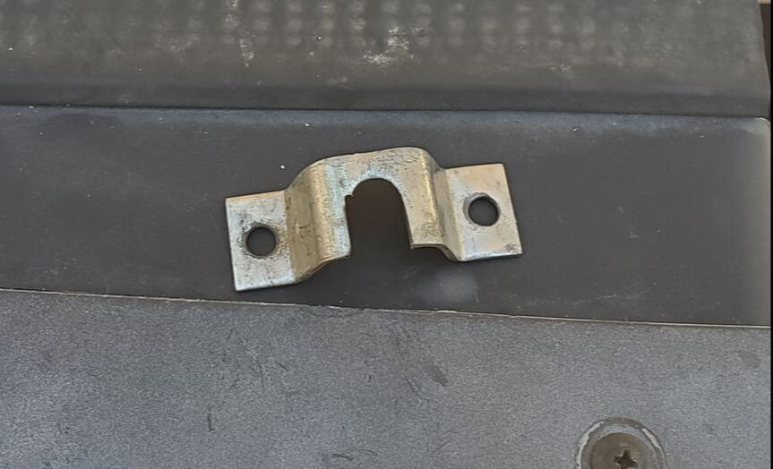
Conduit strap modified to secure base of throttle cable to firewall.
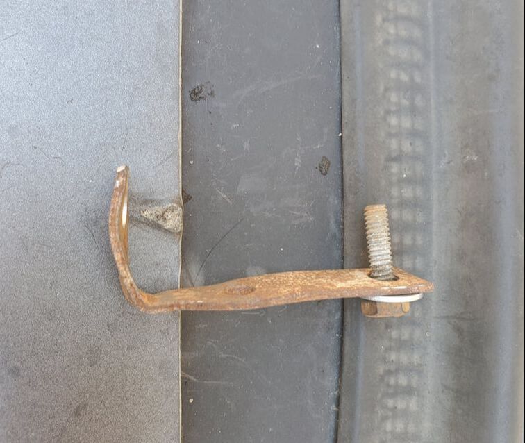
Angle brace prepped to hold throttle cable above intake, in line with carburetor throttle lever.
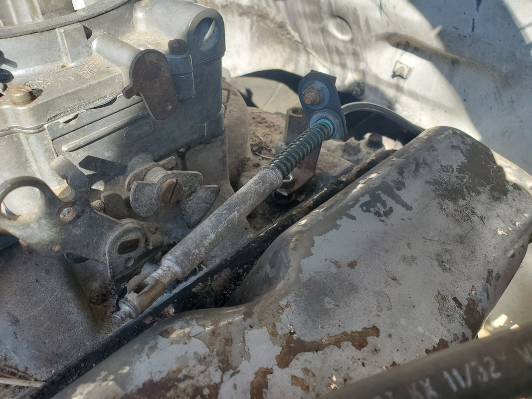
Angle brace in place on intake and throttle cable bolted to brace.
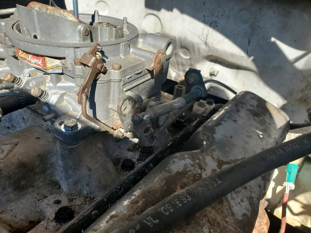
Throttle cable secured to carburetor and angle brace. Note return spring in place as well.
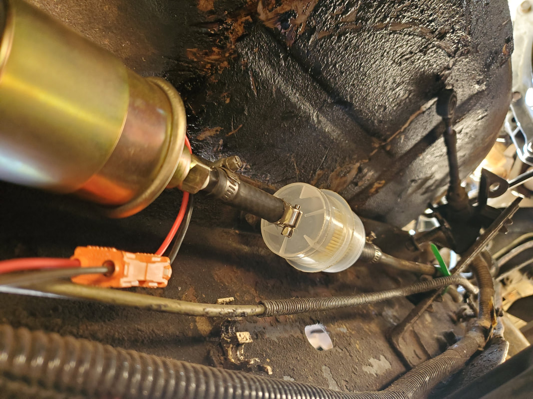
Fuel filter installed after fuel pump in the fuel line circuit. Note green zip tie to right holding metal tube in place.
After getting the extra fuel filter installed, I turned my attention to the plug for the fuel selector switch. I pulled the dash/gauge panel free to expose the inner area in order to get to the wires better. After identifying the line feeding power to the fuel pump, I made a jumper and tried to see if the pump would come on. Meanwhile, the beepers in the dash were making all kinds of chirps and chimes when the key was turned on. I kind of figured the ECU was doing some cray stuff due to the fact that nothing from the old EFI system remains. At the same time, I thought about the idea that there's still the fuel gauge that has to be taken into account. Now I could've added a second jumper for the fuel gauge but then I figured, I might as well just put the selector switch back in. Besides, even a dead switch looks better than a giant hole in the dash. For shits and giggles I installed another jumper from a dead circuit that was still hot, one feeding the computer-controlled transmission that no longer exists in this truck. After confirming that the pump was fine, I put the selector switch back in. First of all the crazy chimes stopped. Second, I realized something else. The ECU still had some control over even the fuel system. When I turned the key on, the fuel pump came on for a couple seconds then turned off. I realized that the ECU was cycling the pump on the same way it does with the high-pressure pump in the EFI system. The ECU turns the pump on to prime the system then shuts off. During startup it will cycle the pump on again to keep the pressure in the system until startup then hold the pump on after the engine is running. Because of this, I had to leave the extra jumper that would allow power to continue to feed the fuel pump when the key is on. I installed the dash panel with the selector switch, satisfied with the current arrangement. I will have to put the power wire onto the side going to the pump and add a diode to block back feed through the selector switch, in order to make a crude security switch that would disable the fuel pump by merely switching to the rear tank. The engine will crank but never start. It would be one of a few security measures but a simple one, nonetheless.
The next area that needed addressing is the starting circuit. A couple times I tried to crank the starter to no avail. After troubleshooting and finding no power getting to the solenoid, I traced the wire back to the ignition switch then ohmed out the wire at different points until I found an issue right at the plug in the firewall. After reseating the plug, I still kept getting a reading of 550 ohms, telling me that there is some kind of high resistance in this area. Contrary to what I wanted to do, I ended up running a bypass wire from the ignition switch through the firewall over to a point on the wire after the engine bay fuse box. I bypassed the fuse box as I had some weird issues at this spot too. Rather than dig into this point and risk compromising another circuit I just bypassed all of it and ran right to a point on the wire after the fuse box, cutting out everything between those points. After doing that, the starting circuit worked as intended, firing off the solenoid.
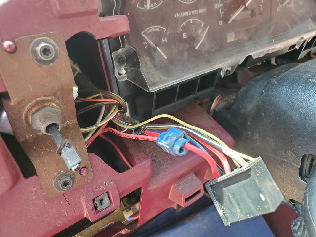
Selector switch plug with splice for jumper going to fuse box in order to allow the fuel pump to cycle on when the key is on.
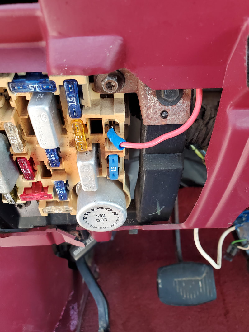
Jumper wire plugged up to fuse terminal that was feeding the transmission. Fuse was pulled and jumper plugged to 12v side of the fuse.
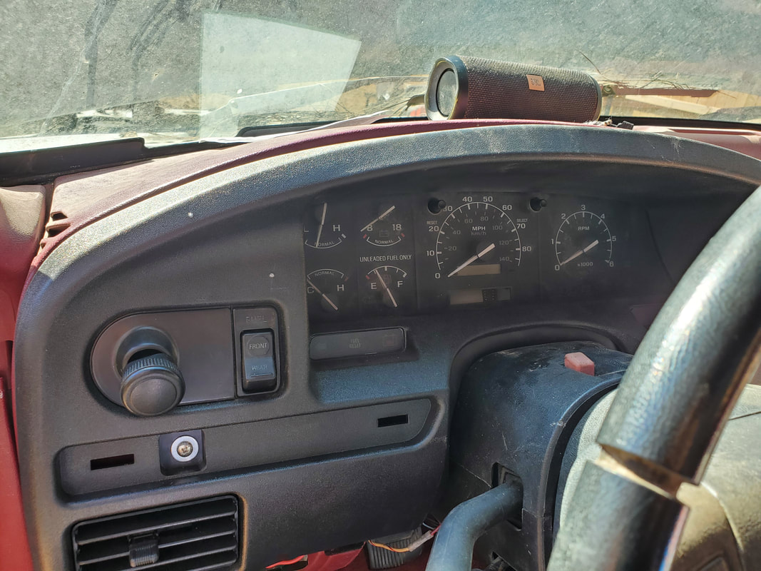
Gauge panel reinstalled with selector switch installed. Looks a lot better than a big hole.
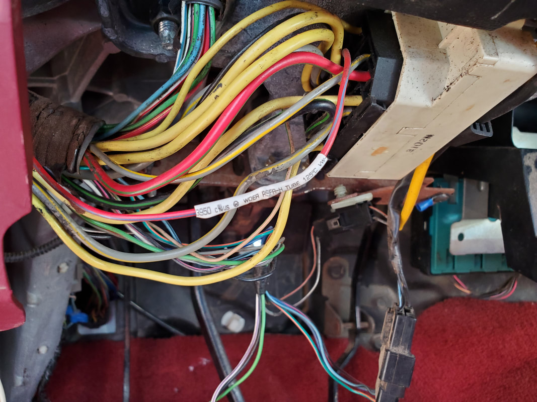
Splice at ignition switch where bypass wire goes into firewall. White heat shrink tubing indicates the splice.
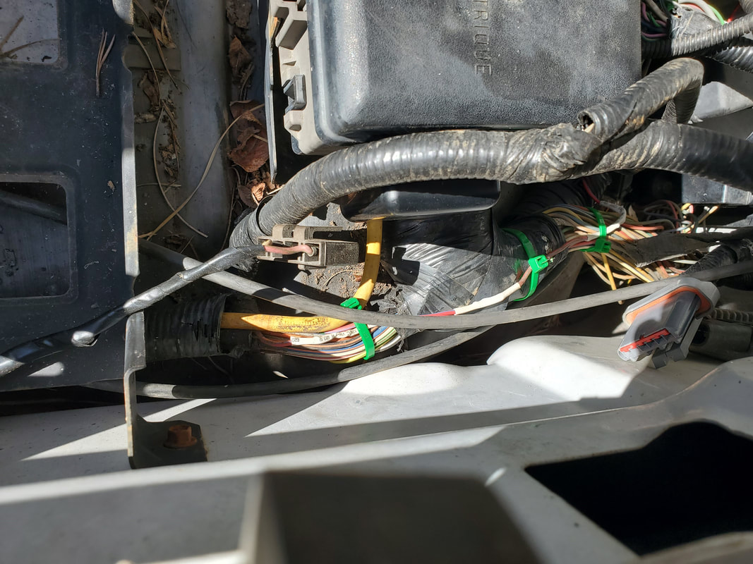
Closeup of the splices where the bypass wire has been hooked up. The white heat shrink tubing shows where the splices are.
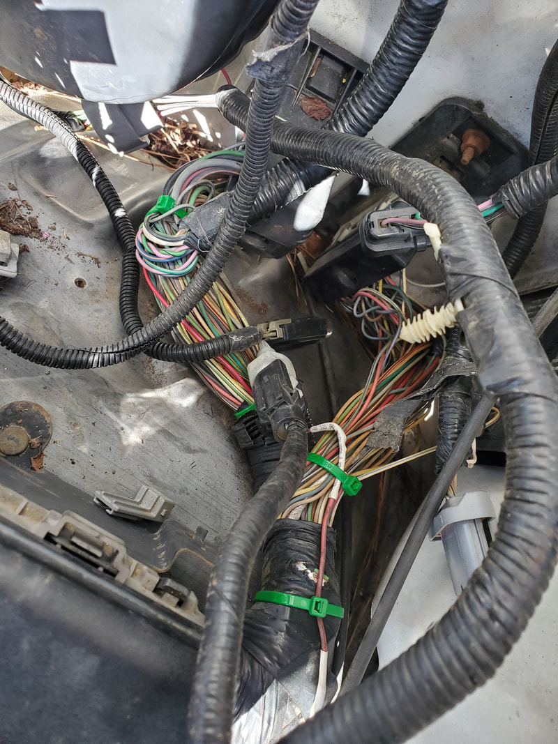
The path of the bypass wire, following the wire bundle to the firewall before going through a small hole in the firewall to the ignition switch. The green zip ties indicate where the wire has been secured.
We now get into the final stage of getting the truck ready for the first startup. First thing is the installation of a replacement smog pump. Instead of trying to get a shorter belt and hope that it stays on the pulley network, I just decided to grab a junkyard smog pump to use until I can grab a smog pump delete pulley or fabricate one that would allow me to use the stock belt. After grabbing a decent pump and installing it, I turned my attention to the heater hoses. I had to take a bent section of metal tubing and cut a short piece of hose to connect that tubing to one of the ports on the water pump. The metal tube routes up and around the accessory bracket, putting the port up at a spot where the rest of the heater hose can be hooked up to go to the heater core. As for the other hose, I had to remove it and install a slightly longer hose and connect it to a port on the rear of the intake. I also had to install a 90-degree short hose between the port on the thermostat housing and the water pump. With that, the cooling system was complete. I also added the hose from the brake booster to the back of the carburetor. I used some heavy-duty zip ties to hold the metal tubing to the accessory bracket to keep the hose from getting dangerously close to the serpentine belt that runs right by the hose.
The next thing to be done was the installation of the HEI distributor. With this hybrid distributor, installation isn't as straightforward as it would be with a Duraspark or a points distributor for a SBF engine. Because of the large size of the base of the distributor compared to the size of the valley where the unit rests. In the case of our setup with the aftermarket intake, the base of the distributor hits the intake runner. Luckily the base has an indentation that allows the unit to rest at home, as long as the unit is oriented a certain way to allow the indentation to sit around the intake runner. Another thing I had to address was the grinding down of a spot where a plug goes. This surface just needed a fraction of an inch removed from the edge to allow the edge of the distributor to go down just a little more. Once the dizzy was at home with the orientation putting the vacuum diaphragm on the right side, I was able to lock things down and get the wires on. I had to remove the right valve cover in order to watch the rocker arms as I rotated the engine in order to get the #1 cylinder at TDC (top dead center). Once at TDC, I was able to select which terminal on the distributor cap would be #1. I installed all the wires on their respective plugs, but because of this being an already made wire set, most of the wires were longer than necessary. This is fine as its better to have the wires too long than too short. Worst case I'll trim the wires down later and install new ends so I can make the wires to fit. I can then use those wires as a reference to make new wires from raw stock afterward.
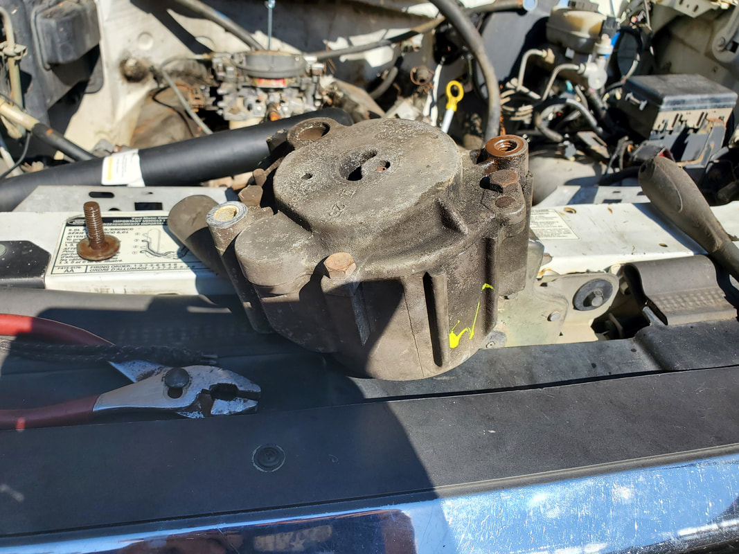
The junkyard smog pump, awaiting installation. Pulley had to be removed in order to remove the pulley from the donor truck as well as reinstall.
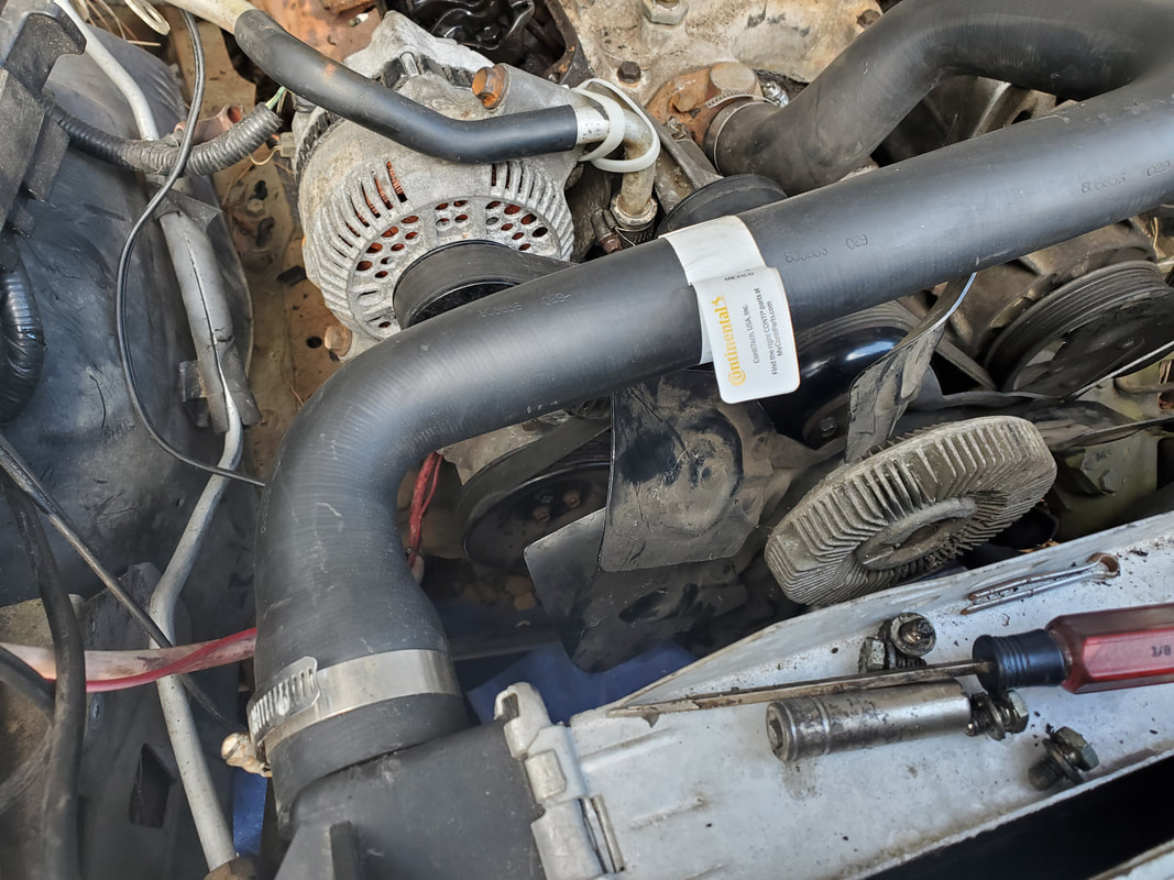
Smog pump tucked away under alternator with serpentine belt installed. Also note the zip ties holding the metal tube for the heater hose.
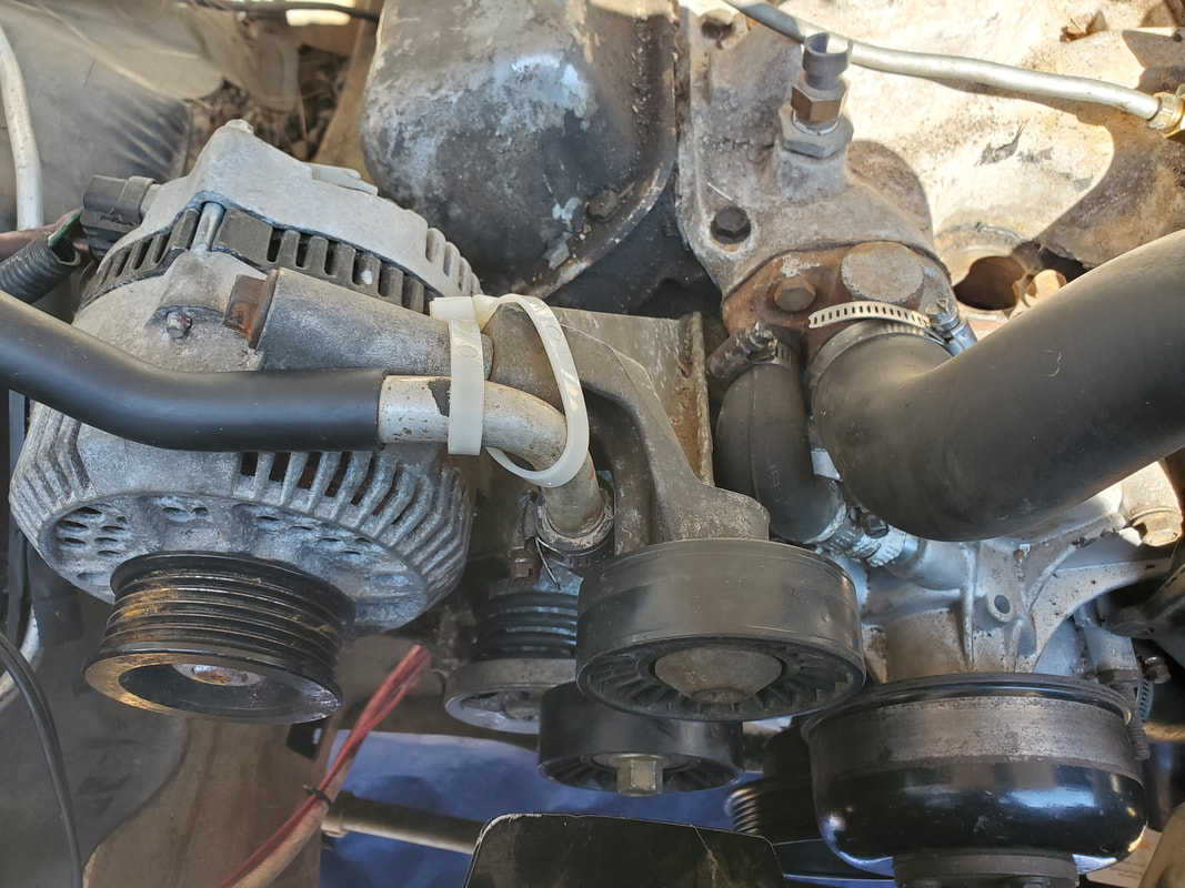
Heavy duty zip ties holding metal tube for heater hose against the accessory bracket to keep the hose and tube out of the path of the serpentine belt.
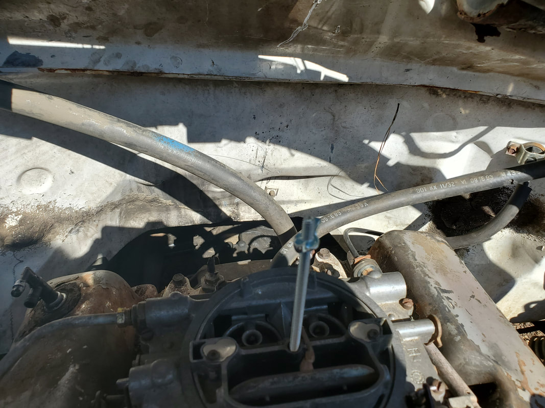
Heater hoe hooked up to coolant port on rear of intake. Also note the air hose from the right, hooked up to the rear of carburetor, going to the brake booster.
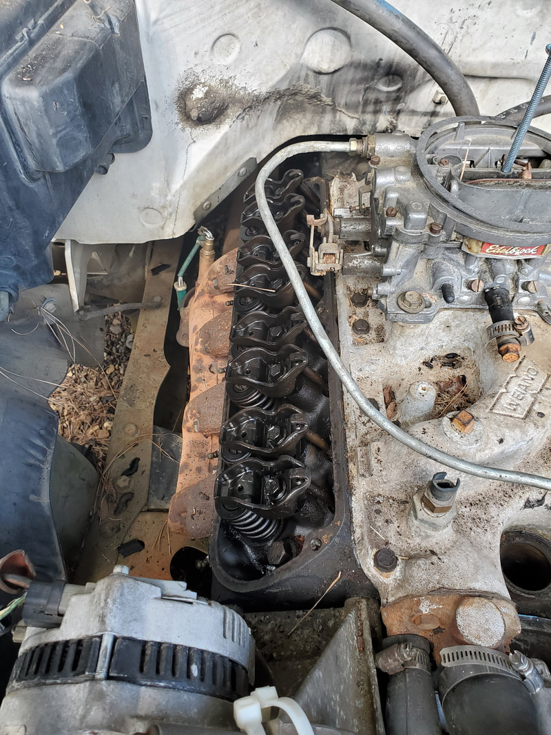
Right valve cover removed in order to watch rocker arms' movement to get TDC on #1 cylinder.
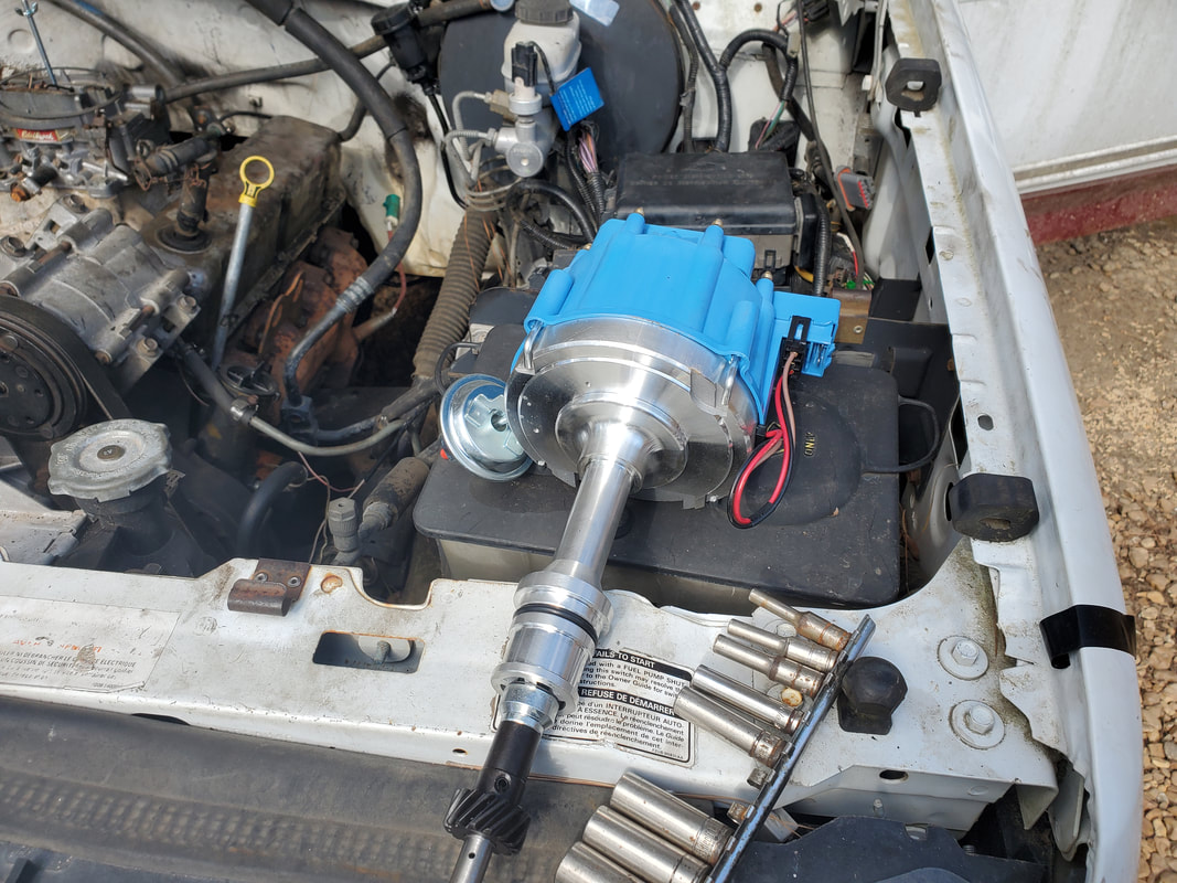
Hybrid GM HEI/SBF distributor ready to be installed in engine.
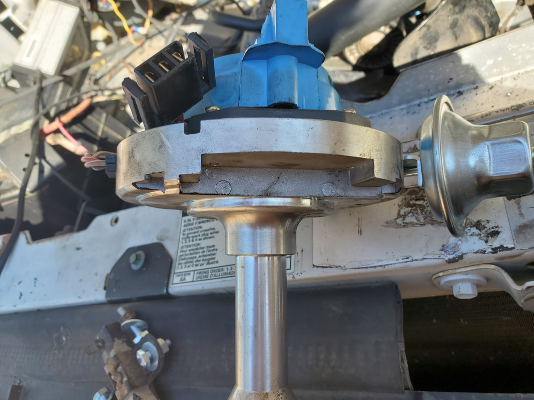
Indentation on distributor's base that allows the unit to be able to clear the intake runner and go down more on its base.
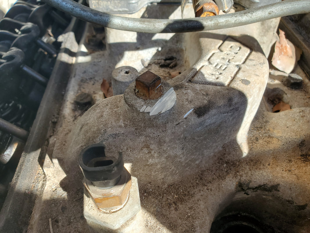
Port on intake runner that had to be ground down to give the little bit of extra clearance for the distributor body to be able to go down a little more.
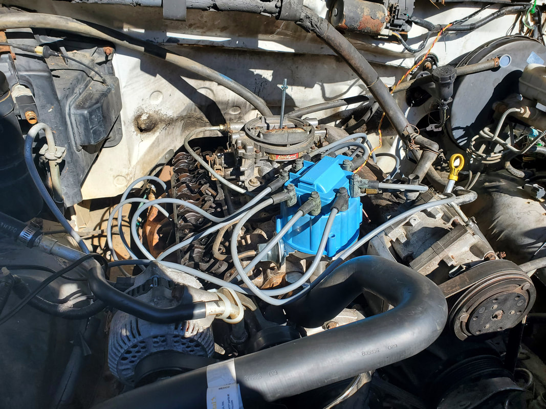
HEI distributor in place with wires installed. Note the excess length of the wires.
With the time finally having arrived to try and start the truck for the first time, what do I discover? The starter was shot. Yep, the starter we picked up from the junkyard when we got the other 5spd tranny was no good. Desperate, we got a new reman starter from Auto Zone and threw it in. At the same time, I had to replace the section of fuel line that went between the fuel pump and the last section of line before going into the carb. After getting the fuel pump to prime itself, I still got no fuel up at the carb. After separating the lines and trying to blow through the metal line on both ends, I found it was clogged. Replacing the fuel line did allow me to have the flared compression fittings on the end of the line where it connected to the last section that snaked around the top of the engine and over to the carb. The rubber hose that I had on the old metal line is no more, so the potential fire hazard is also no more. With those things addressed I went ahead and tried to start the truck.
When I finally did get the engine started, we had to play around with it to try and keep it running. I found that I had to hold the choke closed part way to even allow it to stay running, even at a high RPM idle of around 2k RPM. Also, the valve covers were leaking enough to warrant extra attention. I ended up taking the valve covers and cleaning them up and gluing the cork gaskets in place. I did take time to flatten out the indentations around the bolt holes before applying the gaskets so I can get a better seal. A thin layer of gasket maker on the outside of the gaskets helped further seal the valve covers on the heads.
The next thing was adding a choke cable. A universal choke kid had everything I needed to get the cable attached under the dash in the cab as well as attached in the right spot on the top of the intake behind the carb. Extra hardware held the cable in place and a fitting on the choke linkage on the carb held the wire core of the cable. With that I had a fully working manual choke. I took time to verify that there were no air ports on the intake or carb that I missed and went ahead and started the engine again. I was able to keep the thing running but when I tried to put it in gear to move it, the engine would buck and fart and sputter out at times. I tweaked the dizzy both ways with no real difference. I did do a double check on the clutch slave cylinder to verify there was no air in the lines and with that, was able to put the truck into gear, going forward in 1st and going in reverse. With that, I attempted a short test drive up and down the driveway.
When under load the engine bucked a lot and backfired a few times. i was able to get into 2nd before running out of driveway but was able to get up to the yard and park the truck in a new spot closer to the entrance to the yard. I do plan on checking the plugs to see if there's any excess carbon on them as well as double check the firing order of the plugs to make sure there isn't a couple of wires crossed. I also want to check the wire feeding the distributor from the ECU to determine if the voltage is too low due to outside regulation before going into the HEI system. I'll do this by installing a jumper straight from the battery to feed raw 12-13v power to the dizzy. If this doesn't take care of the problem, I'll try replacing the carb with one of the other spare units in stock. Even though these carbs are rebuilt, they aren't rebuilt where the bodies were able to be thoroughly cleaned to ensure air and fuel passages are free of contaminants that could adversely affect movement of air or fuel. This could be the problem with the odd running and the shitty smelling exhaust as well as backfiring. I won't know until I dig into these things deeper. The main thing is, we did get the truck running and did a short test drive. Worst case I will buy a new generic Edelbrock carb off Ebay for $300 to start fresh and if need be, install the old Duraspark ignition system in place of the HEI system in case that is proving to be a problem. There's definitely some more to do before we can advance to longer and more extreme road testing.
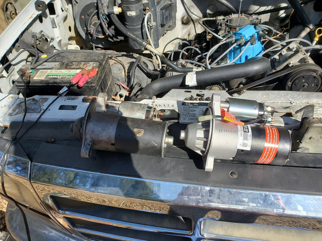
New starter with old starter. Despite their small size, these newer starters are pretty high torque compared to their older predecesors that are much larger.
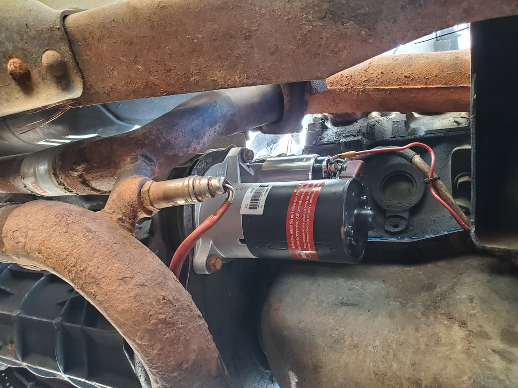
New starter installed in place, ready to perform work.
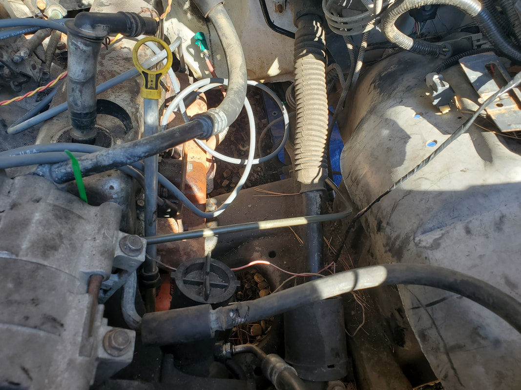
New fuel line, as indicated by the olive drab tube running from the frame over to the left behind the AC compressor.
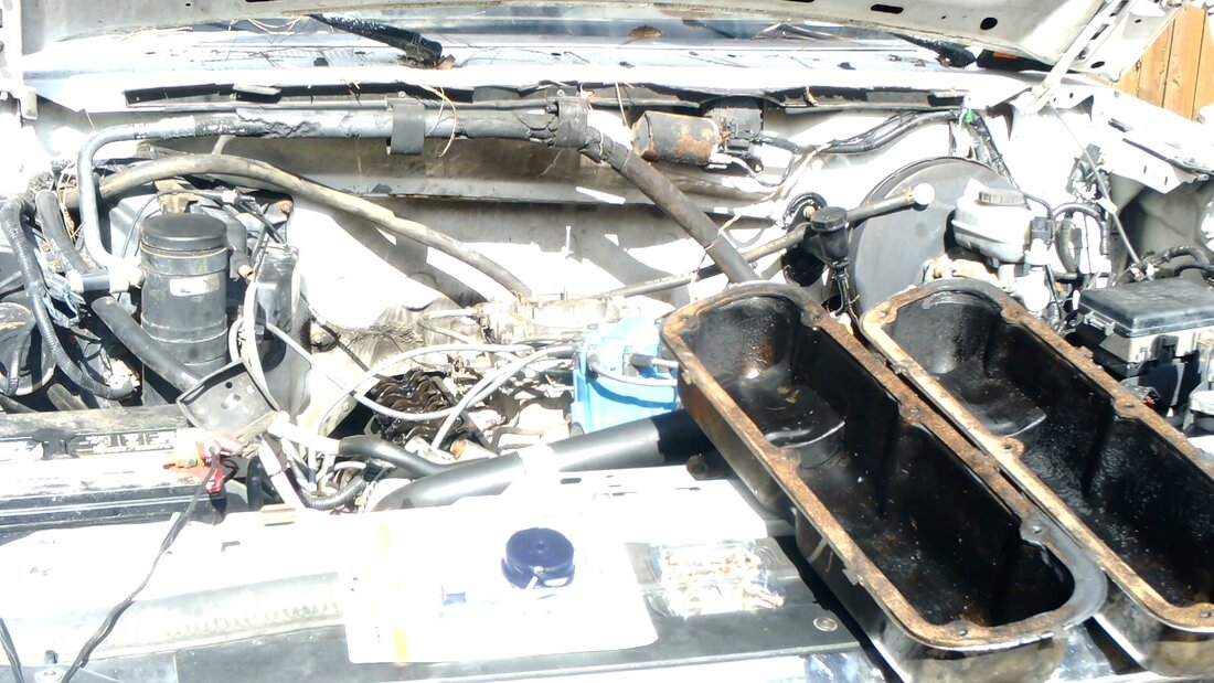
Valve covers with gaskets glued in place and ready to install. Note the choke cable kit to the left of the valve covers.
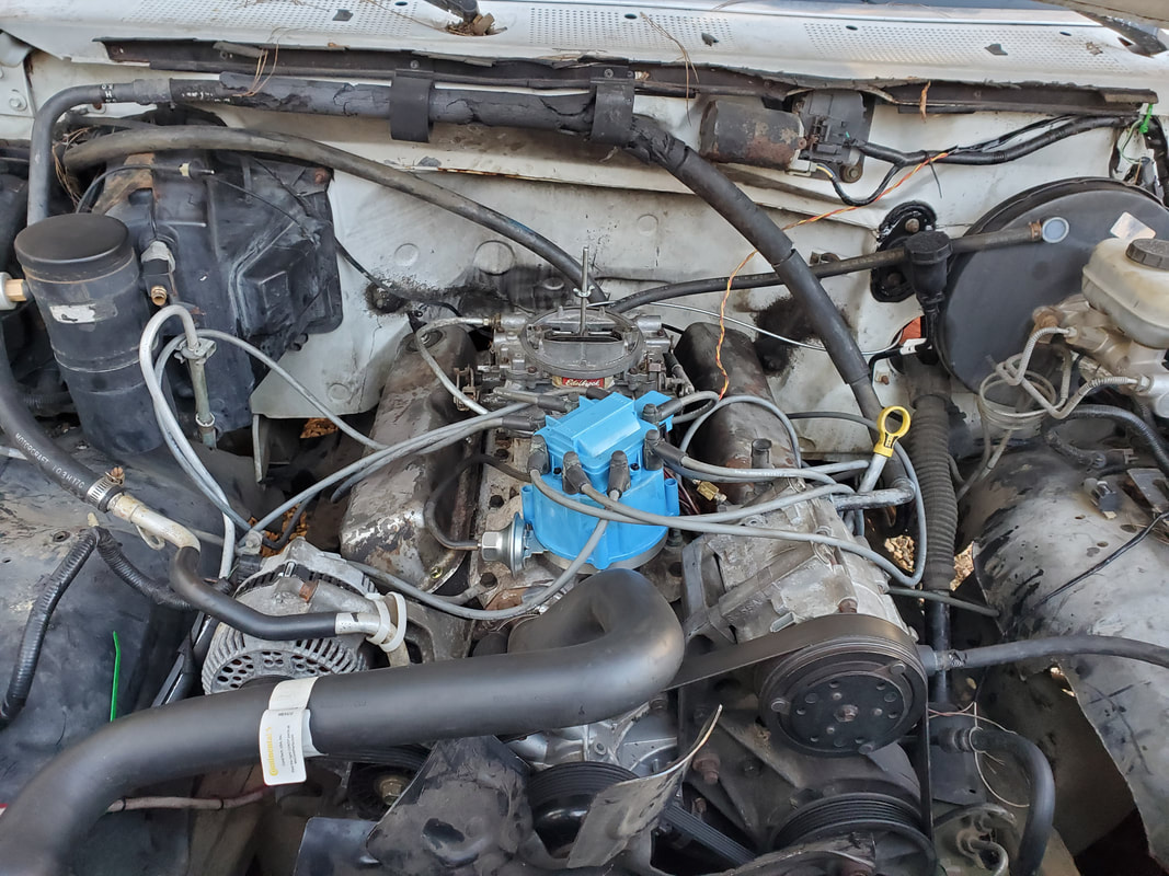
Valve covers installed back on engine with fresh flared head bolts and a thin layer of gasket maker on outside of gaskets to ensure a proper seal.
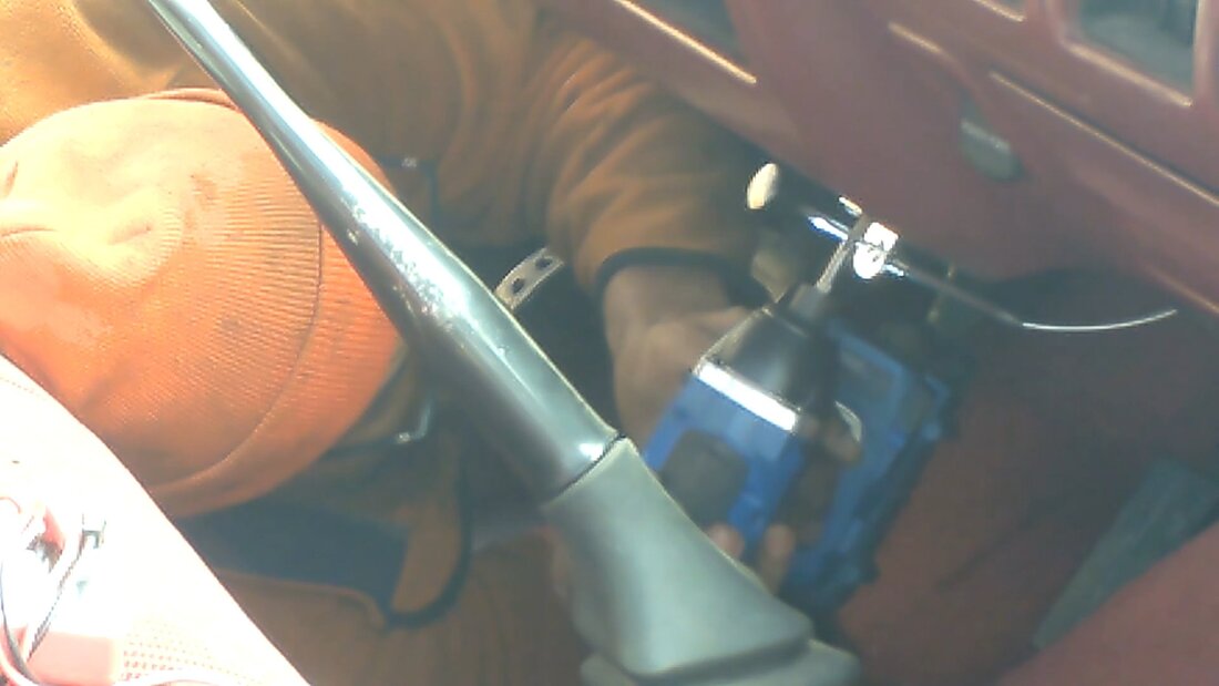
Installing choke cable knob end under dash with included bracket from kit.
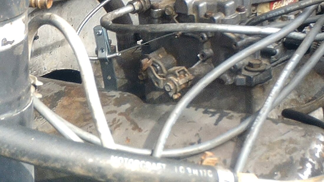
Bracket holding choke cable in place and choke linkage holding wire core of cable.

Testing out the FMT by going down the driveway.
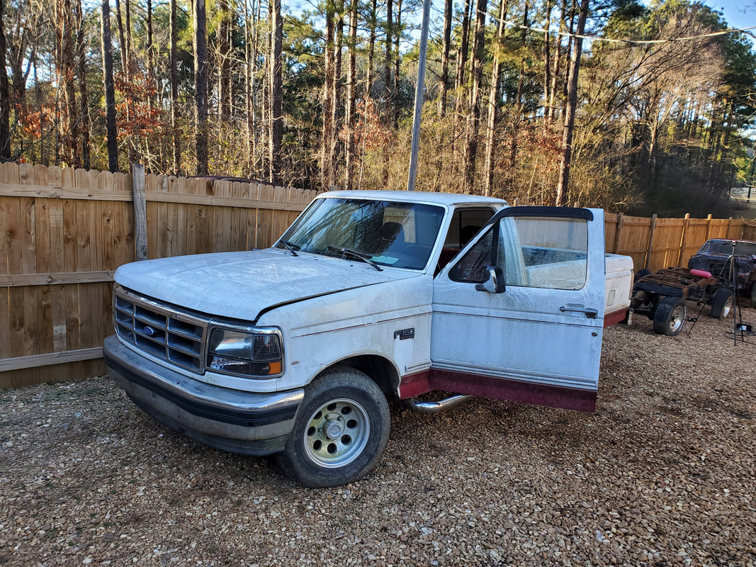
The FMT parked in a new spot to allow me to be able to work on the truck easier and be able to pull into the driveway for more testing.
Because of the issues that were observed with the engine my next move is stripping the top end of the engine so I can put my eyes on the valve train and all the associated components to see if there's any compromised parts. Of course this involves removing everything down to the short block. This includes the distributor, valve covers, intake, accessory brackets, exhaust manifolds, and the heads. At the same time the push rods will come out and when the intake is removed it will also allow me to pull the lifters out. As daunting a task as this may seem to some, the way I look at it, the sooner I jump in and get it done the sooner I can move on to the next phase of the project. Letting days pass without action is stupid since I could get a lot done in one week of just doing things versus one week of dwelling over why I don't want to do shit. Either way, with a couple hours time, I had the top end of the engine stripped off and was down to the short block. As I figured, the short block appeared fine, no scratches on the cylinder walls, pistons were straight and there were no carbon deposits that would be of any concern.
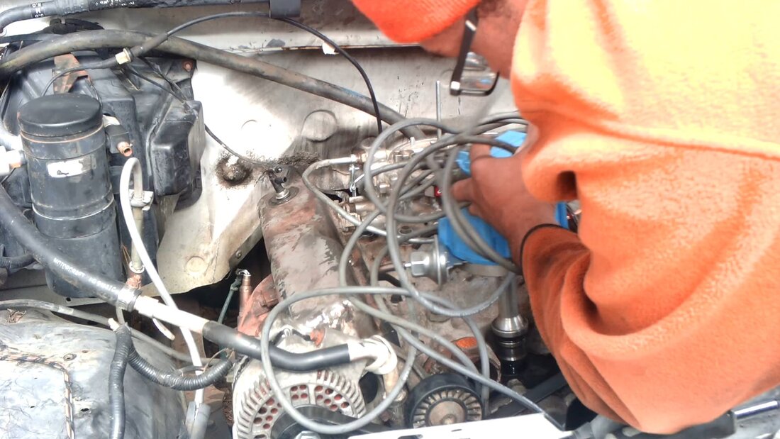
After draining the coolant and removing the top radiator hose, I pulled the distributor and its wires free to kickstart the stripping.
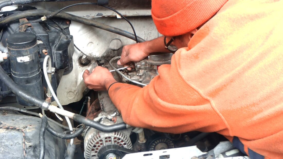
The next thing was the carburetor. After disconnecting the choke and throttle cables and vacuum hoses, four bolts are all that stood between me and removing this device.
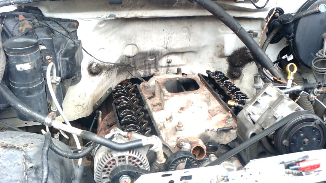
Once I pulled the valve covers off and seen there were no rocker arms that were off and the push rods were straight, I moved on to removing the intake bolts.
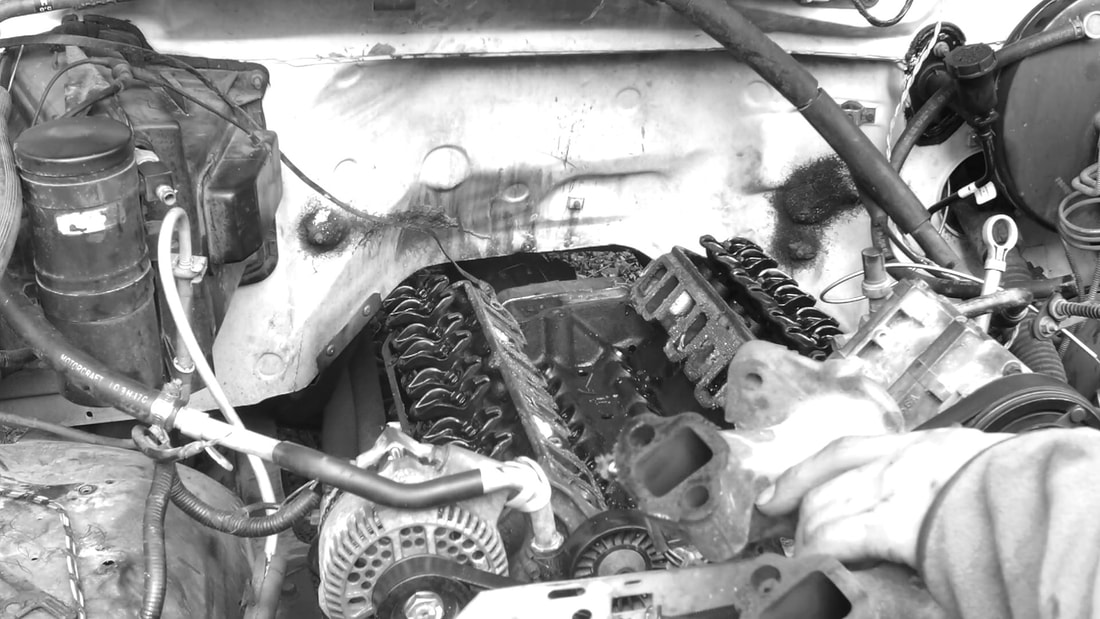
With the intake off, I moved on to the exhaust. Even after removing the bolts from the head, I still needed to separate the flange bolts in order to fully remove the exhaust manifolds.
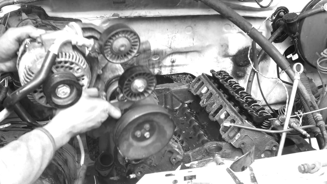
The next order of business was removing the accessory brackets since they're bolted to the heads.
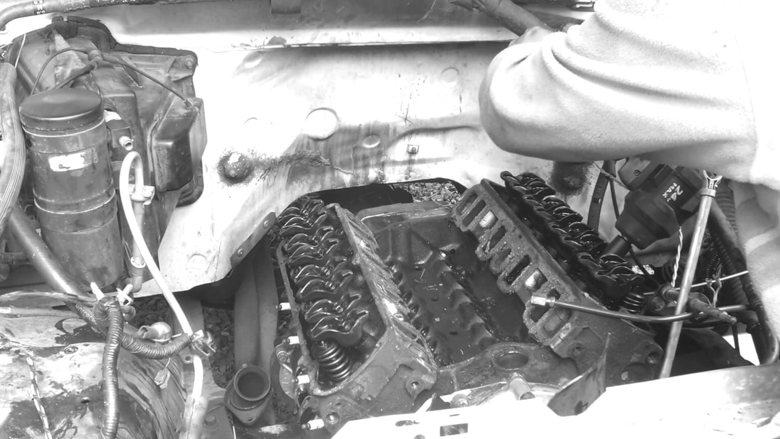
The impact wrench was only good for a few bolts as the tool was hitting on the other items in the engine bay. I had to use the breaker bar and ratchet to get most of the bolts off.
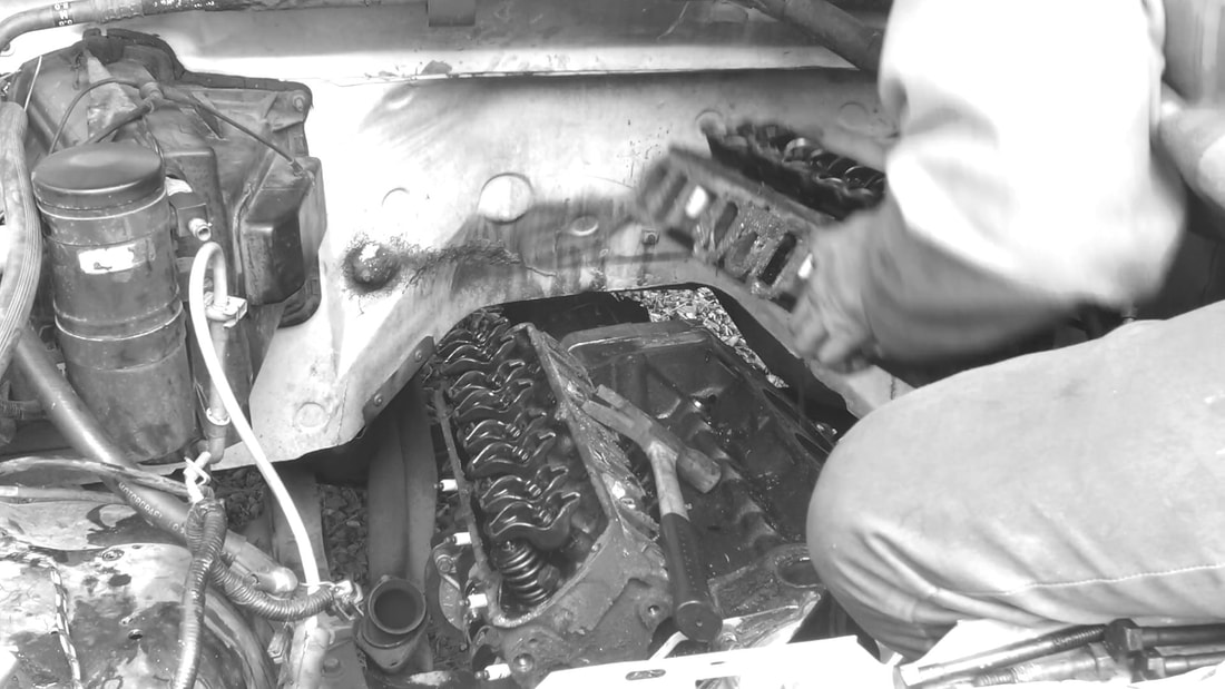
Removing the left cylinder head. It appears these bolts had loc-tite on them due to the coating of stuff on the threads of most of the bolts.
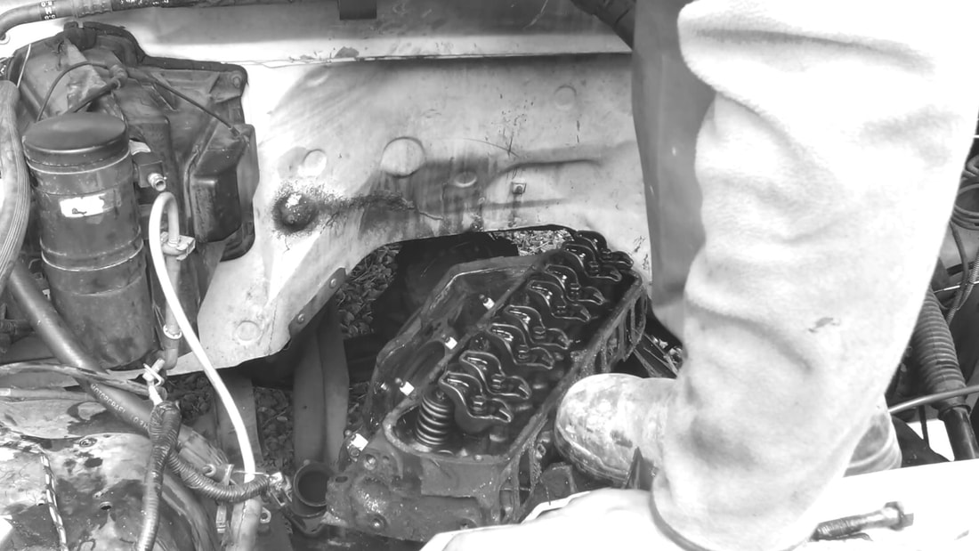
Removing the right cylinder head. There was also particulate matter on the bolts from the cooling system, meaning I will have to run this engine and flush the cooling system in the future to purge it of this trash that is floating through the water jackets.
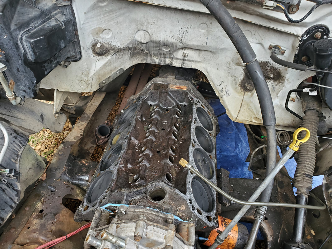
The short block after pulling the heads free. The cylinder walls are clean and the pistons are intact. The lifters have been removed as well. I took time to clean the top of the block off in preparation to put the new head gaskets on later on.
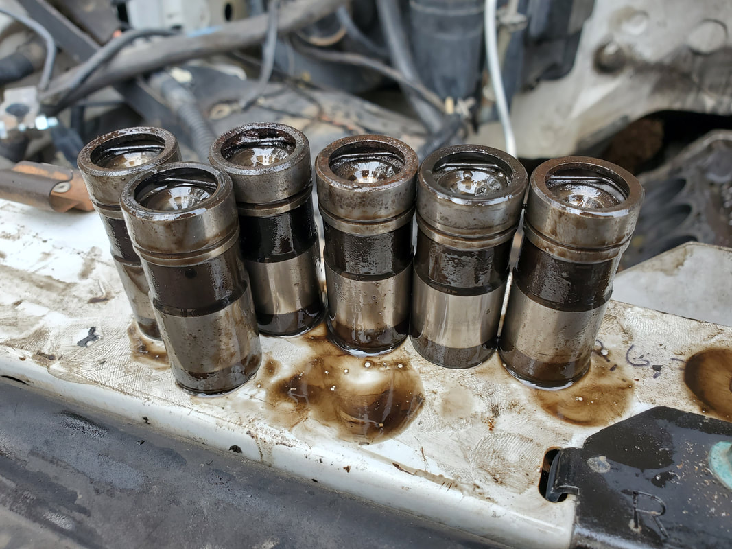
A batch of lifters that are more than likely bad due to the cores of these lifters not springing back up against the retaining clips. I can almost remove the retaining clips by hand with no assistance. This means the lifters are probably collapsing during operation, causing the running problems we've been experiencing.
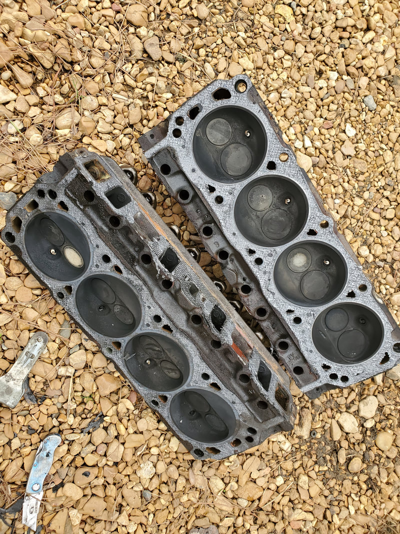
Cylinder heads after removal. Combustion chambers appear to be pretty good with only a minimum of carbon on the surfaces, nothing that would be concerning. I'll still replace these with the fresh set I have anyways just to be safe.
After getting my resupply of parts for the engine, I started back up on the work with reassembly. Going in reverse of the disassembly, I started with the cylinder heads. Since I already cleaned the surfaces of the block and the heads, I was able to get down to business. I put the gaskets down and installed the different set of heads, going through the motions with the bolts and the torque sequence. After getting the bolts torqued down properly, I moved on to the push rods and lifters. With their installation I torqued down the rocker arm bolts, securing the valve train. From there I moved on to the intake. I glued down the gaskets, which are four pieces, to the surface of the heads and the block, then mounted the intake manifold. I had to go through a series of tightening the bolts around and around, since on an intake, after tightening a bolt once, it can be come loose when an opposite bolt is tightened, so I had to keep going over the bolts until then were all equally tight. Once that was done, I mounted the carburetor, adding the choke cable, fuel tube and throttle spring. I moved on to the exhaust manifolds, bolting them down, and making sure to add the crane lift bracket and bracket for the oil dipstick tube. From there the flanges for the pipes were bolted up. With that I moved on to the accessory brackets. I was only able to secure two of the three bolts for each accessory bracket since the larger bolt hold in each cylinder head was somehow wide open with no thread. I'll have to use grade 8 bolts on these other two later in order to ensure that the brackets will stay on and not snap the bolts. From there I was able to attach the heater hoses, power steering hoses, alternator wiring, then the rad hose. Unfortunately, I didn't have a set of valve cover gaskets, so I had to put that off. I'll take care of the valve cover gaskets along with the mounting of the distributor. That will involve me using a remote starter switch to crank the engine over while holding a finger over the #1 cylinder plug port so when the pressure pops my finger off, I can set the distributor down where the rotor is pointing to the #1 wire on the cap. Once that's done hopefully the engine will crank up and not take much to tune and ultimately run like a damned sewing machine.
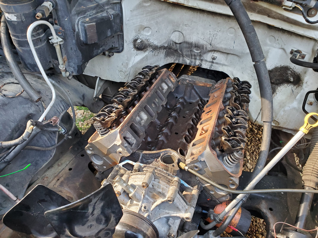
The "new" pair of cylinder heads bolted and torqued down onto the block.
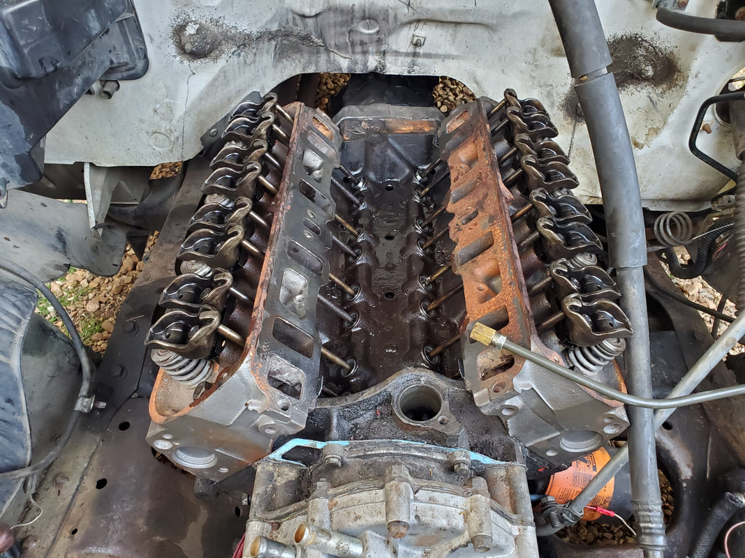
Push rods and lifters installed with rocker arms bolted down to proper torque. Now for the intake.
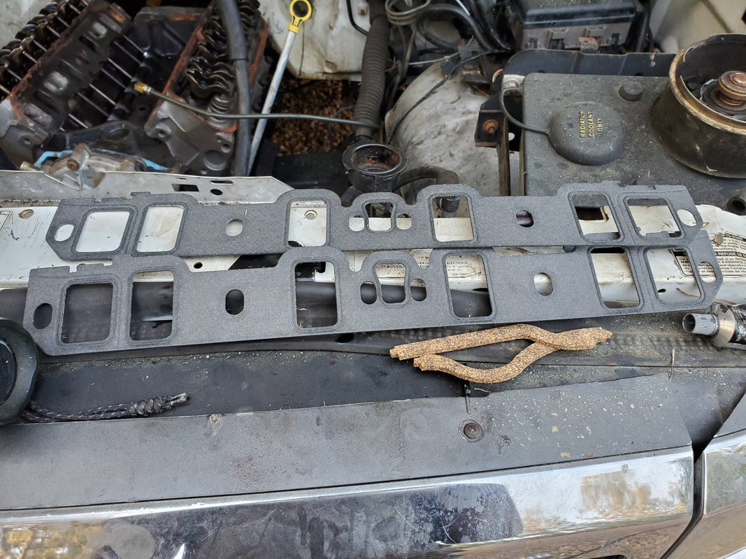
The intake gasket set, comes in four pieces, made to fit together so the gaskets won't shift and cause a misalignment and lack of sealing.
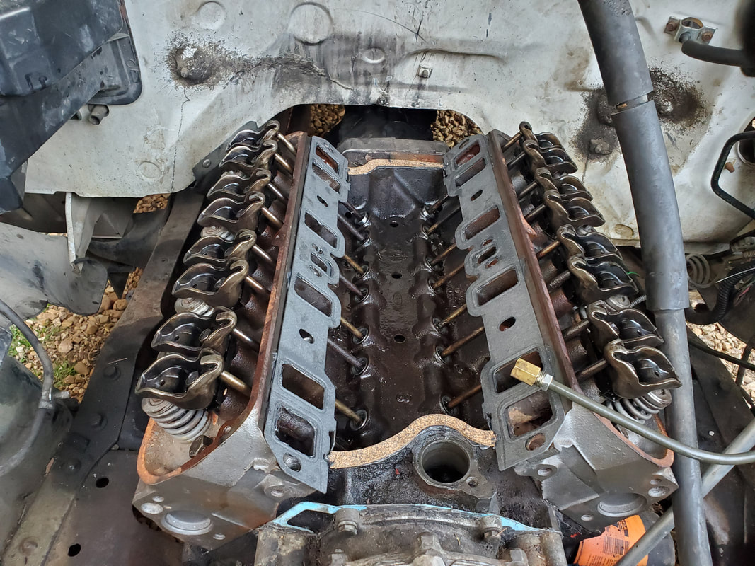
Intake gaskets glued down to surfaces of heads and block, note how the gasket pieces fit together via slots on the ends of the pieces.
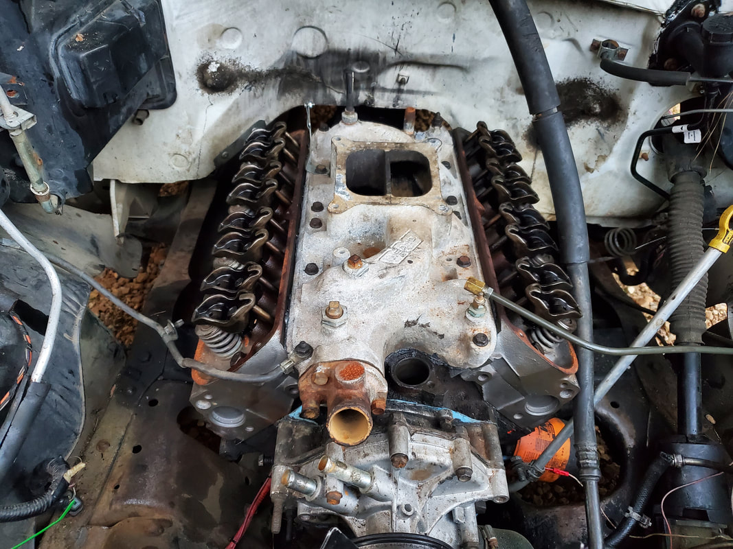
Intake manifold bolted down with bolts torqued to ensure sealing. Note the ground cable bolted to the front bolt on the intake. Also note the choke cable bracket bolted on the upper left of the intake as it sits in the pic (the right side of the intake).
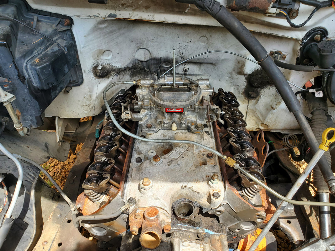
Carburetor bolted down to intake, with fuel line and choke cable attached.
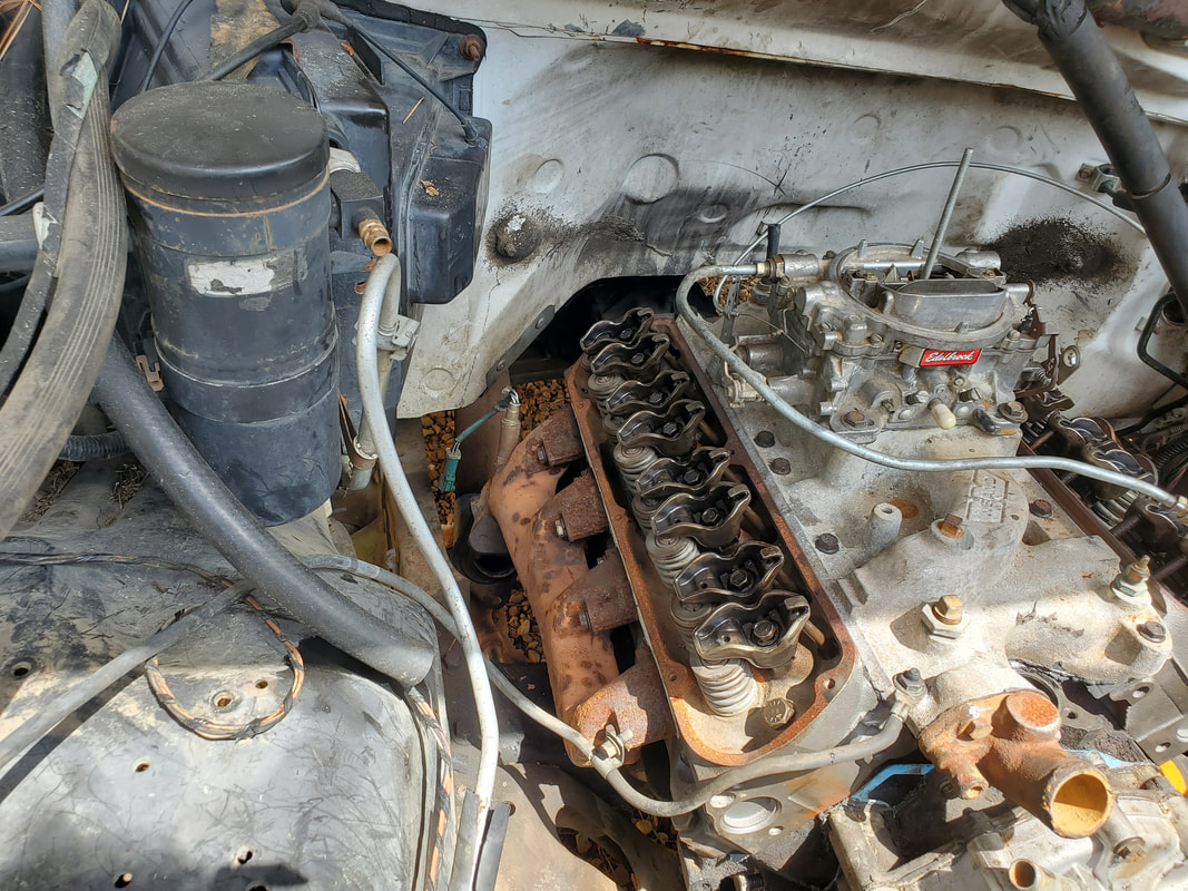
Right side exhaust manifold bolted down.
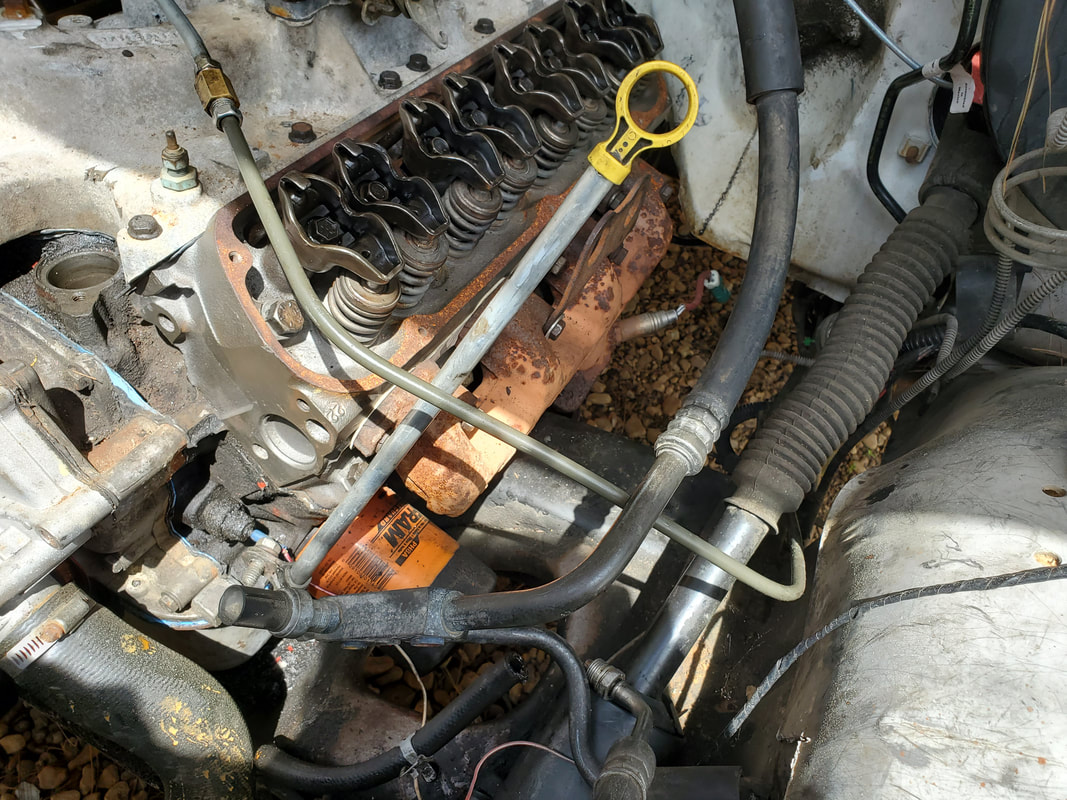
Left side cylinder head bolted down, along with crane hoist bracket and bracket holding oil dipstick tube in place.
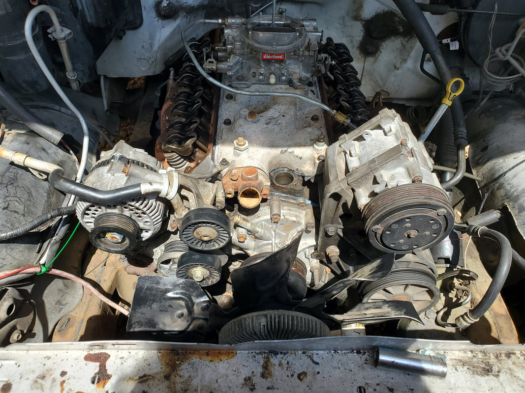
Accessory brackets bolted onto front of engine.
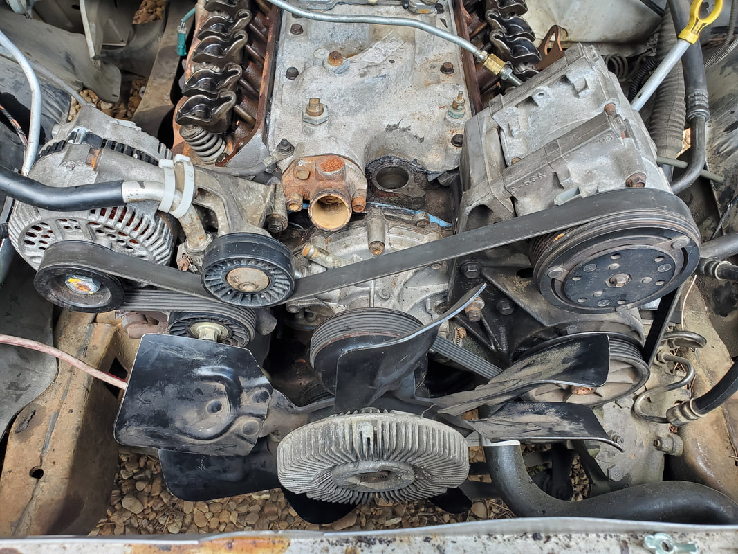
Serpentine belt mounted onto accessory pulleys, just before attaching hoses. Note power steering hose on bottom right secured in pump.
The next move now is getting the distributor in place. Doing this involves cranking the engine over slightly, using a remote switch hooked up to the starter solenoid while holding a finger over the #1 cylinder plug port. When the piston hits TDC, the pressure will blow my finger off the hole. With #1 cylinder being at TDC, I can set the distributor in place and where the rotor points is where #1 plug wire will go on the cap. Despite the previous placement of the wires, with the new placement of the distributor and rotor, the wires will have to be moved to coincide with this reality. With the plugs in place, I got all the wires situated. These generic wire sets are more than long enough that any wire can go to any plug with wire to spare. With the distributor down, I moved on to the valve covers. While working on the distributor, I had already glued the gaskets down so they could set and allow me to mount the valve covers without issues of gasket misalignment. After setting the valve covers down, the bolts went in nicely without any issues. I couldn't torque down the bolts since these stamped steel valve covers and cork gaskets can be warped and damaged with overtightening of the bolts. Later I'll probably install a pair of aluminum valve covers and composite gaskets which are more forgiving of over torqued bolts. Lastly, I secured the throttle cable, which involved removing an intake bolt to secure the bracket holding the throttle cable. Once that was secured I put the tip of the cable on the bolt I placed on the carburetor throttle, securing the tip with the nut I left on the bolt. The hose from the brake booster was also secured to the back of the carburetor. With that, I can now attempt to crank the engine and try to get it started and tuned and hopefully running good.
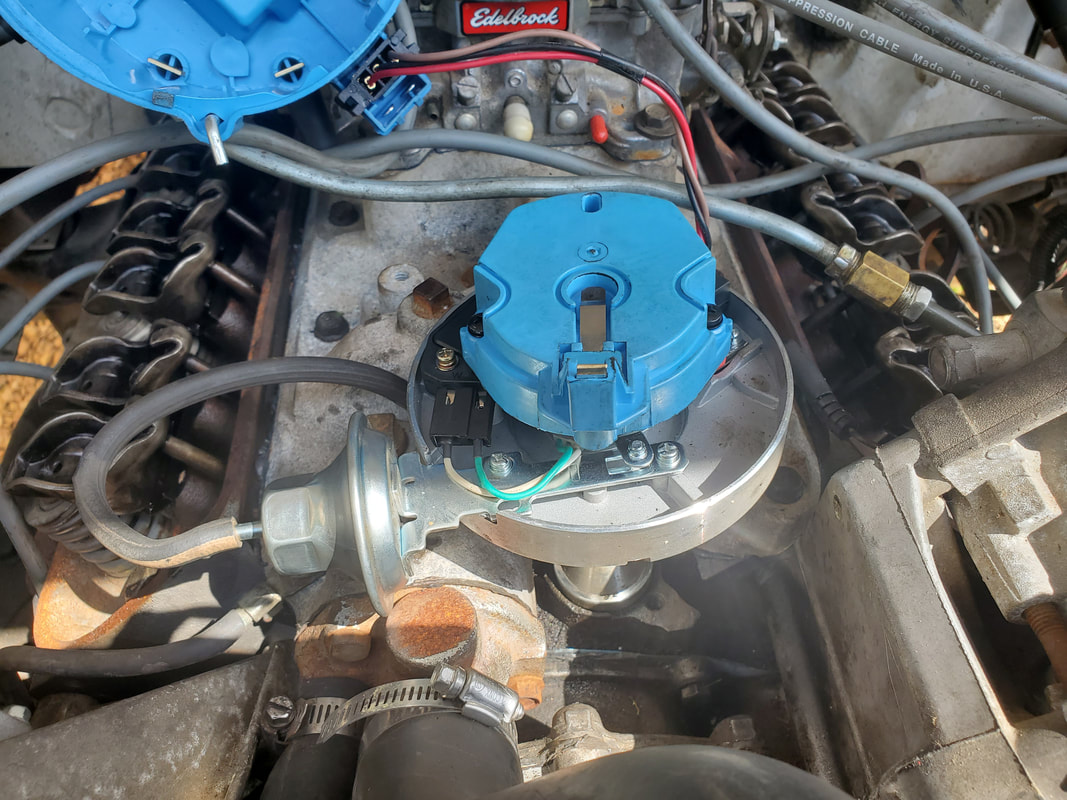
Distributor set in hole with rotor pointing to where #1 cylinder TDC is at.
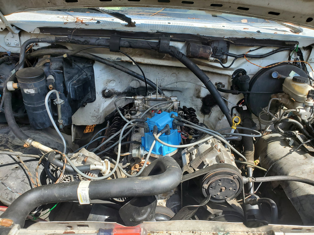
With rotor at new position for #1 cylinder, plug wires have all be moved around and snapped in place to the plugs, which are also in place in the heads. Note the excessive length of the wires.
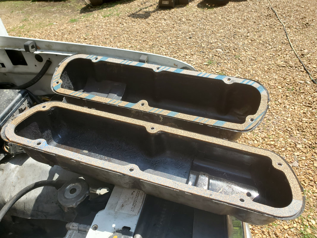
Valve covers with gaskets glued down and curing while I was working on the distributor. These are ready for installation.
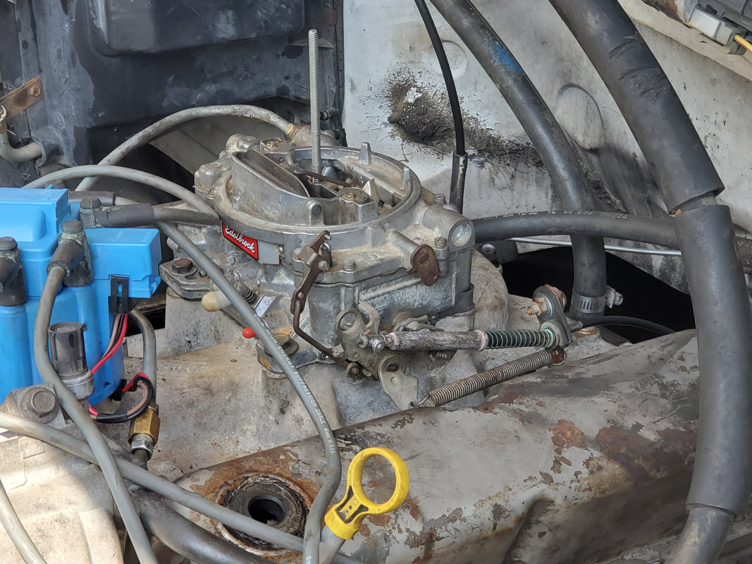
Valve covers are bolted down. Throttle cable and bracket are also bolted down and secured to the carburetor. Also note the large hose coming from the brake booster, plugged to the rear of the carburetor at the right in the pic.
After getting everything reassembled, I started the truck up again, going through the same motions. I ended up finding out that things were pretty much the same all over again. The engine ran, but it ran somewhat poorly, just like before. There was no difference, even after all the work that was done. My final conclusion was that the carburetors I was using were all bad. Even though I rebuilt them using the standard carb kits, the bodies needed to be thoroughly cleaned where the fuel and air passages were able to be blown out. What this ended up meaning was that I will have to install a new virgin carburetor if I want to prove my theory that the whole problem here was with the carbs.
I ended up sourcing a new generic Edelbrock online that was a mirror image of the 1405 carb we're working with. I was able to get this carb for a little over $200 at the time (despite the price going up to near $300 at this time), despite a genuine Edelbrock going for $100 more. With this new carb in hand, I swapped out the old with the new and got everything hooked up and ready to go. Another thing that I had to do was replace the starter on the truck. The new starter I put on happened to be for an automatic transmission. This physical difference in starters had the auto tranny starter meshing its drive gear with the flywheel all the time. While the starter would still crank, once the engine started, the flywheel was spinning the starter's drive gear, eventually wearing it out if allowed to continue to run. Luckily, I had a spare manual transmission starter, pulled from the same junkyard truck we got the extra manual transmission. I swapped out the starters before I cranked the truck again. A quick crank up had the engine firing up fast, almost effortlessly, with no issues with the starter tearing itself up. It didn't take much to tune the carb, even the vacuum gauge was already reading in the happy zone. I just tweaked the idle screws to the standard 1 3/4 turns and got the idle set by ear. I was able to test drive the truck with no real issues. I did have a couple stall outs only because the idle was too low. Otherwise, the tests were successful, I was able to shift up to 4th gear before running out of driveway and access road. The engine had a perkiness to it that wasn't seen with the other carbs. After my testing, I was more than satisfied that my theory was proven correct about the carbs. Next thing is the idea that my oil pressure and temp gauges weren't reading. I will probably do just a little troubleshooting before I just go get a couple aftermarket gauges and an A-pillar mount for them so I can hook those up and have working gauges so I can at least monitor the engine's vitals while I do more test driving.
One more thing that I took care of was repairing the broken back window. Rather than pull the entire sliding window assembly, I decided to replace just the one section of glass with a piece of plexiglass. I bent out the aluminum frame where the glass goes then got a piece of cardboard to make a template. Afterward I got a piece of plexiglass from a local glass place, which happened to be tinted (even better since the rest of the rear window is tinted), and used the template to cut out the piece for our window. After cutting out the piece, I was able to work the piece in place in the window frame and tap the bent out frame back in place around the plexiglass to hold it in more snug, even using some hot glue along the bottom to help seal and hold the plexiglass in even better and keep water from running down the bottom of the widow frame. I replaced a vertical piece of molding that went on the end of the plexiglass piece to divide it from the sliding glass. With that, the rear window was all fixed, sealing the cab once again.
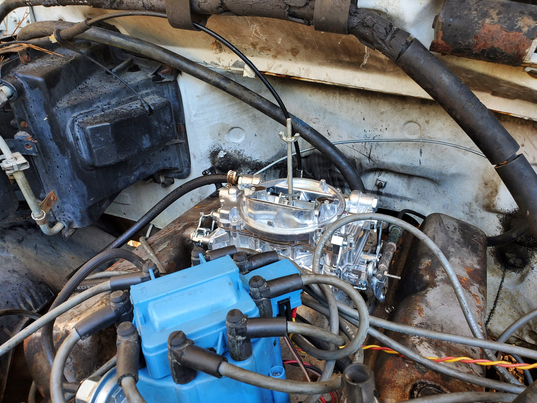
The new faux Edelbrock mounted on the engine in place of the old carb, we're ready to rock and roll now.
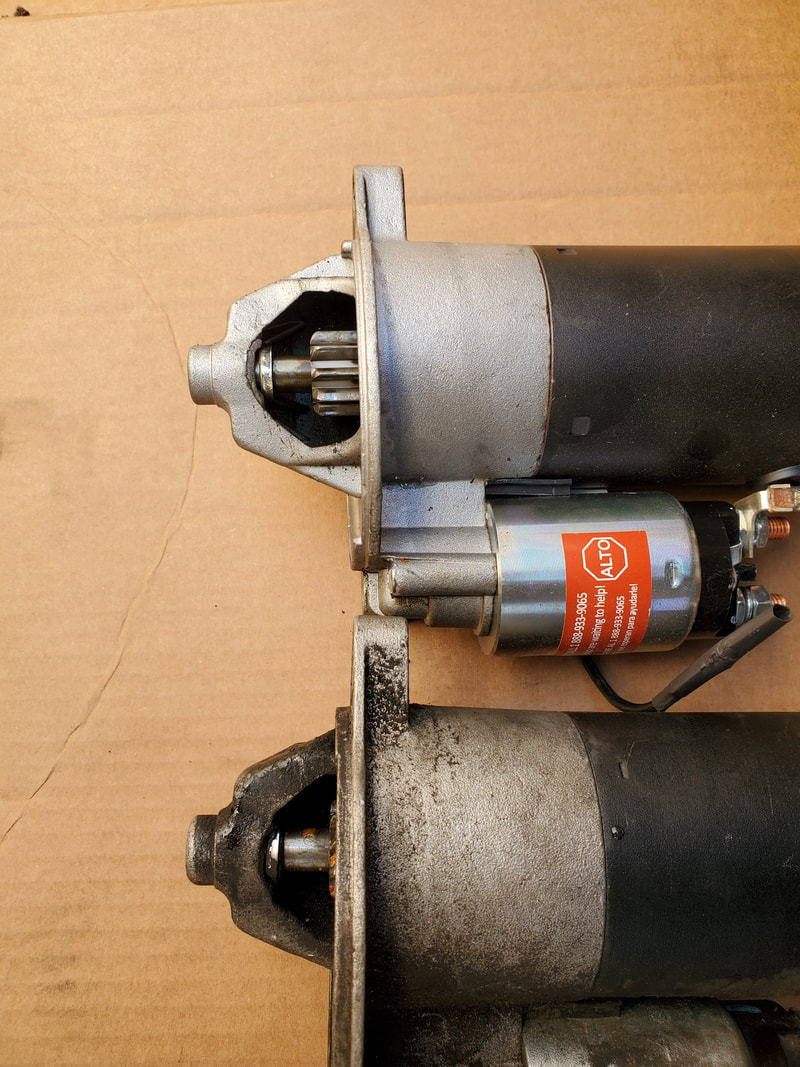
The automatic tranny starter (top) showing how the drive gear extends out from the body, right in the path of the flywheel gear, compared to the manual tranny starter, where the drive gear is recessed in the starter body in the standby position.
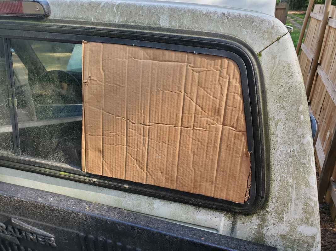
The cardboard template made of the broken back window prior to cutting plexiglass.
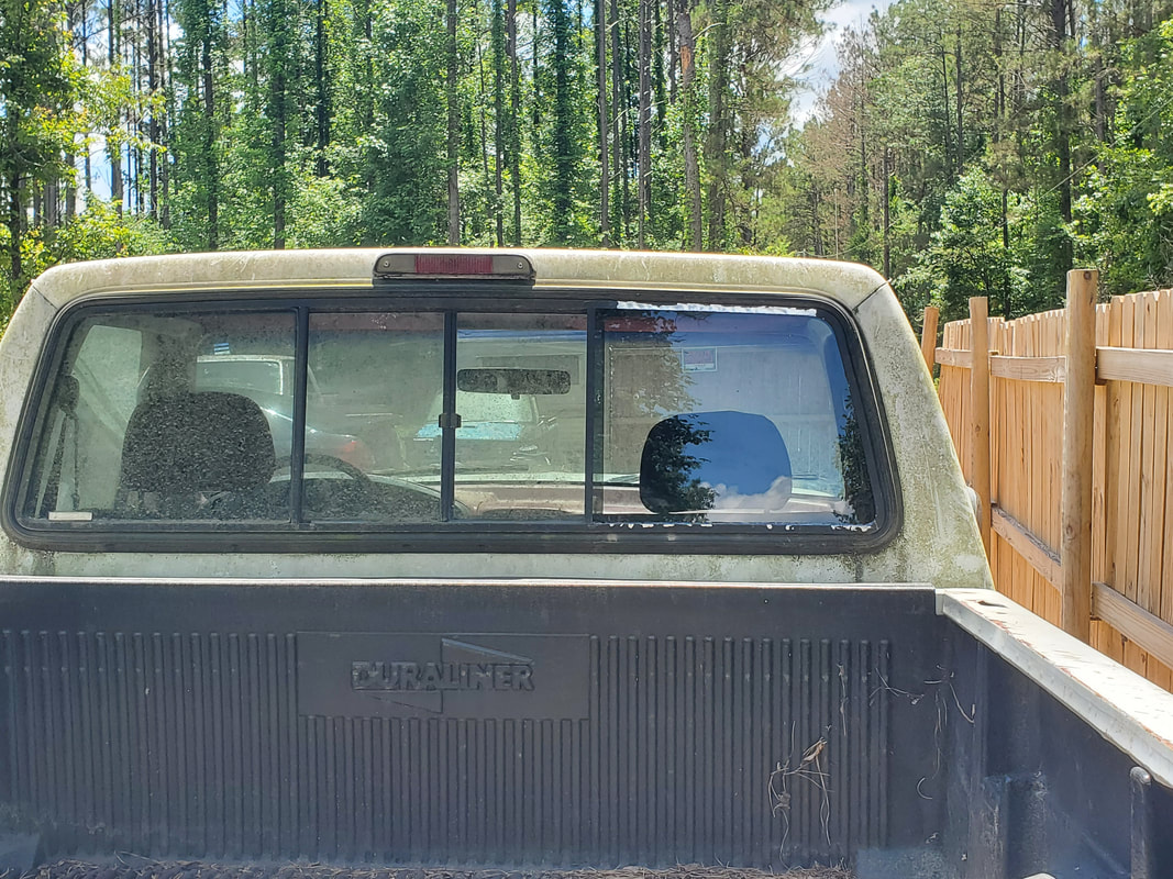
The new plexiglass window pane installed, as shown by the paint chipped frame section that was bent out to help in seating the plexiglass. Note the vertical molding piece installed on the let side of the plexiglass. Hot glue helps seat the bottom of the plexiglass to keep water from running down between plexiglass and frame. Barring the rest of the dirty window, this replacement glass fits right in with the same level of tint.
The next thing that I felt I had to do on the truck was add some kind of functioning gauge system. The stock gauges on the dash are not accurate to say the least, so rather than keep guessing on what the engine temp is or oil pressure, I went on the hunt. I could've went with the standard three gauge panel that typically bolts under the dash but this tends to be tacky in some applications so I kept looking. I discovered an LCD multi-gauge display unit, fresh from China, that reads voltage, oil pressure and water temp, and fuel level. Since this unit is straight out of China, measurements are in the metric system so oil pressure is in Mpa (whatever the fuck that is) and water temp is in Celsius. That's fine because the gauge also has a bar gauge in addition to the number measurement so one who isn't well versed in metric can just look at the bar gauge to see where they stand. I had to find a suitable spot for the gauge that would be more temporary than anything, run the wires down through the dash and into the engine bay, swap sensors neaten up the wire runs then hook everything up. Of course the last thing is testing by running the engine to see if everything is reading.
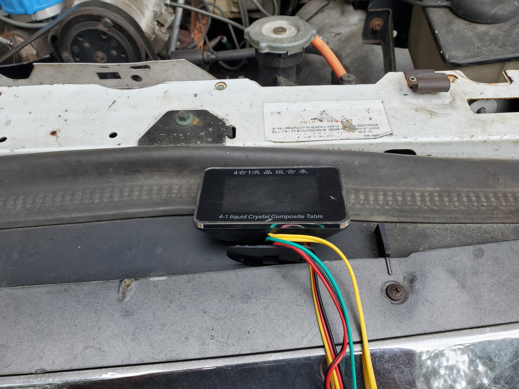
The Chinese aftermarket LCD multi-gauge unit.
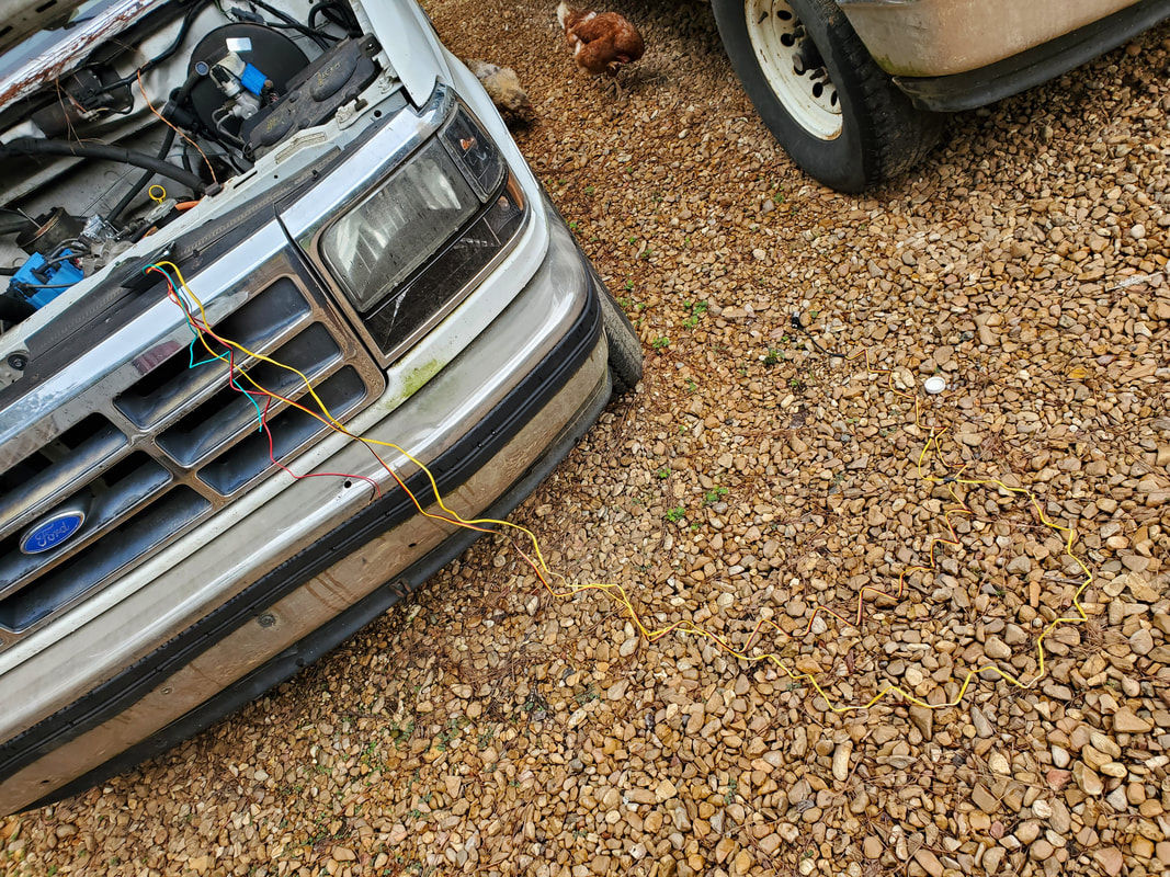
The super long wiring that is part of the gauge unit. More than enough wiring is provided to ensure wires can be run from the cab to the engine. The gauge comes with an oil sensor and temp sensor.
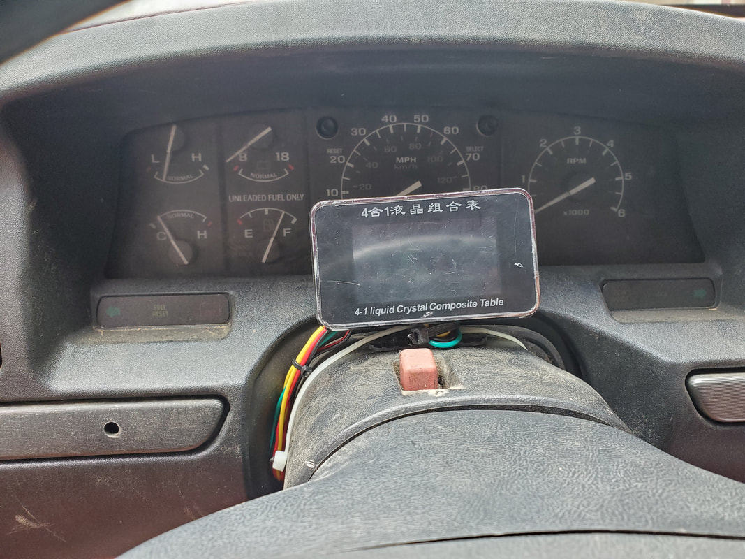
To keep from drilling holes in the dash to mount the base of the gauge, I used zip ties to secure the unit to the top of the steering column. The wires are tucked under the dash panel between it and the side of the steering column, then routed under the dash.
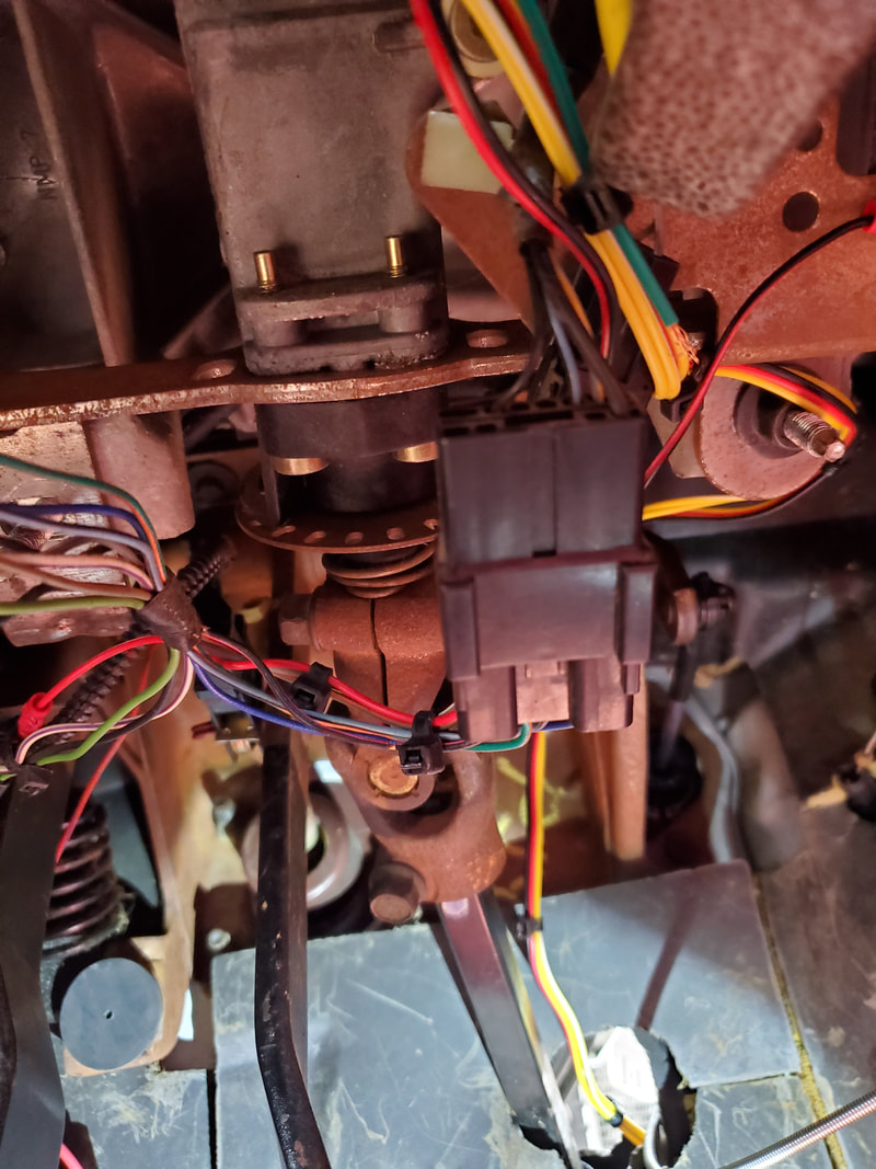
Wiring was bundled up and secured with zip ties every few inches. Wire bundle was routed and secured with zip ties along routes of stock wiring and routed out through a hole in the firewall where the steering column passes through.
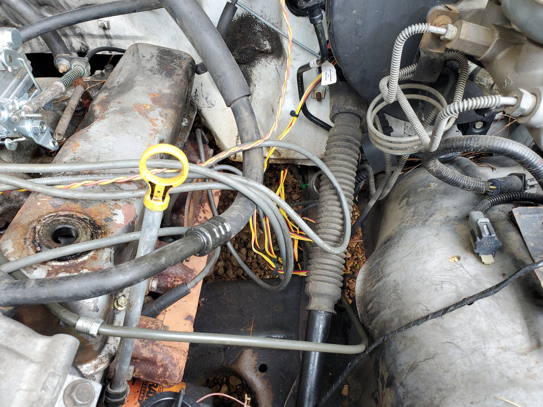
Excess wire bundle outside the firewall, prior to routing it around the engine bay to their respective sensors.
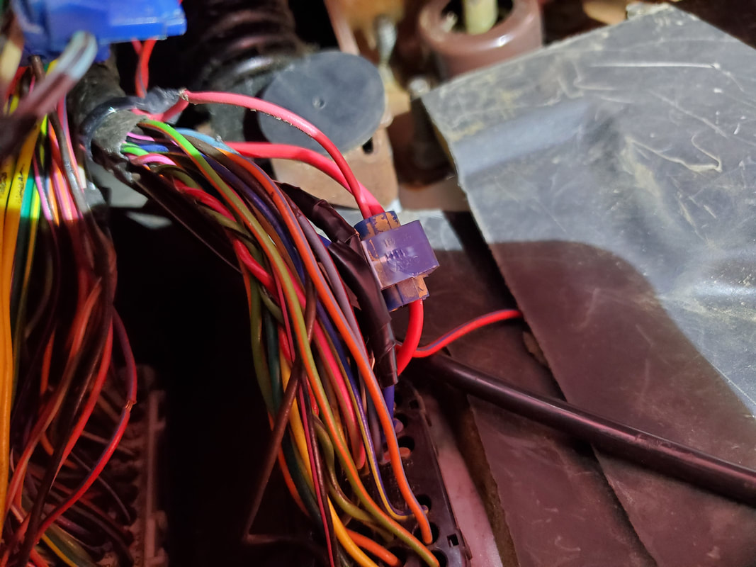
I took time to meter out a switched 12v power line in the stock wiring. I used a splice to tap into the wire to hook our power wire up to, then used an existing ground point to hook up the ground wire.
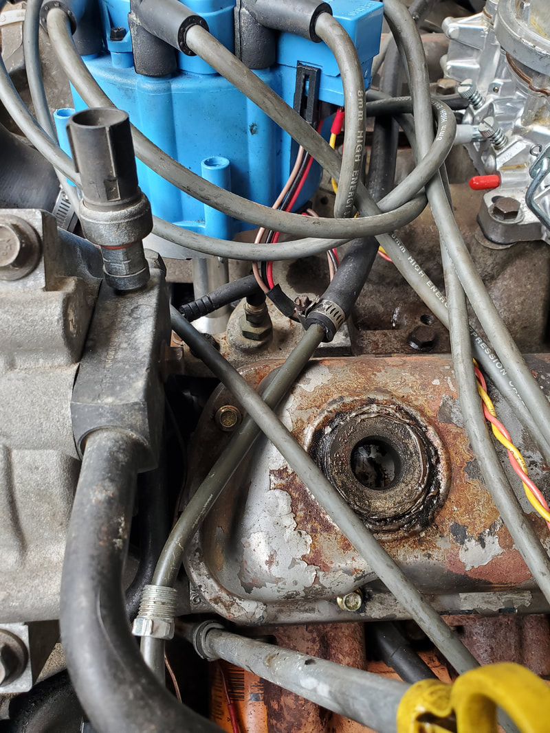
Stock temperature sensor, located under the distributor so it'll be relatively easy to remove.
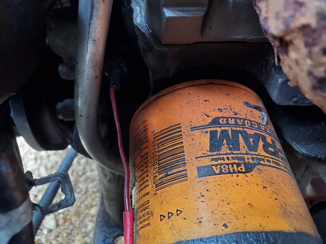
Oil pressure sensor, tucked away just above the oil filter and behind the dipstick tube, as noted by the single wire passing into the shadows.
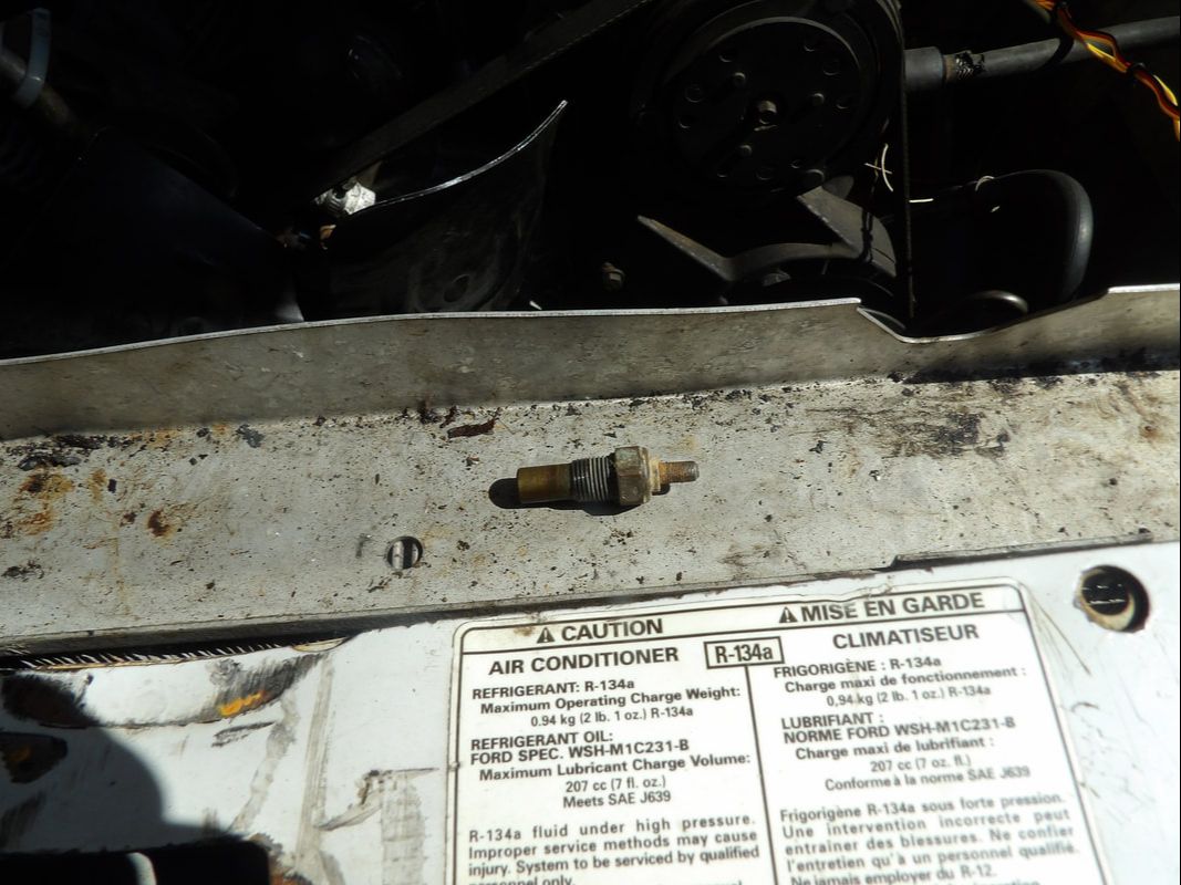
Temperature sensor after removing from engine.
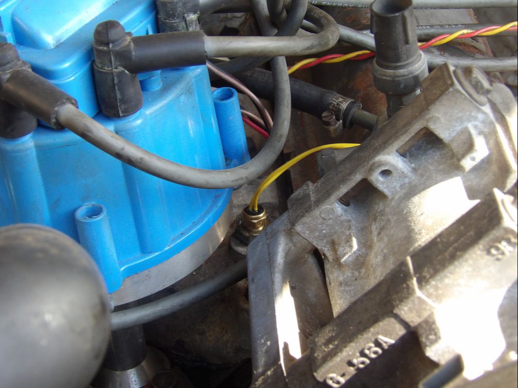
New temp sensor secured in place, note the pigtail on the sensor that will be plugged to the respective plug on the wire bundle.
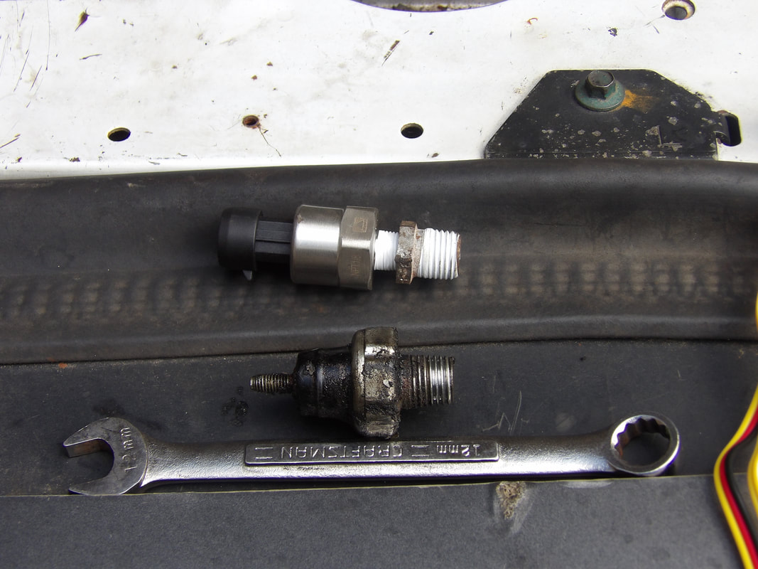
Stock oil sensor next to new sensor. Stock sensor is 1/4" NPT thread while new sensor is 1/8" NPT. I had to use a 1/4" to 1/8" adapter bushing to allow me to use the new sensor on the engine.
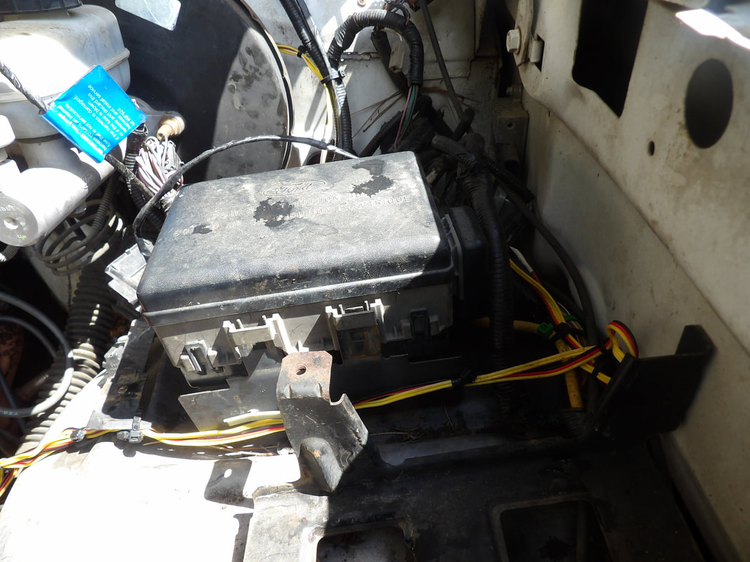
Wire bundle was routed up behind the brake booster and over to the driver's fender. The wire bundle was then routed along the same path as the stock wiring, zip tied along the way, around the fuse box and straight right towards the engine.
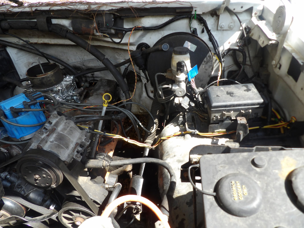
Greater shot showing wire bundle as it is routed and zip tied along the fuel tube as it comes up to the engine and the individual pigtails are routed ot their respective sensors.

Closeup of wiring where its zip tied to fuel tube, along with the pigtail going to the oil sensor. I had to remove the oil filter and the dipstick tube bracket to give me the space to remove the old sensor and install the new unit. Everything is put back in place here.
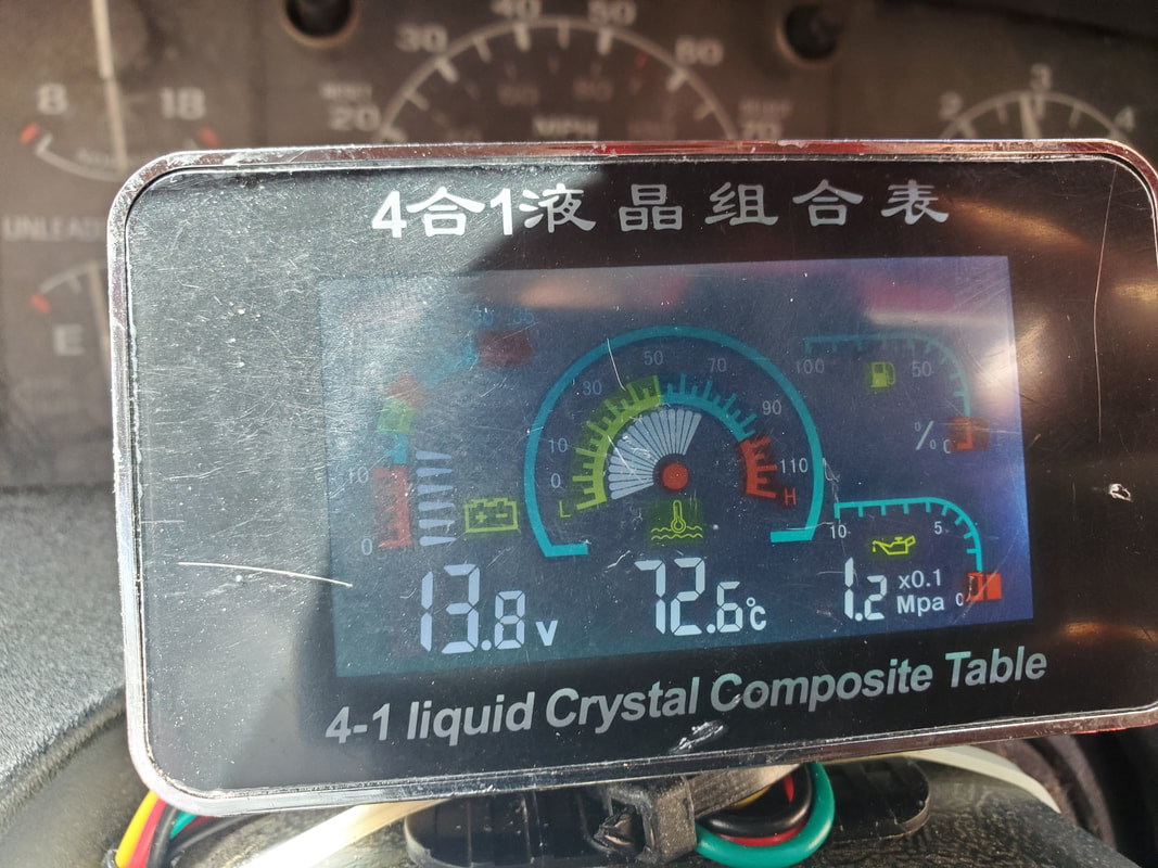
Gauge is online while engine is running, showing readings. Oil pressure was lower than most would be comfortable with but this would be somewhat expected with an old engine. Oil pressure wasn't low enough to dry out the top end. This unit is actually a self learning gauge for the fuel gauge where it can be set up with most fuel sensors to read properly, I'll have to look into hooking up the truck's fuel sensor to this thing to see if it'll read on this gauge. That will completely transfer truck monitoring to this aftermarket gauge. Even the voltage is reading, showing that the alternator is working as well.
Another thing that I took time to do was install the radio/media player that I picked up to replace the malfunctioning stock radio. This was an easy install as I also got the wiring harness that plugs into the stock harness to adapt the aftermarket radio to the truck. I also took a moment to try and get the fuel gauge to work on the multi-gauge cluster but that was a bust as everything I tried in terms of wiring did not work. Either the sending unit is bad or the gauge itself is a faulty unit. I'll have to address this later on, which might involve replacing this gauge cluster with a better unit. In the meantime I took a shot with the AC system and pulled vacuum on the system to see if it would hold. I also installed a circuit for the compressor with the wire coming from the point at the dryer pressure switch and blower motor where we got power from the AC switch. With that, I dumped some refrigerant into the system and in no time had cool air coming from the lower vent. I will still have to install a vacuum line going to the manifold on the HVAC switch panel so I can restore control of the blend doors to be able to get air moving at the top vents as well as defrost and floor vents.
The media player radio is installed after pulling the old radio and adding the wire harness adapter and mounting shell for the new radio.
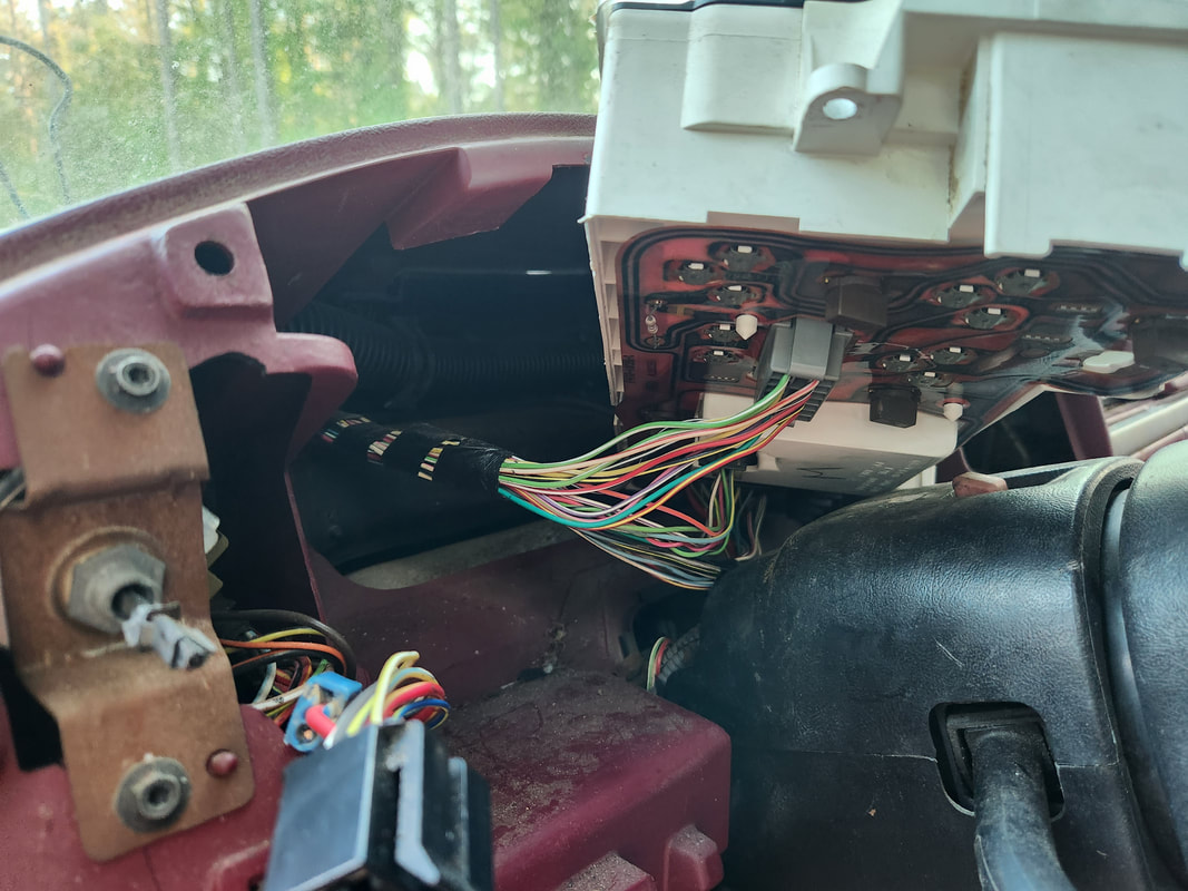
In an attempt to try and get the fuel gauge to work on the multi gauge cluster, I pulled the old gauge cluster out to get to the wires going to the old fuel gauge to try and make the new gauge work. This was a failure.
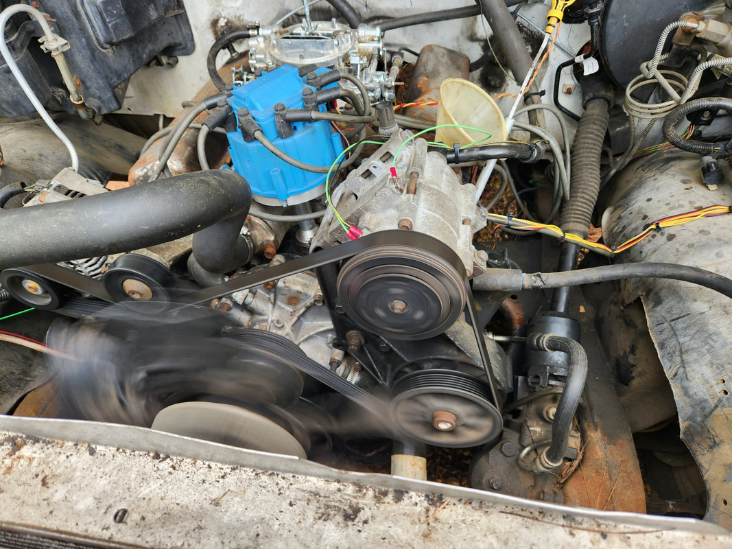
After pulling vacuum on the AC system, I charged up the system with refrigerant and got the system running. I also had to add a circuit for the compressor clutch by tapping into the old circuit that fed the compressor at the dryer pressure switch.
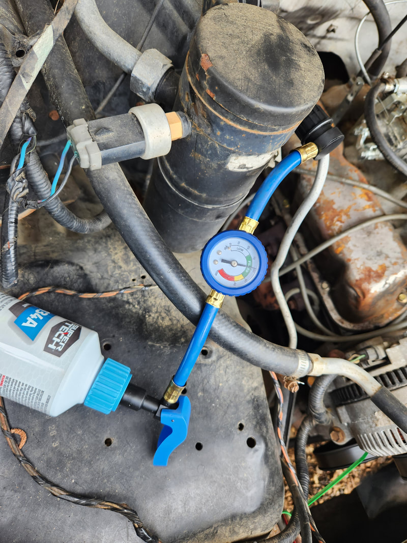
As the system runs and circulates refrigerant, more is added slowly until the system equalizes and maintains a decent pressure while running, as indicated by the gauge.
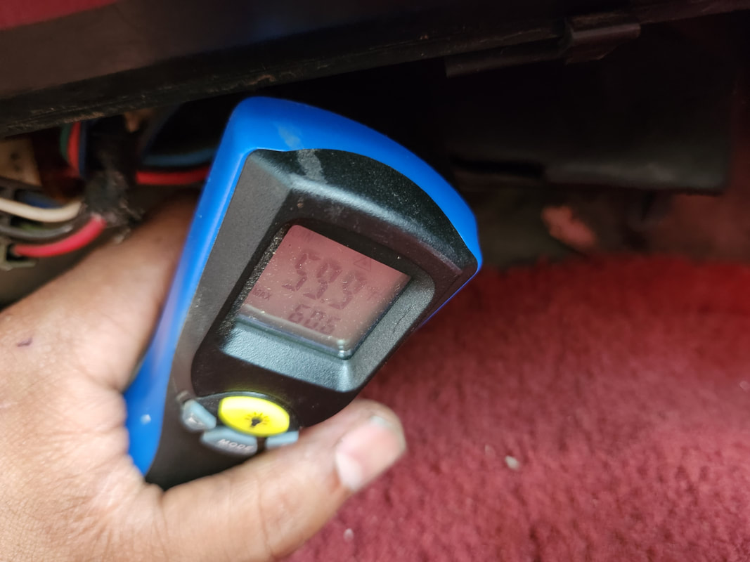
The temperature gauge reads 60 degrees when aimed at the outer housing of the HVAC box. Since the vacuum line that would go to the switch manifold to operate the blend doors is non existent, I could only measure the temperature of the HVAC box body. 60 degrees on the outside would indicate that the actual air being cooled is far cooler.
After not being able to get the fuel sending unit to read with the multi gauge cluster, I decided I would have to add an aftermarket universal sending unit. Since I didn't want to cut another hole in the fuel tank I removed the old sending unit and chopped it up, saving just the base and one of the fuel lines, then opening the base up to allow me to install the universal sending unit and weld in the fuel pickup tube. This way the modified sending unit is able to sit in the stock hole in the fuel tank while still being able to be hooked up to the multi gauge cluster. After some calibrations with the multi gauge cluster, the setting that best suited this sending unit was one where the gauge at full reads 63% and when at 1/4 tank would read 0%. While this might not seem like the best option, the way I look at it, the gauge will gradually drop from the 63% number as fuel is used and when it hits 0%, I can at least rest easy knowing there is a reserve amount of fuel still present so even if I feel adventurous enough to run the thing to 0%, I still have enough juice to run to a petrol station.
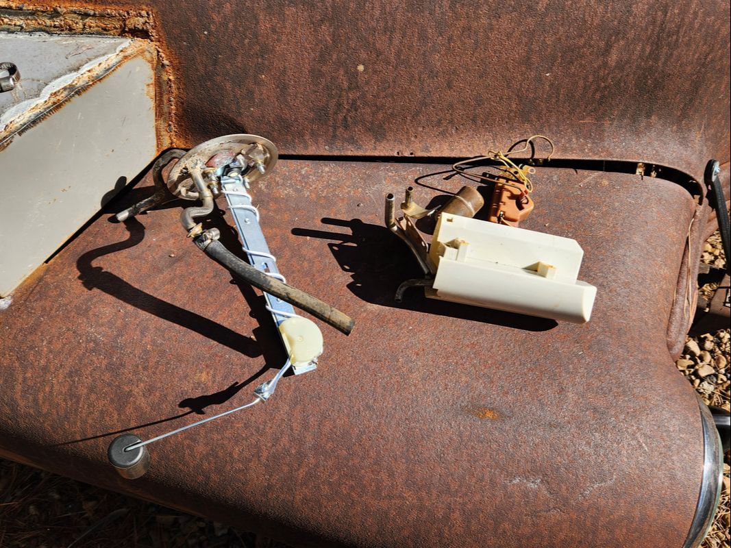
Hacking up the old sending unit had me cut the fuel pickup tube out with a rotary tool, leaving some of the metal around the tube so I can weld to that later after I drilled a new hole off center from where the new sending unit sits. The center was cut out using the rotary tool and holes drilled to accommodate the nuts and bolts that will hold the new sending unit to the base of the old sending unit. fuel tube had to be clocked where the output pointed forward when the base is installed on the fuel tank prior to welding.
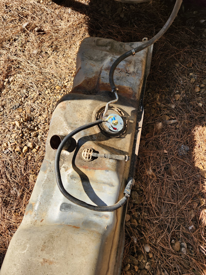
With the modified sending unit installed in the fuel tank, the output points forward where there won't be any kinks in the fuel hose. The wiring harness is wired up with the positive wire hooked up to the terminal on the new sending unit and the ground wire hooked up to one of the mounting bolts for the new sending unit.
