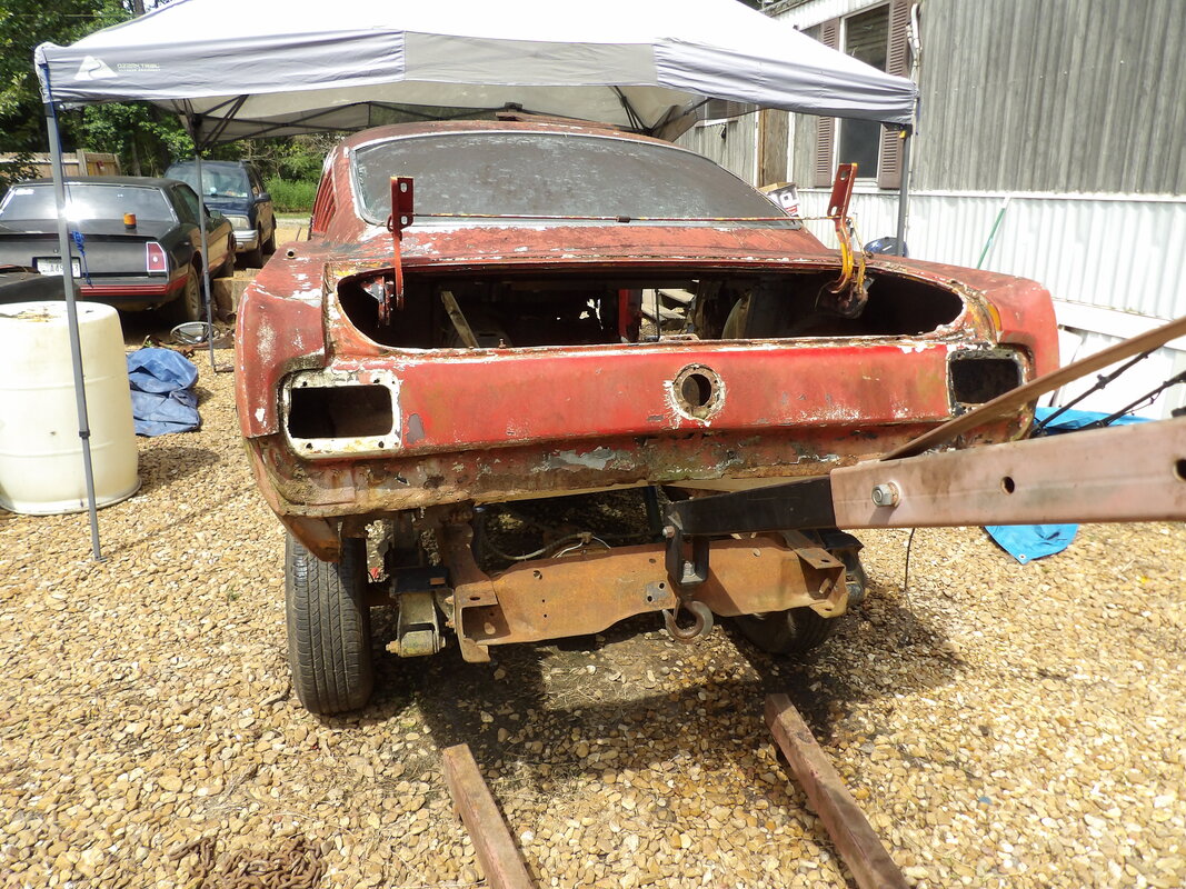
1965 FORD MUSTANG TRUCK FRAME RESTOMOD
AKA THE TRUCKSTANG
AKA THE TRUCKSTANG
Preface:
Since the days that this car was in IL and I had started working on it, the years have passed with very little done to the car as a whole. I did manage to do the typical engine/transmission overhaul, with the added bonus of installing some power mods to the engine in the form of a Duraspark ignition system, high lift cam, headers, larger dual exhaust, Edelbrock Performer 4bbl carb and Holley high flow electric fuel pump, performance 4bbl intake and even a higher voltage coil from a newer Ford powerplant.
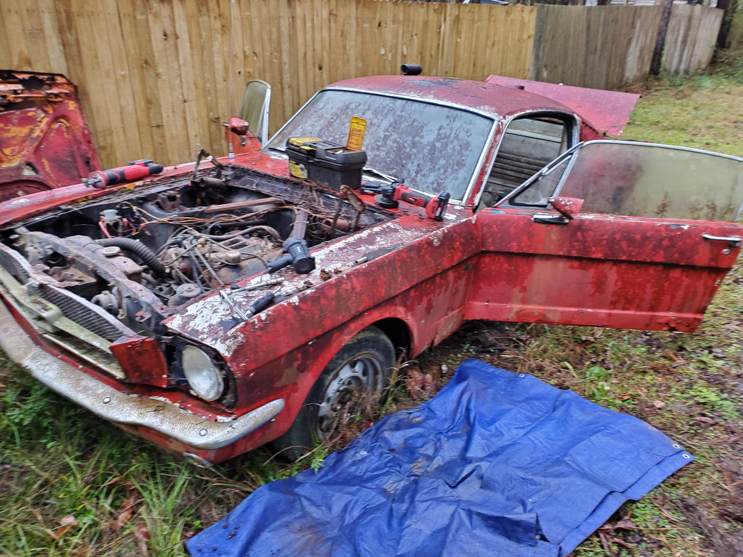
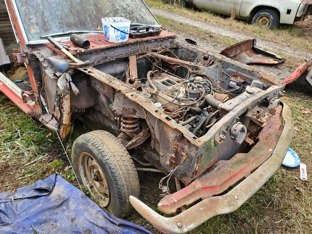
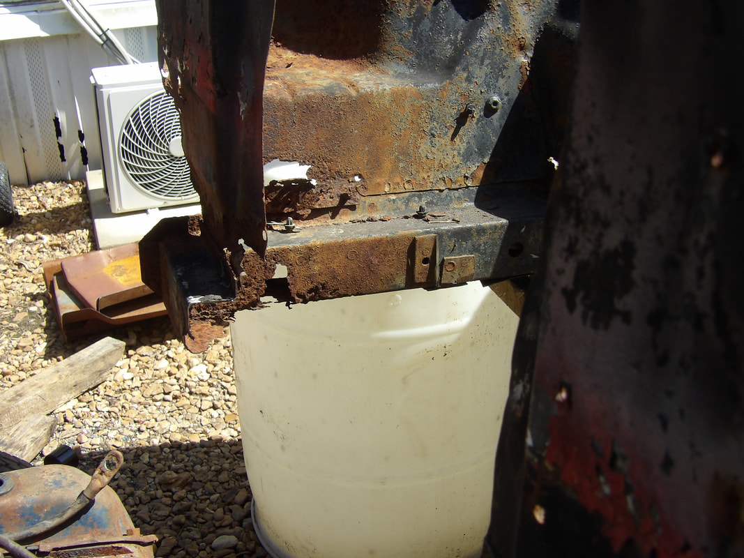
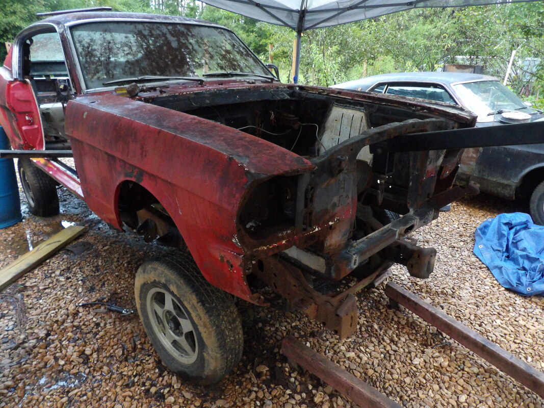
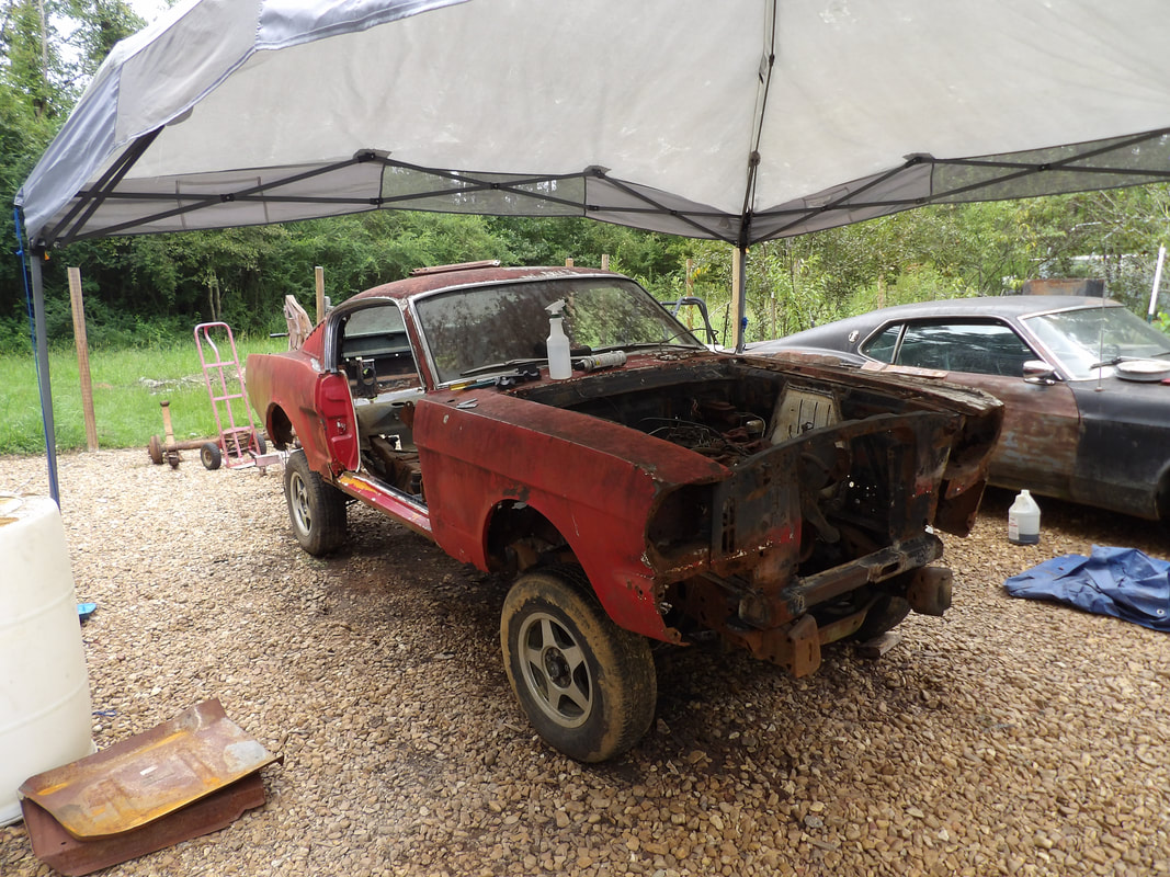
Even with the powertrain in good standing, the only things that were done to the car in the later years was minor patching on the frame and floors, nothing really serious, but from that point not much else was done on the car. It just sat for years, degrading in condition more and more until I reached a point where something had to be done before this car returns to the earth from which it came. I did put a battery on the car to verify that the engine still turned over, making me feel better that the powerplant did not freeze up. Oil also looked fine, no milkshake indicating the danger of water in the oil. At this point, I had to figure out a plan for this car since the body was in horrible shape along with the subframes and floors. The only option I had that would break the bank was to mount this body on a truck frame.
Since the days that this car was in IL and I had started working on it, the years have passed with very little done to the car as a whole. I did manage to do the typical engine/transmission overhaul, with the added bonus of installing some power mods to the engine in the form of a Duraspark ignition system, high lift cam, headers, larger dual exhaust, Edelbrock Performer 4bbl carb and Holley high flow electric fuel pump, performance 4bbl intake and even a higher voltage coil from a newer Ford powerplant.
Even with the powertrain in good standing, the only things that were done to the car in the later years was minor patching on the frame and floors, nothing really serious, but from that point not much else was done on the car. It just sat for years, degrading in condition more and more until I reached a point where something had to be done before this car returns to the earth from which it came. I did put a battery on the car to verify that the engine still turned over, making me feel better that the powerplant did not freeze up. Oil also looked fine, no milkshake indicating the danger of water in the oil. At this point, I had to figure out a plan for this car since the body was in horrible shape along with the subframes and floors. The only option I had that would break the bank was to mount this body on a truck frame.
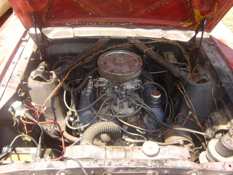
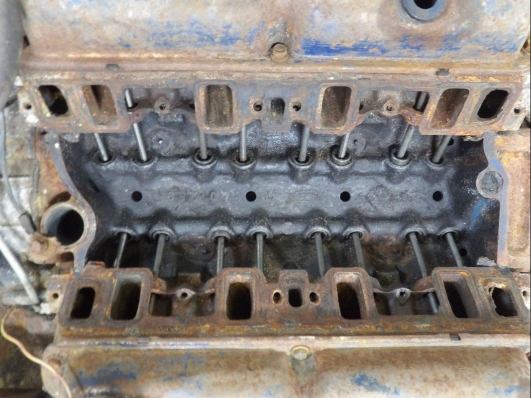
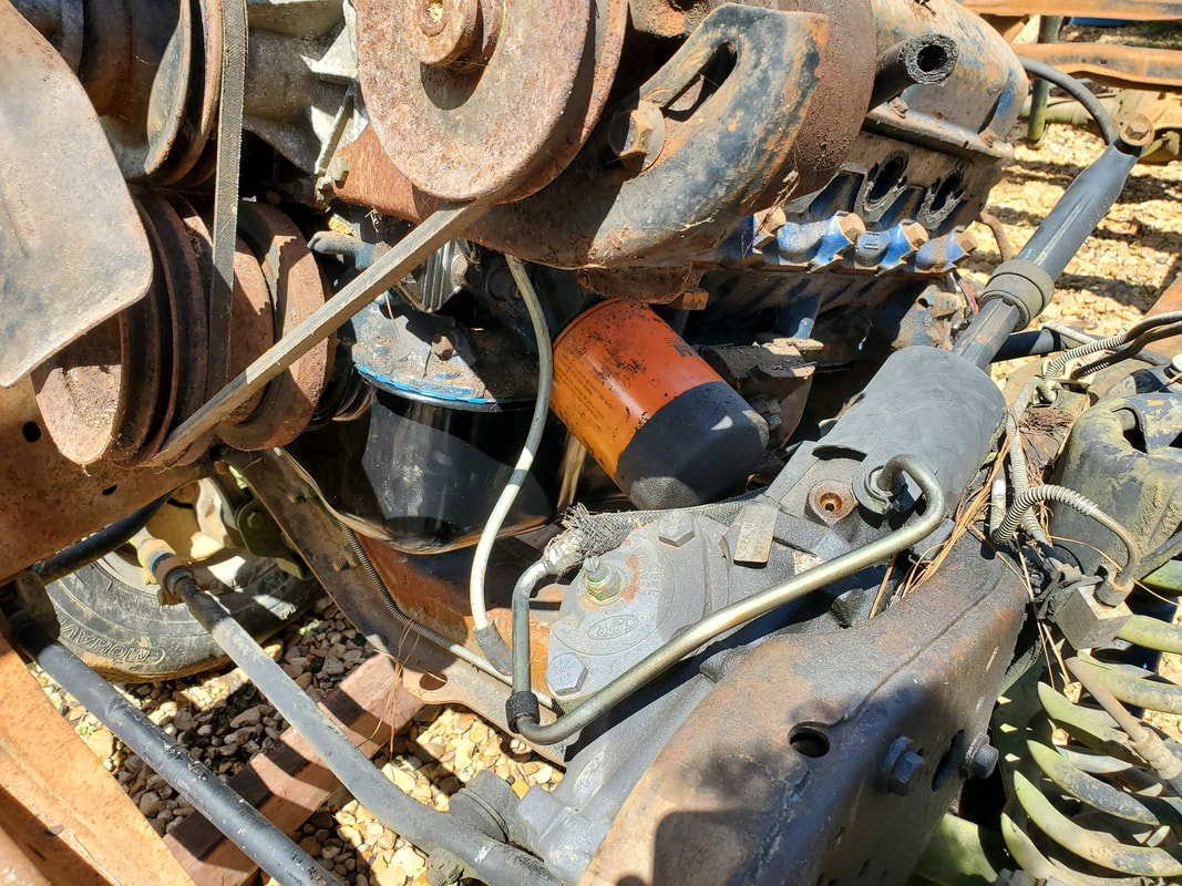
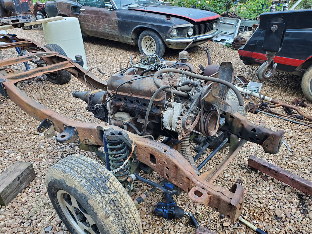
Shot of the 289 powerplant.
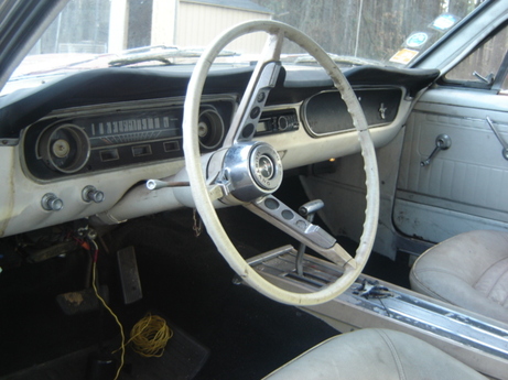
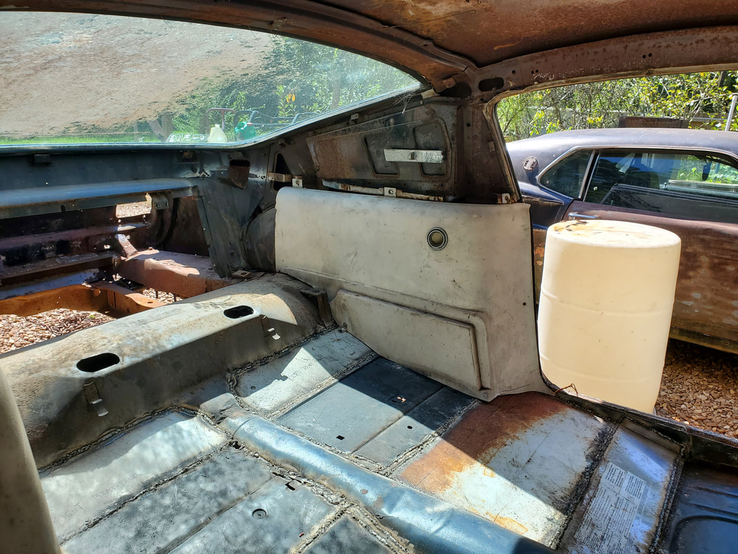
Interior of the car as it was back around 2010.
After doing some research, I found that this type of project was actually pretty common. It was more common with specific truck frames, like Bronco or K5 Blazer frames, based on the idea that many cars had the same wheelbase with these frames. I later found that the short bed/single cab Ranger frame shared the same wheelbase as the vintage Mustangs so this would be a logical start, given the idea that the frame is small enough that a build on this platform wouldn't have the vehicle looking too "trucky". There was also the idea that I was easily able to get my hand on a Ranger frame for pretty cheap, so this is where we're making our stand.
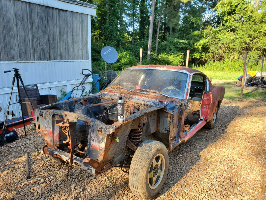
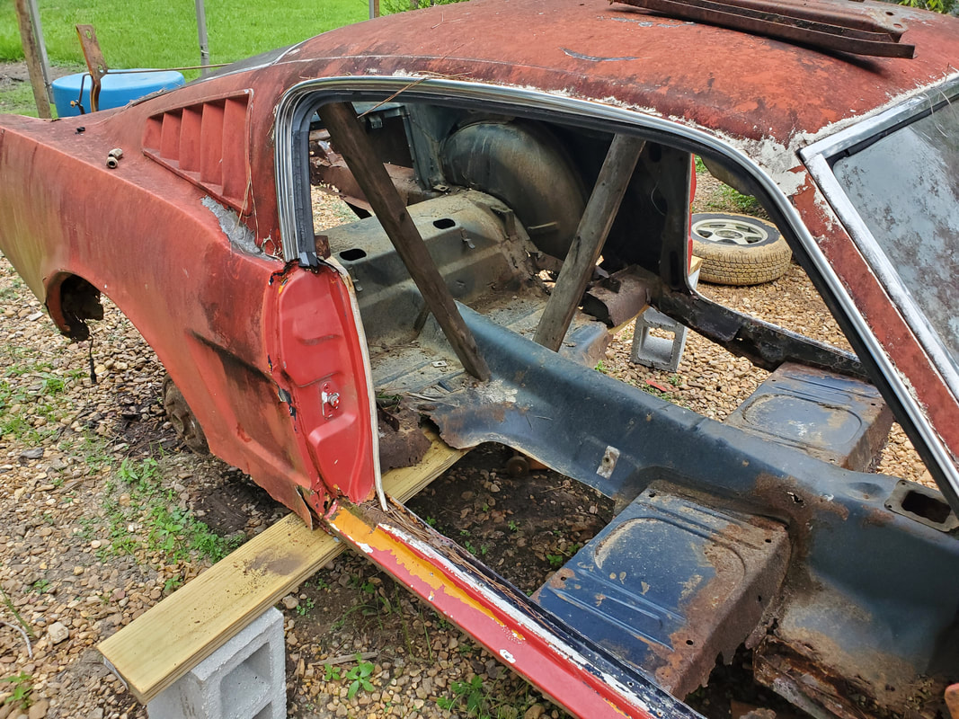
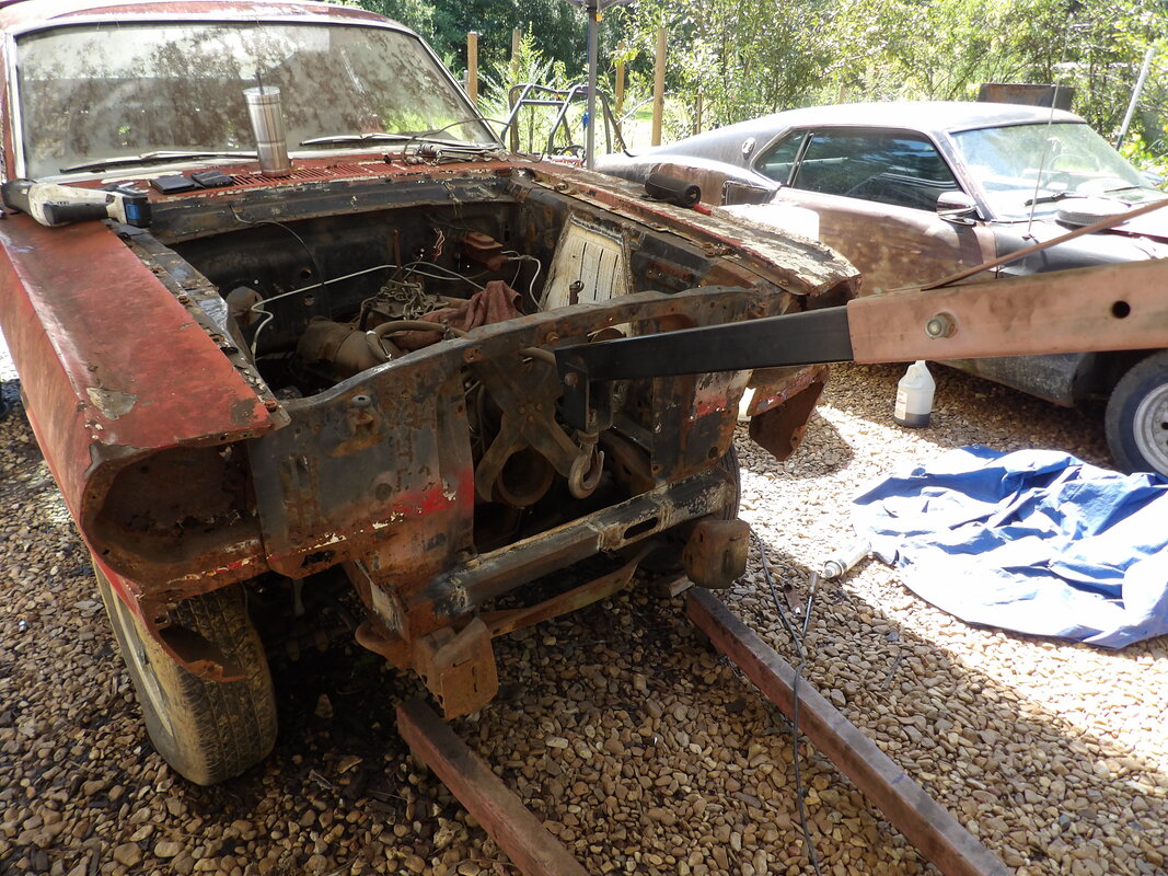
The first thing that would need to be done is strip the car down. This means everything has to come off of the unibody. This includes panels, doors, seats, gauge cluster, wiring, exhaust, everything. If its attached via nuts and bolts, it comes off. This will even include the front suspension and the rear end. To get ready to move on to the next phase of the project I have to have nothing left on the body but the body. Of course the first thing I did was pull the hood off, since I will be going in and out of the engine bay.
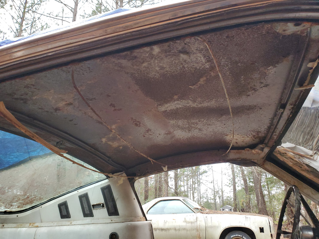
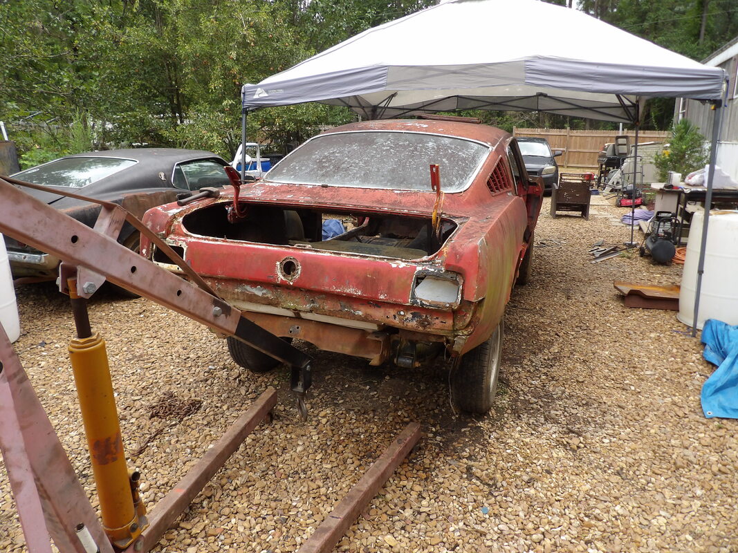
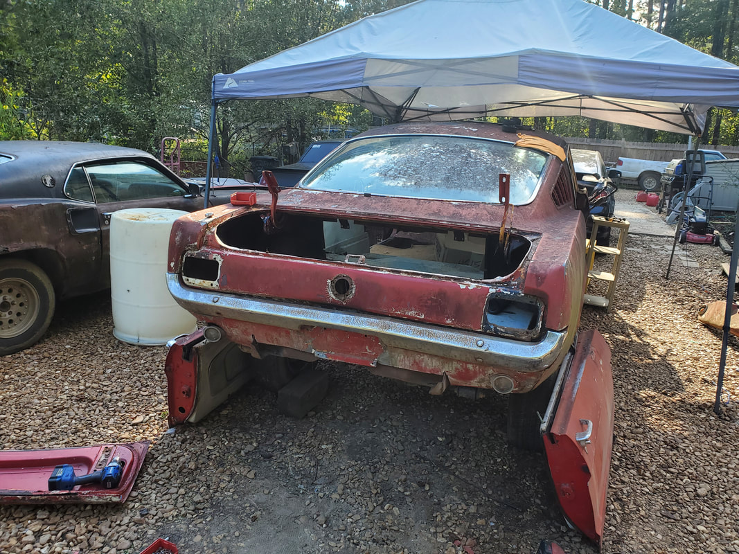
The Rustang after removing the hood. One can see the level of decay on this car.
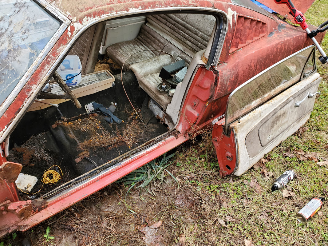
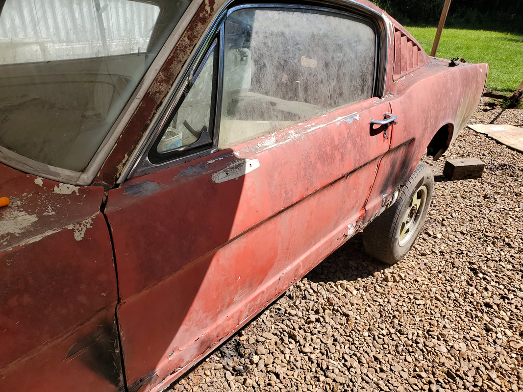
Door and seat removed from driver's side, note rust on inside of cab.
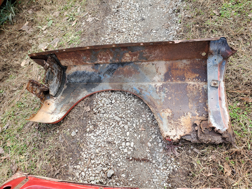
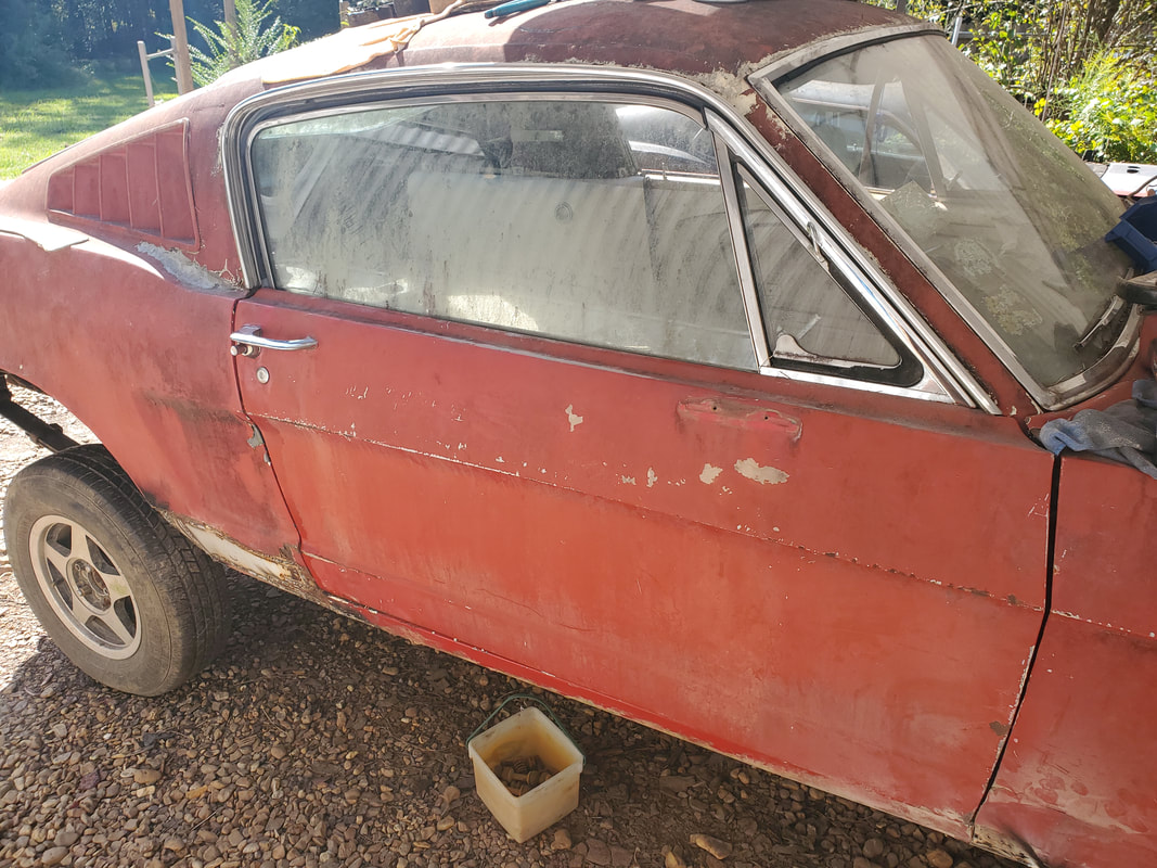
The next fun thing was removing the fenders. While one would think this shouldn't be a big deal, I never pulled apart a 65 Mustang so there was a learning curve here. While the bolts along the fender apron were no big deal and the couple of bolts at the bottom by the rocker panel weren't that big of a deal even when they had to be ground off with the angle grinder, it was all of the bolts at the front of the fenders that connected the extensions that held the headlight buckets and connected the grille panel and valance panels to the fenders. I had to fight to get some of these bolts free as they were recessed in nooks that required extensions and some finesse to get them turning to free them up. Eventually I did manage to get the fenders out, and by association, the valance and grille panels along with the headlight housings and grille, which came out in one piece.
Front end without fenders, exposing even more rust underneath.
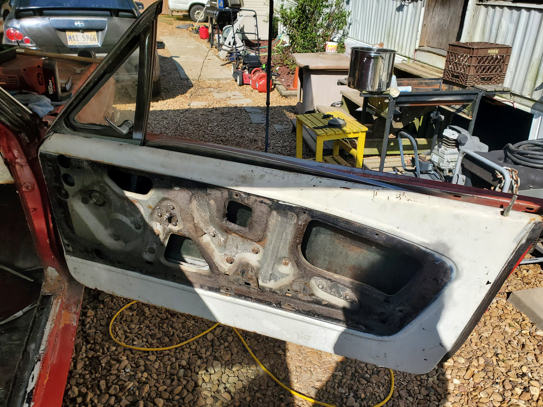
Like the other sketchy sections of this car, the seats were also going to be problematic. On these Mustangs the section of floor where the seats are mounted is actually a two part floor with the elevated section of floor being where the seat frames are actually bolted to. This means that there's holes in the outer/lower floor for a socket to go through to reach the nuts on the studs of the seat frame. As with everything else on this car, most of these nuts were rusted badly. After a while I ended up having to pull out the reciprocating saw and after some finessing I was able to cut the studs above the floor to get the bolts that didn't already come free. After some kind words and a little effort the seats were finally free. With the fenders off, I was also able to get the doors off easily.
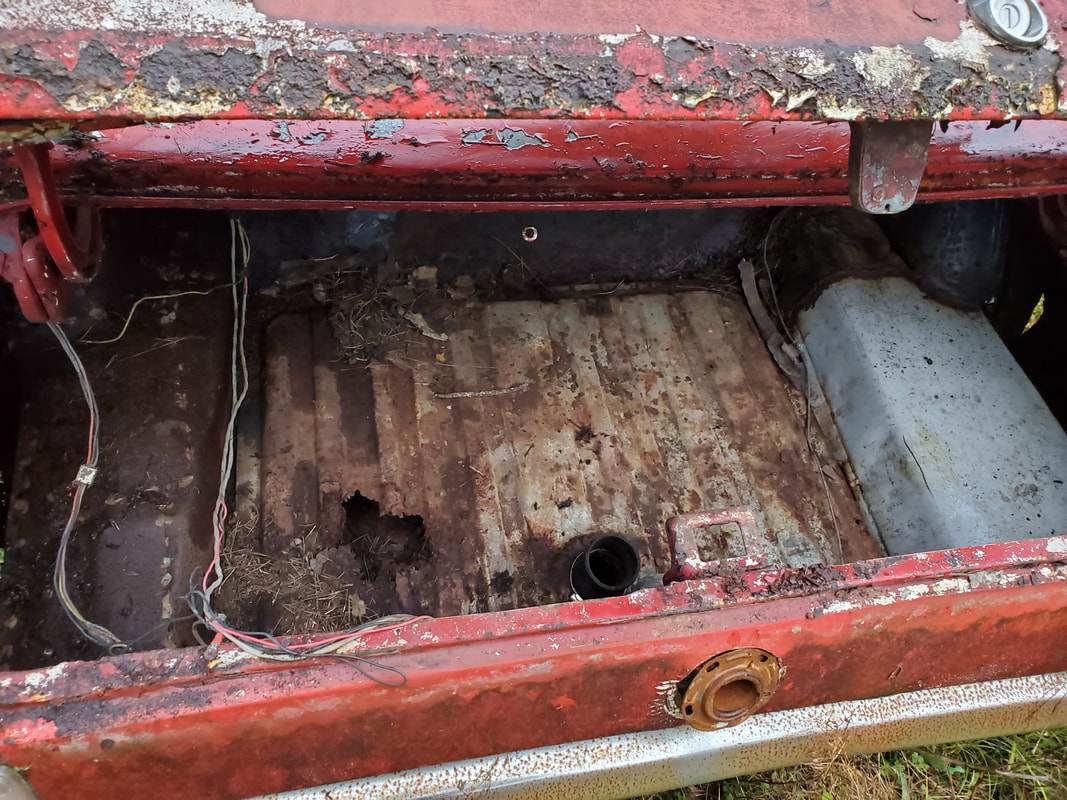
Going on a tangent, I moved to the rear of the car. I had to go ahead and pull the trunk floor and gas tank since these two components would be very easy to remove. The trunk is held in by a few bolts and the gas tank turned out to not even be bolted down at all, probably from when I had installed the tank before.
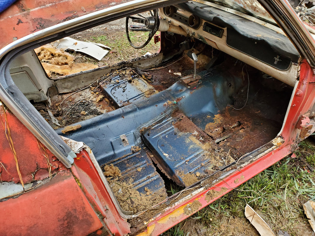
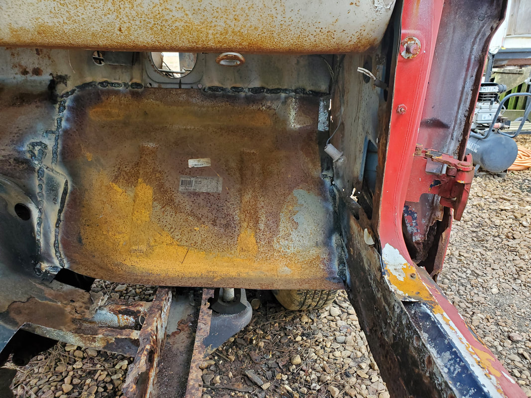
With the components pulled from the car I went ahead and pulled the carpet free. The carpet was covered in rat shit and dirt and grime. I wouldn't have reused this carpet even it it was completely solid due to the contamination of stuff in this material. Removing the carpet further showed the level of rust and rot in the car's floor pans.
While in the interior I pulled the headliner from the ceiling. Of course the material was ratty enough that it just tore free, leaving the rods that supported the material against the ceiling. With the headliner material gone and the rods removed I moved on to the side panels from the back seat.
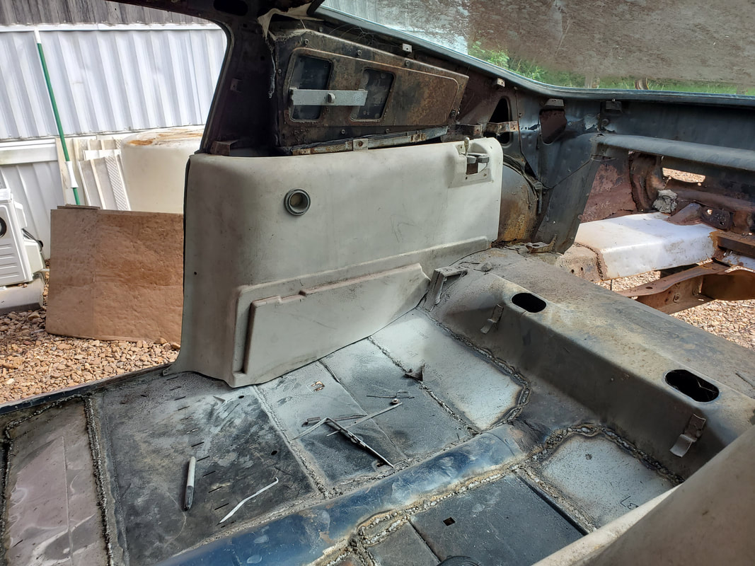
Interior completely free from interior panels. still has a lot of dirt and shit in place.
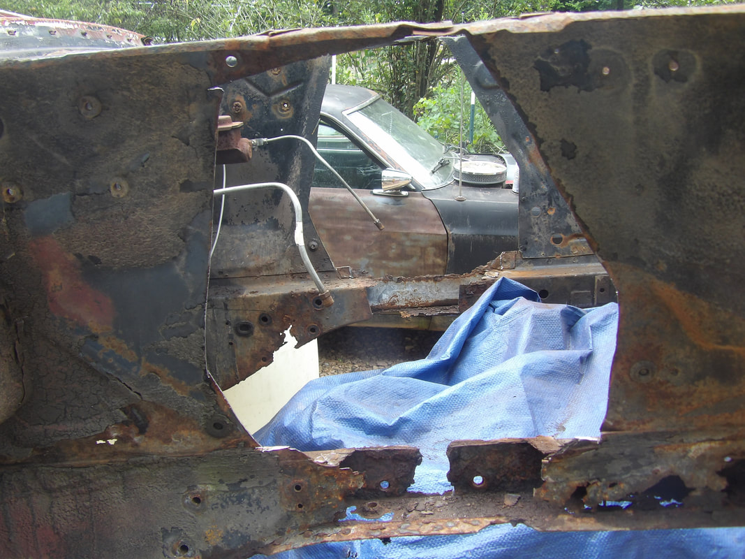
For a brief moment I moved back to the front to cut out the rusty splash panels that go under the fenders to keep water from being splashed on area by the doors and their hinges and the intermediate firewall panel area. These areas would've been rusted all to hell without these panels but because they were there, they were rusted all to hell instead. Because of the rust they had to go.
Moving along we go back to the rear of the car. Here I focused on removing the taillights and bumper. The taillights weren't really too bad. A couple of screws broke or were rusted away to begin with but overall after removing the screws that needed to come out, I had the taillights out. That was the easy part. The fun part was the bumper. Like the other rusty shit, the 1/2" bolts were rusty on the bumper brackets. These huge bolts were a PITA to get out since the angles that were needed to get the reciprocating saw or angle grinder in were not there. I ended up doing some extra chopping and grinding from the inside to try and knock the nuts free while also cutting into the brackets to eventually get the bumper free.
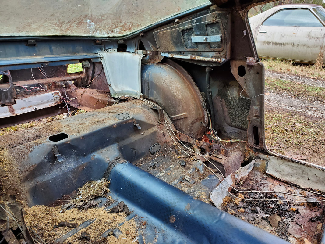
Going back into the interior I removed the gauge cluster and some miscellaneous moldings from around the dash as well as the wiring on the inside of the cab. I removed the wiring going all the way back to the trunk then moving back to the engine bay to finish up the wiring removal. With all the wiring out I moved on to the dash frame. This is where things got to be fun and enlightening at the same time. Looking all over I couldn't find what looked like any kind of mounting bolts or nuts or studs that would hold the dash in like on the 69 or 73 Mustangs. I looked and seen what looked like some kind of sheet metal screws under what looks like the dash pad, right under the windshield. I tried removing the dash pad, having to scrape the dash material away to see if it was covering some hidden screws that would allow me to remove the dash. After doing all of this buffoonery, I ended up stopping and doing some research. I found out that the all metal dash and frame in 65 Mustangs were actually welded in to the unibody on the inside and were NOT intended to be removed. If it needed to be removed, one would have to break or drill through the spot welds to free up the dash. What did that mean for me? The dash was NOT coming out.
The next thing was the HVAC box. Well really HV box since this car did not come with AC. The duct tubes were all ratty and falling apart so they came out fast. The blend door box was actually made of some type of cardboard or particle board paper like shit that almost crumbled into dust in my hand as I pulled it free from under the dash. With the blend door box gone and the duct tubes gone I moved to the bolts that held the HVAC box in place. These bolts went in from the engine bay and came out with ease. Those were the only bolts that held the entire box in so after those bolts were gone the whole box came out no problem. With that, the interior was officially gutted.
Chiseled away dash pad after trying to find retaining bolts that did not exist. Hell the dash pad needed replacing anyway due to degradation.
Hole where HVAC box used to be under the dash. Few wires still remained from things like the switches and other components that were left in the dash.
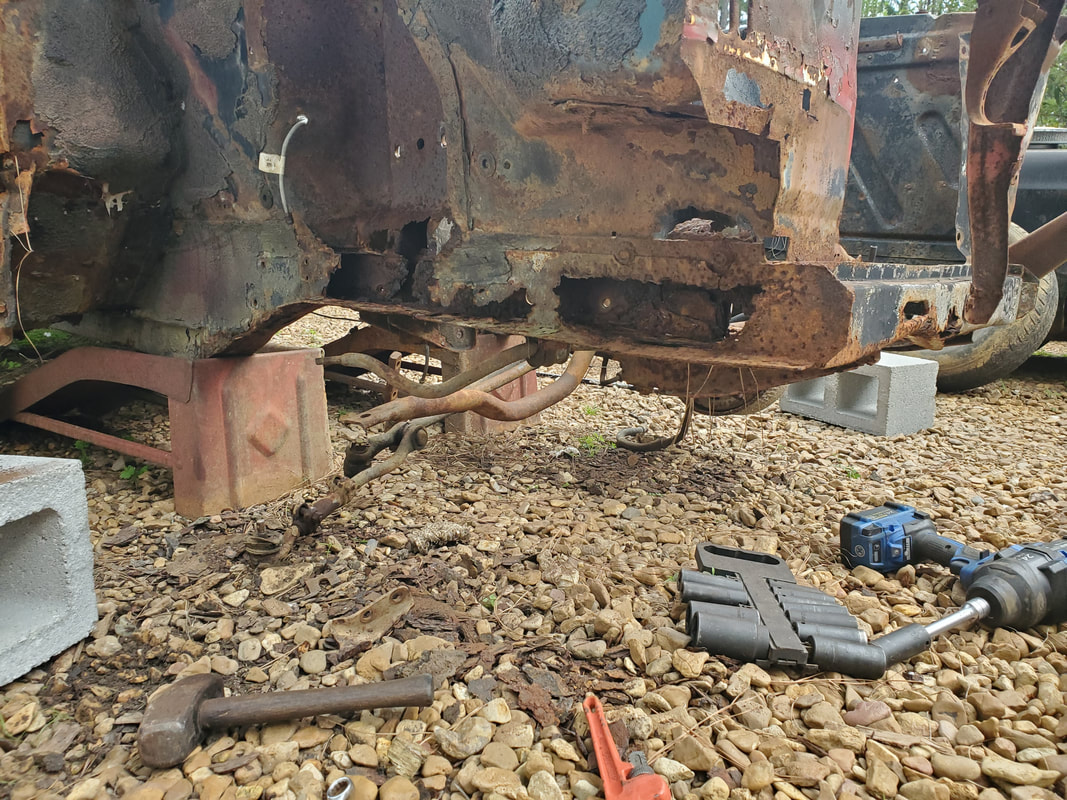
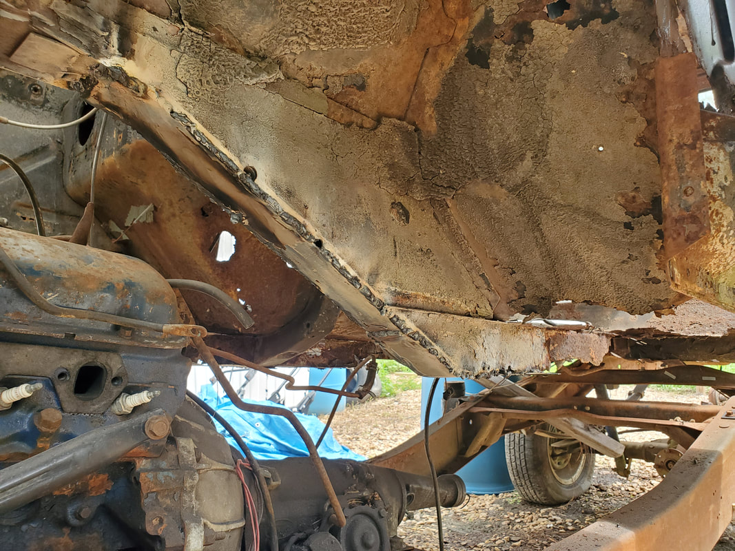
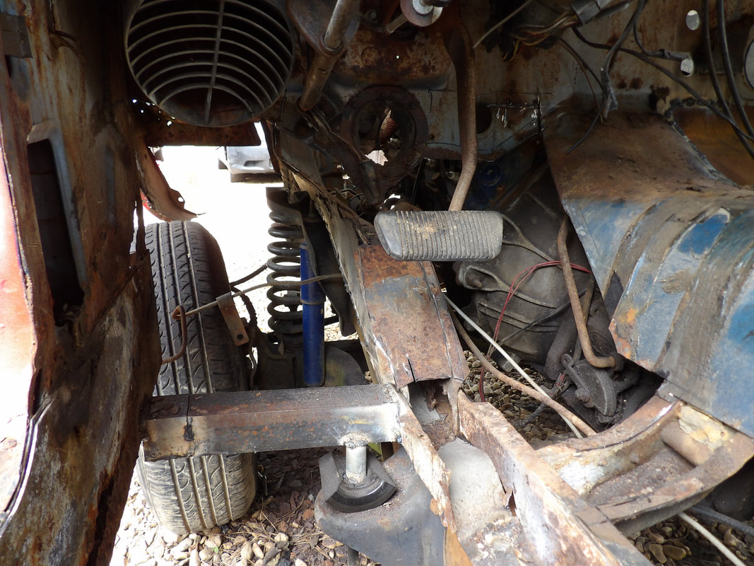
The next phase is removing all the components under the car. This includes the exhaust system, driveshaft, shifter, engine and transmission mount bolts and headers. Even though the shifter is in the cab, the linkages hook up under the car so I had to go under the car to free this up before removing the shifter. Of course I had to jack the car up and place a tarp down to get under the car since the ground was mushy and wet. After pulling the shifter I went in from the trunk area to remove the driveshaft bolts so I can pull that component free. At the same time I pulled the shocks and traction bars from under here, using my trusty cutting tools to persuade stubborn bolts and nuts that I wasn't going to wrestle with this time.
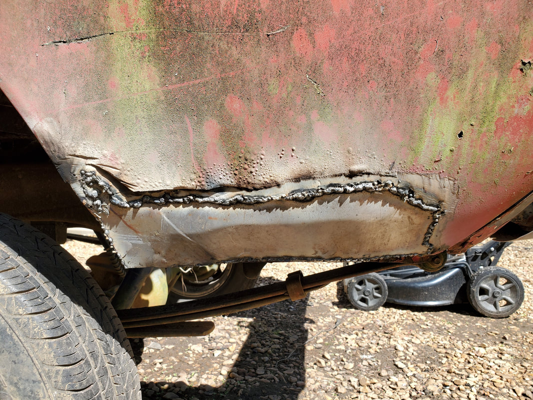
After getting the driveshaft and other crap removed I moved on to the exhaust system. Part of this involved having to cut free sections of the floor to open up areas where I needed to get in with a baby sledgehammer to hit the mufflers to help knock them free from the rest of the pipes. I removed the clamps on the exhaust system by cutting them free since I wasn't about to fight the rusty nuts on the things. After removing the bolts from the headers I was able to knock the mufflers free from the pipes to separate the sections of each side so I could get the U pipe around the rear end and out.
Rear floor sections cut out on either side behind the seat mount panels.
Exhaust pipes and other parts removed from car stacked in truck awaiting transport up to garage.
As for the headers, in order to remove those I would have to have jacked up the engine off the mounts to get the clearance to be able to slide the pieces from under the car. Since the ground was mushy I wouldn't have been able to safely do this without the risk of the jack sinking into the mud so I just went as far as removing the bolts from the cylinder heads so the headers are just free hanging. When we do remove the engine and transmission the headers will just fall free to the ground where I can then remove them.
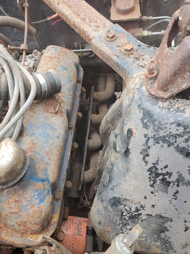
Left header resting free from engine after removing the bolts from cylinder heads.
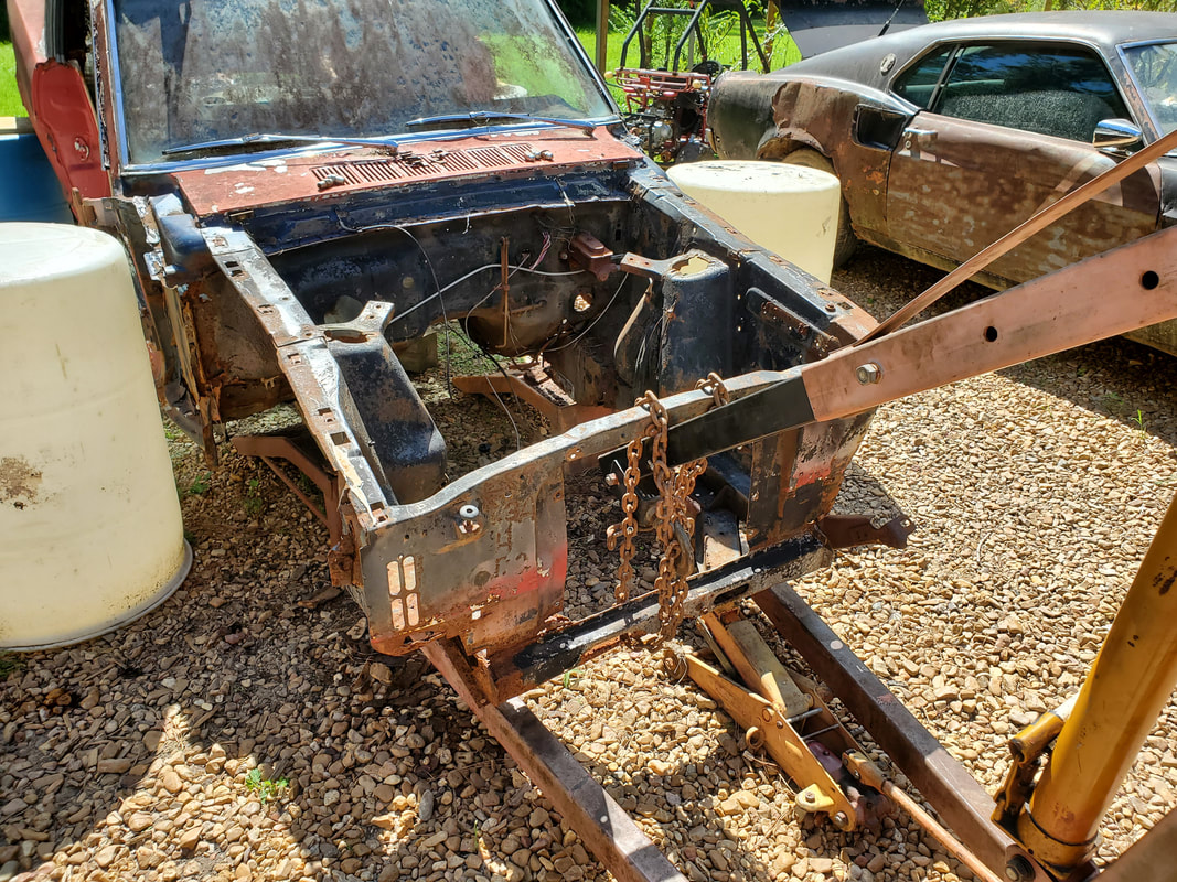
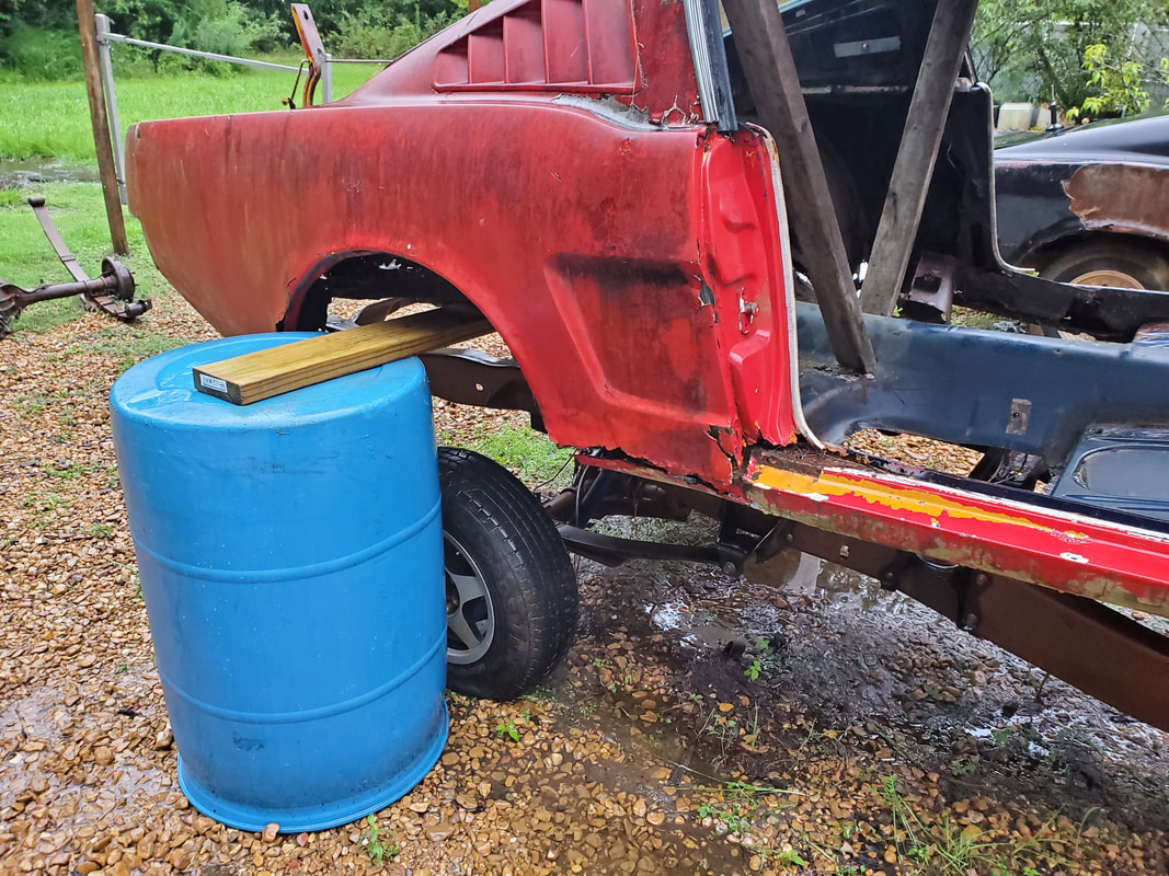
With the body completely stripped, I had to figure out a game plan for doing the truck frame swap. The plan, based on what I saw online from another body swap, was to get the Mustang's body suspended on boards posted between drums at the front and back. If I can do this, I could have the body high enough to roll the truck frame under the body for mounting. Also I could remove the old running gear, leaving just the body, in preparation for the mounting to the frame. To be able to jack the body up high enough, as also seen online, I could use the engine crane to lift the body up high enough to get the boards and drums under it. With the driveline removed along with everything else, the body should be plenty light to lift it up with the crane. Even as the body is suspended, I could remove the running gear to drop more weight in order to more easily and safely lift the body up high to get it on the boards.
Mustang relocated to spot alongside the house, after moving the 84 F150 when I extracted its powertrain. This spot is on more level ground and should be safer for our drum suspension plan.
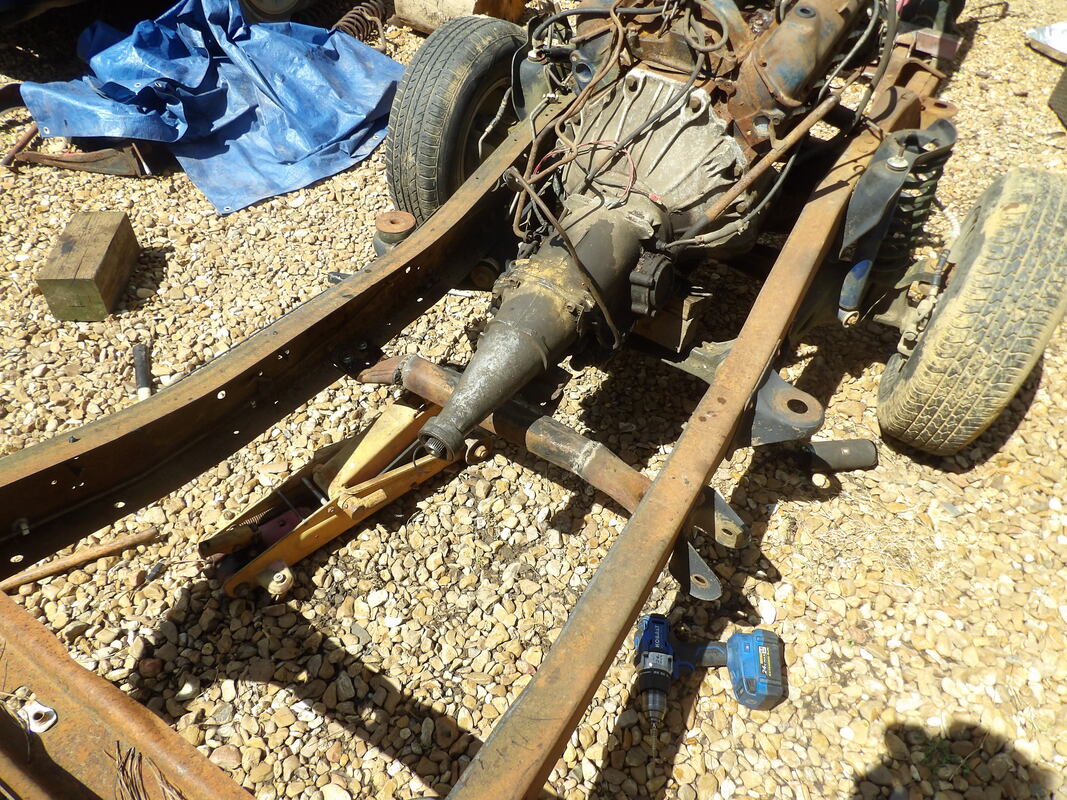
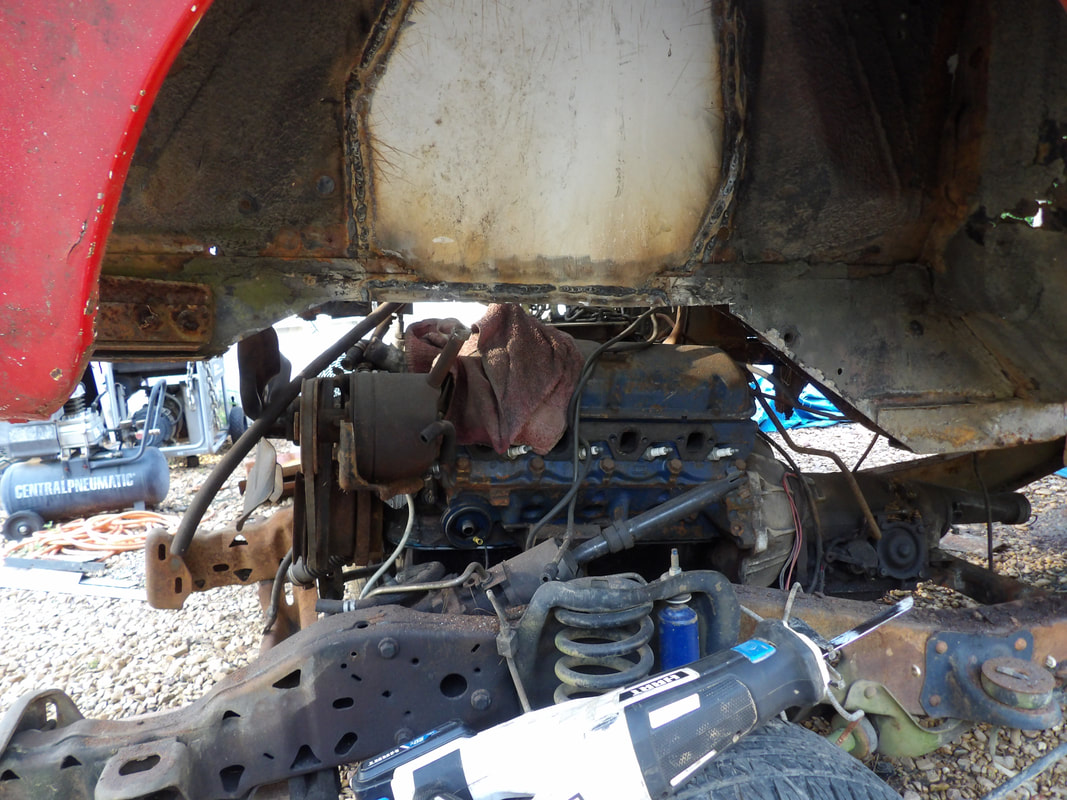
In preparation for the build, the first thing I want to do is install the engine and transmission from the car onto the Ranger frame. Before I do this I have to do a few things. When I pulled the engine from the car, I ended up using the 4bbl intake for the 302 engine that I currently have installed in the FMT. Because of me removing the intake, the lifter valley and intake ports ended up with a lot of dirt and foreign matter. This stuff would need to be removed before I can install another intake. The intake that I plan on installing is the 2bbl intake that was on the same 302 engine. Replacement 2bbl carburetors are cheaper than replacement 4bbl carbs and intakes. For the time being I'll use the 2bbl hardware, its a cheaper way to get the engine to the point of readiness and the money saved can be used for buying other parts to complete the build. The other things I have to do is swap out the front sump oil pan with a rear sump oil pan so the engine can fit in the Ranger frame. Lastly I have to change the motor mounts with Fox body motor mounts that have a mounting stud that would allow the engine to actually fit right on the Ranger frame with no further modification. Once the powerplant is installed on the Ranger frame, I can then use the engine crane to lift the car up so it can be propped on boards set between drums, giving me the clearance necessary to allow me to roll the Ranger frame under the body for mounting. Or course I'll have to strip the body of ALL hardware that can be removed. All the steering/suspension hardware will have to come off at the front, leaving just the front subframes and the rear end and leaf springs on the rear end all have to come out. Once the underside is cleared, I can start mounting the body.
The engine after vacuuming out the trash with different fittings to allow me to get into the different crevices. Before I place the intake on I will put oil over the lifters and push rods, and try to get oil on the timing chains so everything will be wet prior to ever starting the engine.
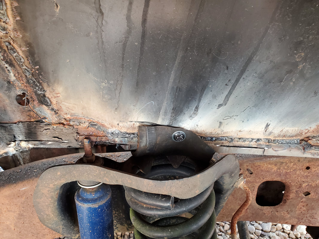
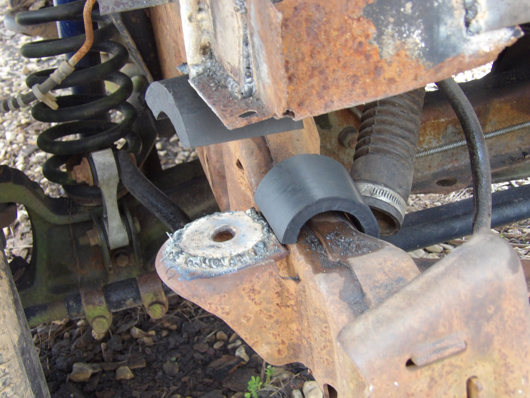
Moving back to the car body, the next move was to strip everything from the underside of the body. This would involve removing the steering and suspension hardware from the front in its entirety, leaving just the front subframe rails and nothing more. If it can be unbolted, it comes out. This started with the removal of the hardware on the right side, removing the coil spring shield and shock cap, then removing the nuts holding the bolts for the upper control arm so I could pry the arm free, which would free the coil spring. I unbolted the upper ball joint to remove the upper arm and coil spring completely, then the lower ball joint and tie rod end, along with the brake line to remove the spindle/drum brake assembly. I removed the bolts holding the sway bar and V8 bar on the right side, along with the control arm strut and lower control arm. The idler arm came out last, completing the right side. All of this was duplicated on the left side, with the addition of having to cut up the end of the power steering piston assembly stud where it was bolted to a bracket under the frame rail. Even though this may have compromised the PS piston assembly, hopefully there are rebuild parts available for these things or this is garbage, which it really was anyway. The left side mounts for the sway bar, control arm strut and V8 bar were removed, getting this hardware out. The lower control arm was the last bit of hardware to come out on the left side. In order to get the steering gearbox out, I had to remove the steering wheel, and the steering column tube, which was already removed, was able to be pulled into the cab, exposing the steering shaft, which is an integral part of the gearbox. With this, the gearbox was able to be fully removed. Next, I jacked up the rear end to get things staged for the removal of the rear hardware. Only problem is all the jack points for the rear are the exact things that are getting removed. I had to come up with a creative and not too sketchy way to support the middle/rear body. I ended up using one of the 2x8 boards that will later be used to support the body on top of a couple pairs of drums to hold it high enough to allow me to roll the frame underneath. I ended up using masonry blocks on either end of the board, with the board placed just in front of the torque boxes. I had to add a couple 2x4s that I placed on the floor just over the 2x8 board and anchored to the door sills at the roof which will help support the rigidity of the body. To further add to the rigidity, I added the floor jack with a chunk of 8x8 wood to the middle of the 2x8 to take up the warpage that was present under the weight of the body resting on it. This is all temporary as once the rear end is out, the body should be light enough that we can move it around and support it a lot better without further compromising the weakened state of the body due to the extreme rust throughout the body.
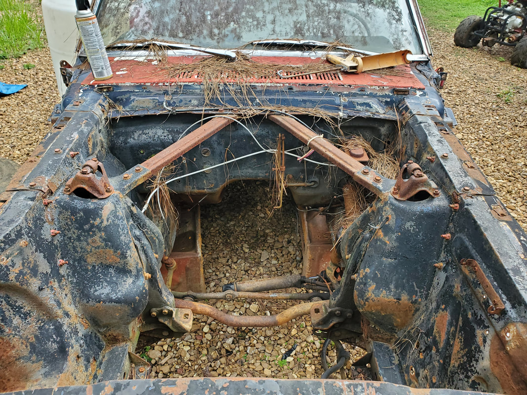
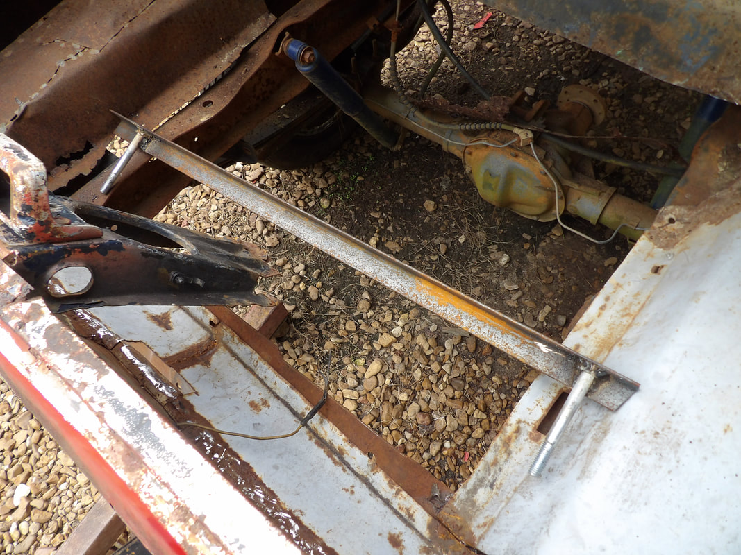
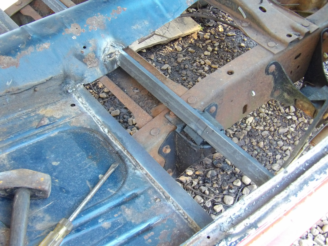
Inside shot of transmission tunnel showing the ramps and their positions under the frame rails, holding up the car body. Also note the power steering components and crossmember bar to hold shock towers apart in V8 cars.
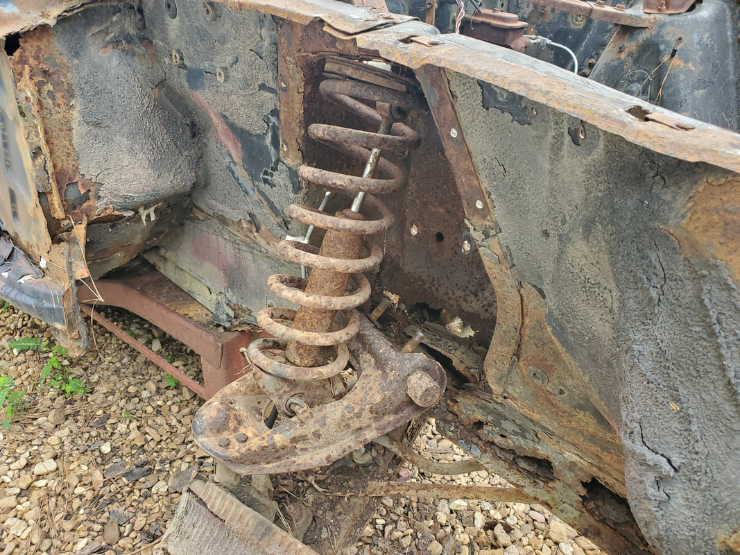
After cutting the bolts holding the shock cap in place to remove it, the coil spring and upper control arm are popped free after removing nuts holding the control arm bolts in place. A crowbar was used to work the top of the coil spring free so everything could pop out, with the shock holding the coil spring from just freely popping out.
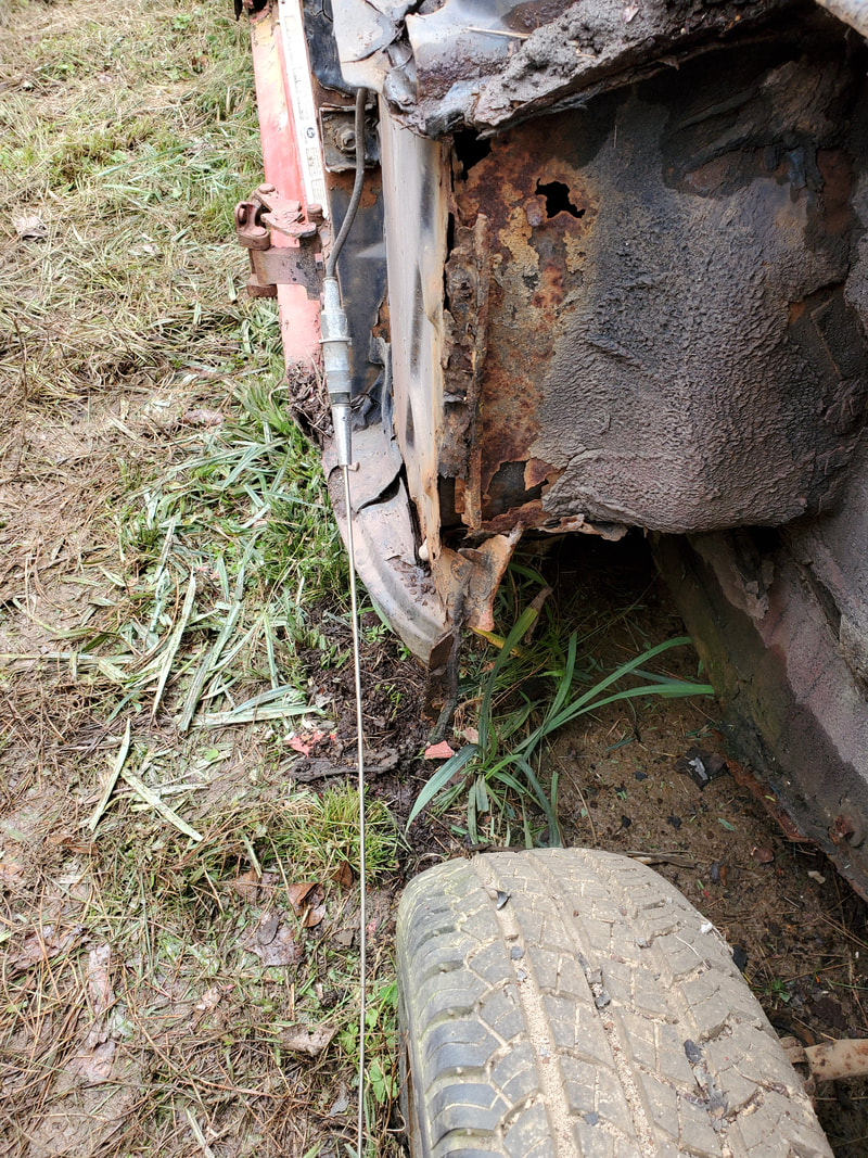
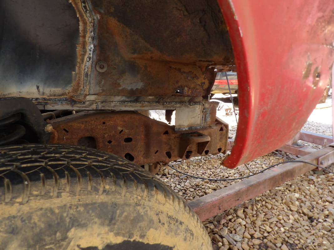
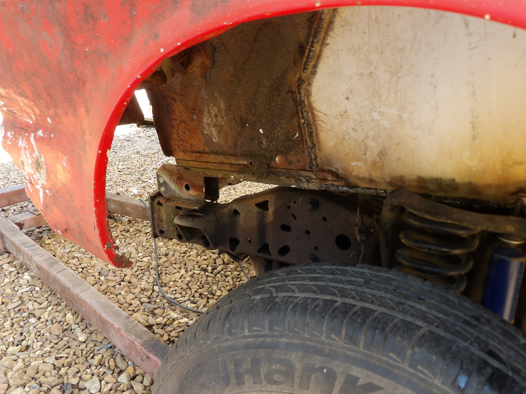
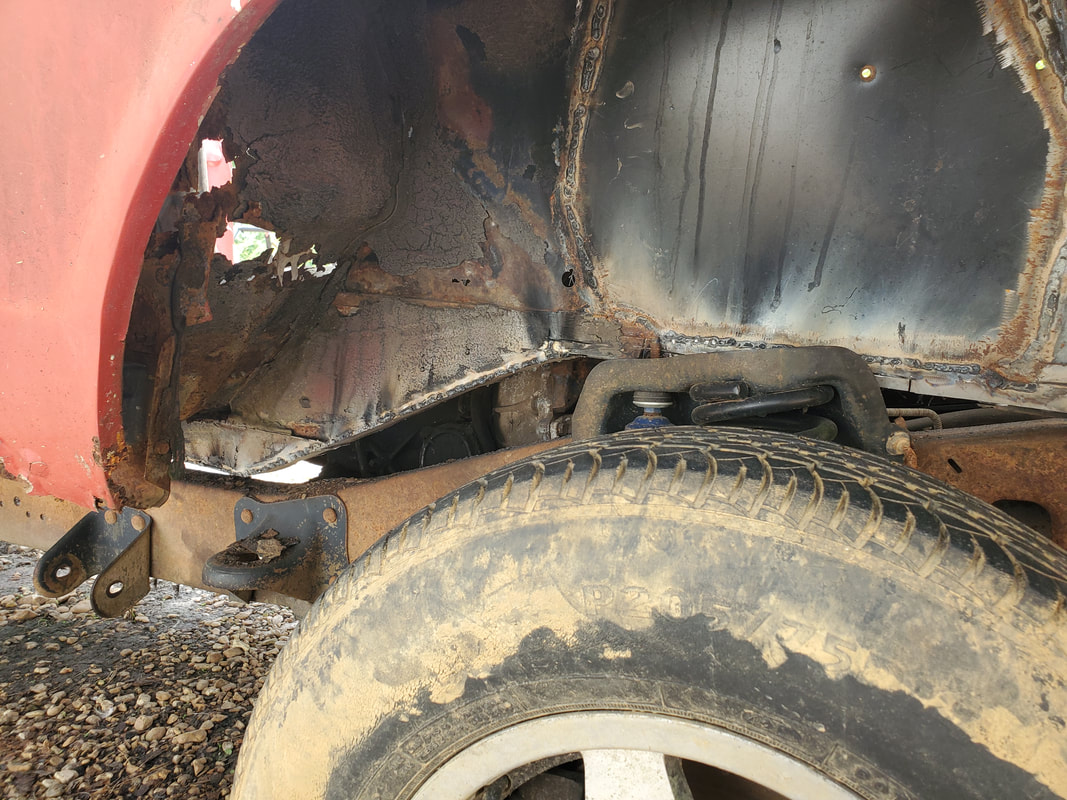
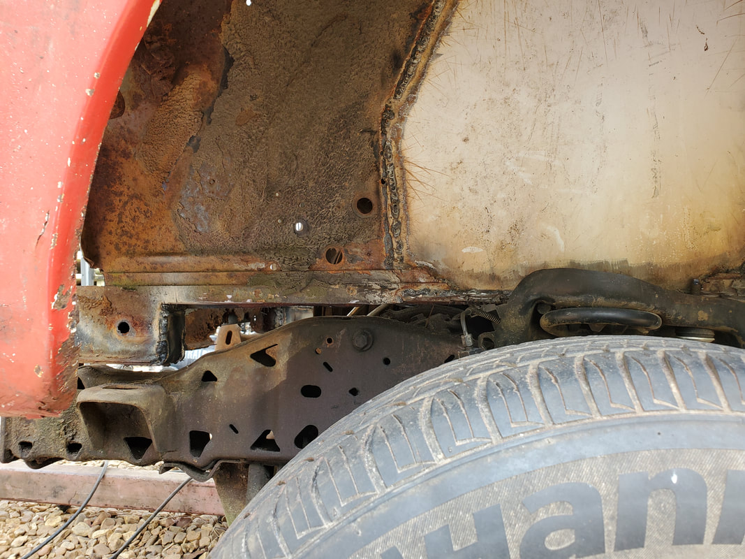
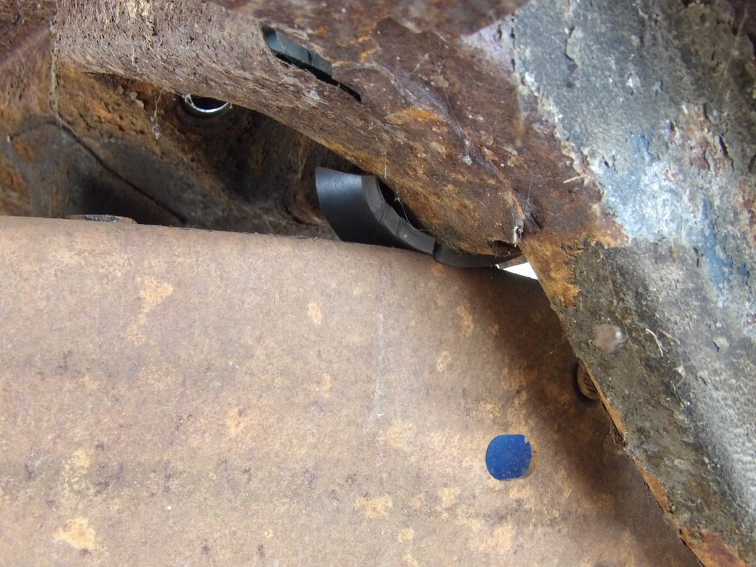
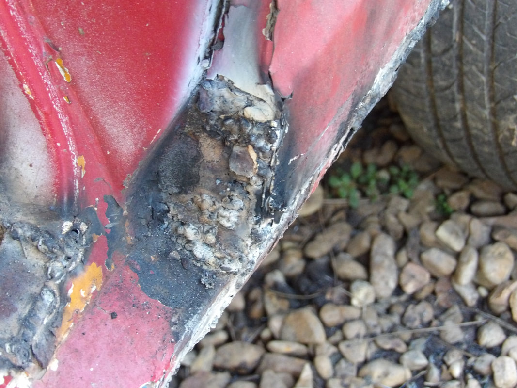
Plenty of open rust holes around the subframe under the shock tower. Even more rust damage on the rest of the frame rail, reaching to the front of the piece, showing just how bad this frame rail is.
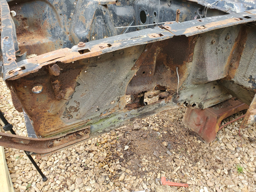
While there is some rust damage to the frame rail just under the shock tower, its nowhere near as bad as the right side.
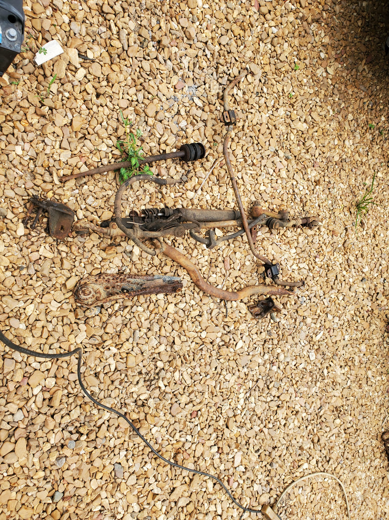
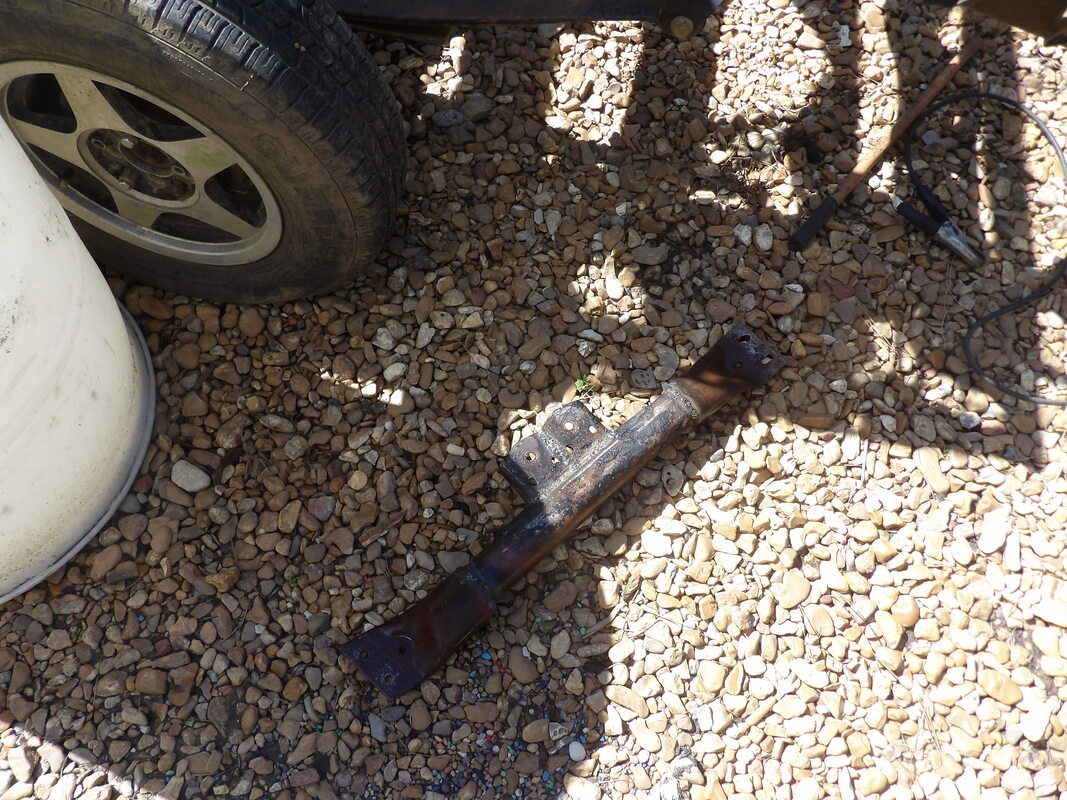
The power steering piston assembly and engine mounts along with some other hardware removed from the front underside of the car.
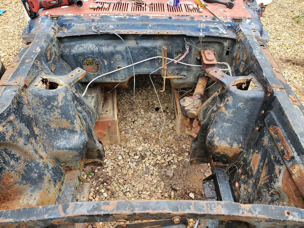
Engine bay of car void of suspension and outside steering hardware. Just the steering gearbox and shaft are left.
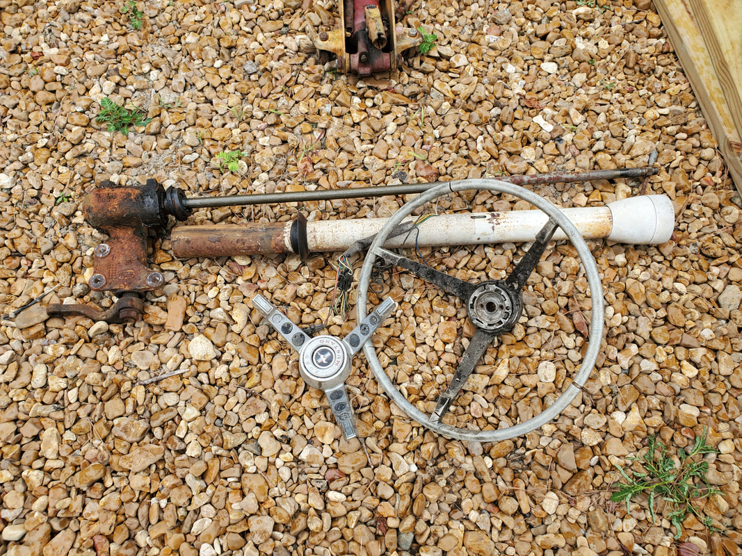
To remove the gearbox I had to remove the steering wheel from the shaft, the pull the steering column tube, which was already unbolted from the dash, from around the steering shaft, which is integrated with the gearbox. I'll probably end up cutting the steering shaft from the gearbox and welding it to a coupling that will allow me to couple the shaft to the Ranger gearbox. This will render the 65 gearbox trash, if there's no replacement shaft available to repair the unit.
Underside shot showing the 2x8 board holding up the middle of the body with the masonry blocks. First attempts by placing the blocks under the body resulted in the already compromised torque box areas trying to crumple with the rocker panels under the weight of the body when the jack was lowered.
A shot showing the masonry block holding up the 2x8 board along with the 2x4 boards placed on the floor just over the 2x8 board and propped on the upper door sills. This transfers the forces throughout the body, helping to retain rigidity of the body so it doesn't distort too much.
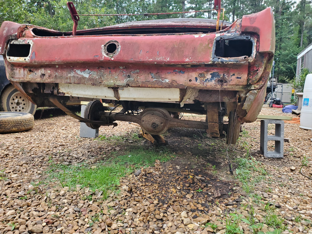
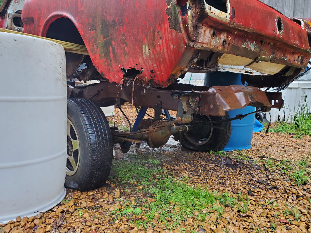
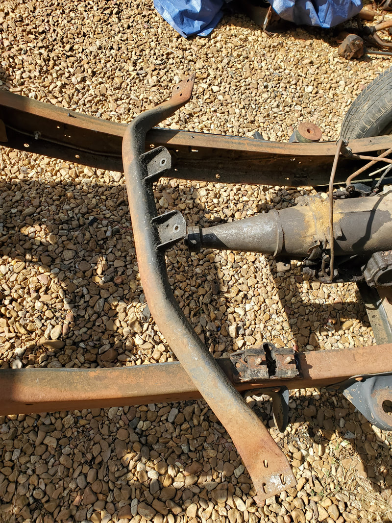
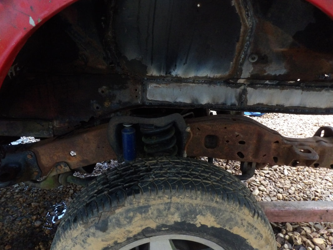
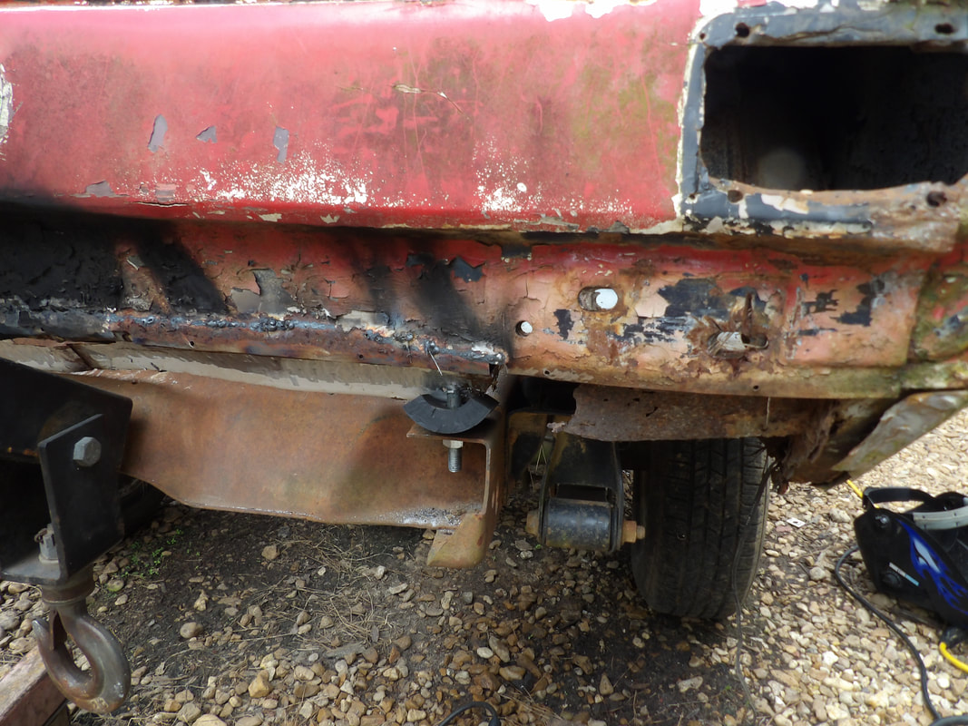
With the front end taken care of and the rear end jacked up, there's the matter of removing the rear end and leaf springs. For all intents, this would be rather easy compared to the front suspension. There's just the matter of removing the rear shackles, then cutting the parking brake lines and rear brake oil line, then cutting out or otherwise removing the bolts or mounts for the front of the leaf springs. The right side rear leaf shackle is a newer unit, replaced not too long ago when I was trying to fix the car up under normal circumstances. The left shackle is old and more than likely will need to be cut out. I was able to remove the nuts from the studs of the right shackle but had to cut out the studs from the left side. Even though the shackle plates fell free from the stud pieces, they were so rusted as to not be trustworthy for reuse. The right side came loose and is still reusable. I have the other shackle that the right side came with so the pair has been reunited for future use on another car. As stated before the parking brake and brake oil lines were cut, as none of this hardware will be reused and is rusty anyway. On the front shackles, the torque boxes were pretty rusty as it is already so I didn't expect to have to do much to get the front spring mounts freed up. Surprisingly, the left front mount was already free, as the torque box was rusted to nothing and the spring was already flopping around. As for the right side, I cut into the stud mount and a remaining part of the metal mount, not much metal, then put the hammer to the top of the mount to knock the spring free. At this point the whole rear assembly was on the ground and able to be dragged out from under the car.
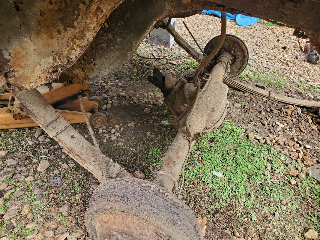
Rear end is down after cutting one spring shackle down and removing the other one intact. While I was at it, I cut the parking brake cables and the brake oil line to free those from the body. None of this will be reused.
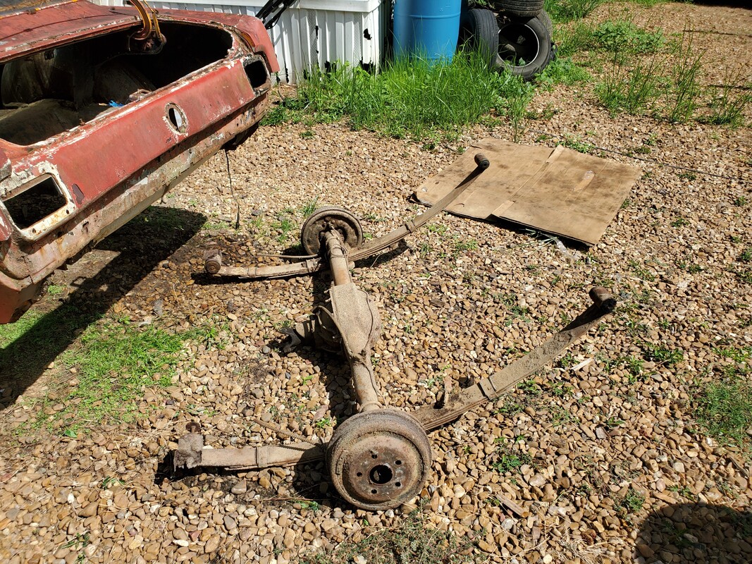
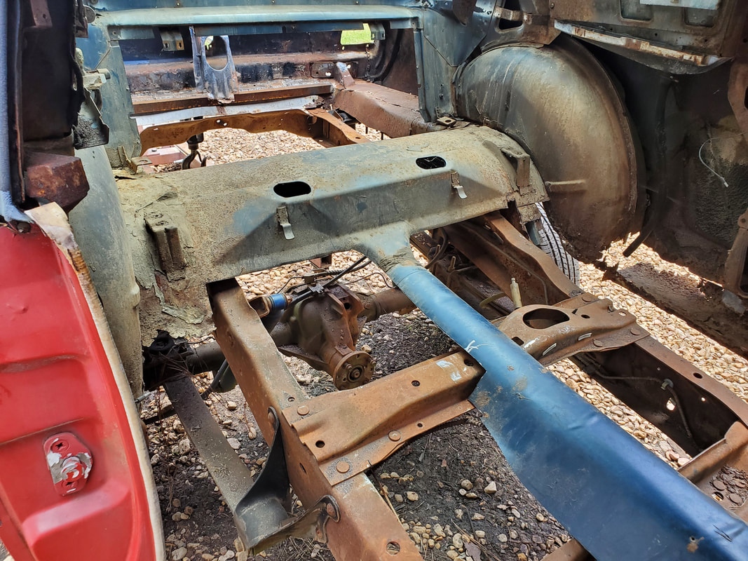
The whole rear end/spring assembly removed from under the car body. Later on after the body is done, I may attempt to cut and weld new spring/shock mounts to this rear end to allow or its mounting to the Ranger leaf springs and shocks to take advantage of the lower ratio so our C4 3 spd transmission can be used at highway speeds without the engine revving at high RPM's.
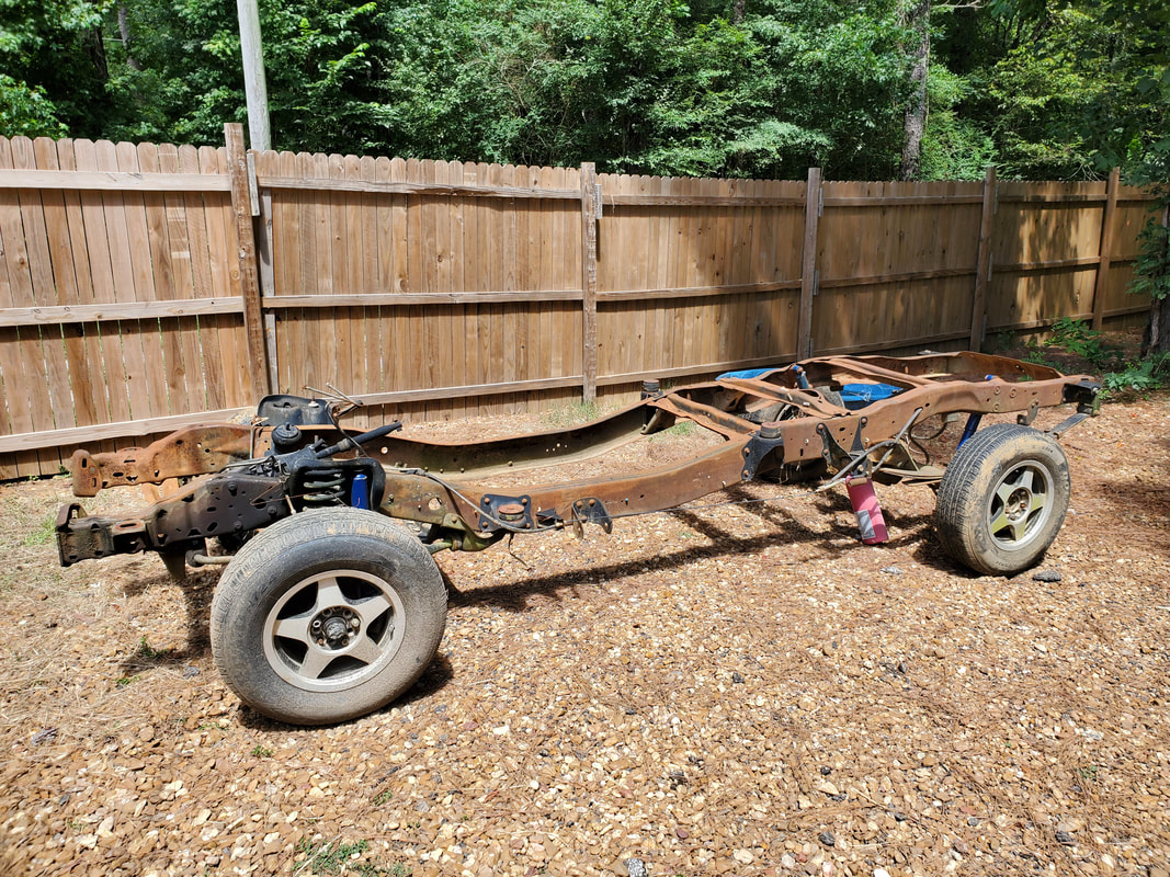
The wheels that were mounted to the 65's suspension were mounted to the Ranger frame to replace the bad tires that were present. We can now easily roll the frame around as needed.
Our next order of business is to get things set up to lift the body up high enough to be able to get the boards situated under the body and on top of the drums. This will be done using the engine crane, where the end of the boom will be placed under the body and chains will be used to help support the body to keep it from shifting as the boom is raised to lift the body. Since the body is very light as it is, the engine crane shall easily lift the back of the body off the ground plenty high to get the board underneath. The rear was done first as the front is more solidly rested on the ramps, even at the extreme angle the body will be when its lifted. After getting the rear on the board and drums, I set the crane up in the front, at first with the boom on the lower part of the radiator core support frame. When the body shifted back slightly, the boom slippped free, so I moved the boom to the upper part of the core support. With the boom at a less extreme angle, and with my holding the body with a forward force to counter the backward force of the body trying to slide back, I was able to lift the body high enough to place the board under the front subframe rails. I had to place the board on the front portion, just in front of the lower control arm mounts. This point on the frame rails sits higher than the rear third of the frame rails, which sits lower. At this placement, the body is pretty horizontal, at only about a 5 degree angle. I had to hook back up to the rear and lift it up again to get the drums and board resituated once more, as one of the drums wasn't quite plumb. With the body on the boards and drums, we can now move to the frame and the powerplant. After installing the intake and rear sump oil pan, a new set of mounts for a Fox body Mustang will allow me to drop the powerplant on the mounts of the Ranger frame. A cross member for the transmission will be fabricated from scrap metal to support the rear of the powerplant on the Ranger frame.
Chain wrapped around boom, hook and rear panel/valance to hold things sturdy while lifting. I slowly lifted the body up, watching the movements of the front, even when the ramps were tipping with the angle of the front frame rails. Once high enough, I was able to place the board under the frame rails and on top of the drums.
After trying to lift the boom at this extreme angle, The body started moving back as the boom was pushing back as well as lifting up. I moved the boom to the upper part of the core support and tried again.
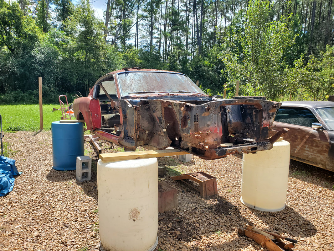
Instead of putting the boards under the rear of the front subframes where the bottom angles to a lower position, I placed the board under the front portion of the subframes. The board is just in front of the lower control arm mount. The bottom of the subframes angles up to a higher point, putting the board at a higher point than if it was placed on the rear part of the frames. This made the car almost perfectly horizontal on the drums.
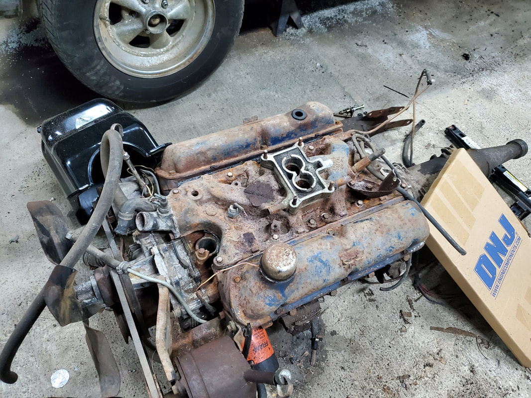
The 2bbl intake removed from the 302 that was in the 73 Mustang is now installed on the 289 V8 that'll be going back in the 65 but mounted on the truck frame.
We had a change of plan regarding the powerplant and the truck frame. Rather than bring the frame up to the garage to install the powerplant, the plan will be to load up the powerplant and crane into the S10 and bring it all down to the build site. The frame will be staged under the body for preliminary fitting and when the powerplant is set on the ground, I can install the unit in the frame before doing our final staging of the frame, with the installed powerplant, under the body. From there I'll be able to determine what old metal will need to be cut out as well as where new metal will need to be added. At the same time I'll have to repair the rotted floors in the cab area of the car and repair the sections of subframes that are kept intact in order to give the unibody the extra support it needs for mounting to the mounting brackets on the truck frame. Angle iron and flat stock iron will be added in points, sometimes creating new subframe support structures to help in supporting the body on the frame. This is necessary as the frame will be able to twist as the vehicle travels over uneven terrain.
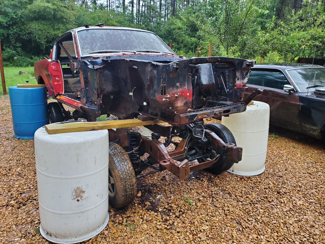
The Ranger frame staged under the body at the point it will need to be when the body is lowered in place. The rear tires had to have the air let out to lower the rear of the frame to clear the front subframes. Extra 2x4 blocks had to be placed under the frame where it rests on the front board to further raise the body for extra clearance.
Note how the rear of the truck frame is higher than the rest of the frame to the front. These angles and heights may allow for the rear subframes to rest on the top of the truck frame without having to be cut out. Also note the flat rear tires.
Shot of the rear of the frame and body showing how the truck frame seems to almost match the angles of the body's subframes. We may not have to cut out much metal to get the body mounted at a point where it's not riding too high on the truck frame.
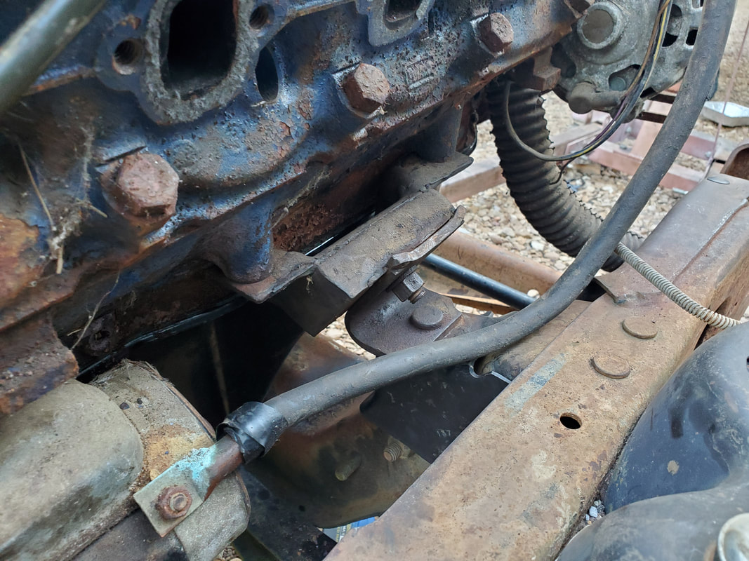
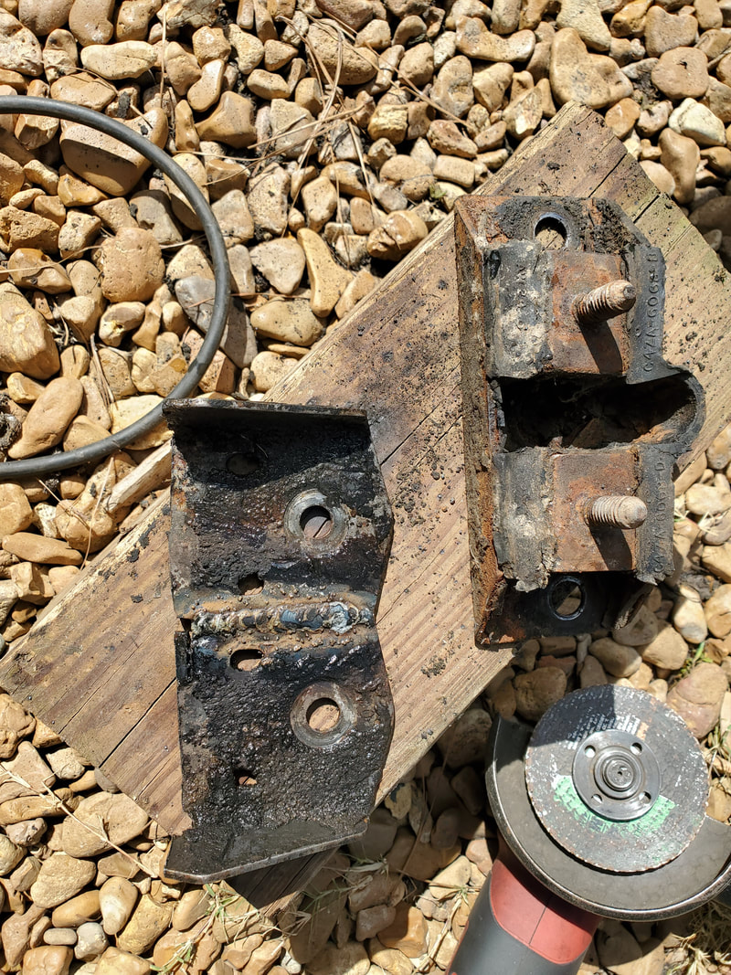
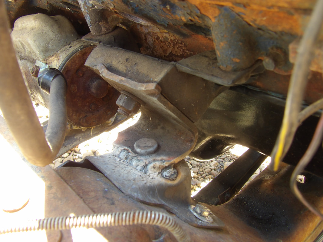
With the engine's oil pan down, I had to install a rear sump oil pump pickup screen. This involved me having to remove one of the main bearing cap bolts to secure the mounting tab of the tube. If this setup was used on the engine this was intended for, the main bearing cap bolt would've been a studded end to allow me to add a nut to the stud without removing the bolt. In our case, because the engine is a 60's vintage engine, we didn't have that option. After torquing the bolt back down, I was ready to mount the oil pan. When I removed the old oil pan, I found that I had previously installed a one piece pan gasket, which was still intact enough to reuse. I already had a new gasket but with the old gasket still good, I have a spare, which can be used on any of the SBF V8 engines. After mounting the pan, I moved the engine to the garage door to bring it and the crane down to the build site. Once down at the site, I staged the engine and crane in front of the truck frame, I had to remove the old motor mounts from the mounting brackets, reinstall the mount brackets, then did a test fit. I found out the oil filter interfered with the steering gearbox. I had to remove the filter but will have to install a remote oil filter setup to replace the missing oil filter. No biggie. After I set the engine down on the mount brackets, I found the engine had a lean to the right because the mounting brackets were not even with one another. I removed the left bracket, which was sitting higher, and cut the top off. I trimmed the body down and welded the top back on. This put the mount bracket at a lower level than before, helping to level off the engine more. From there, I had the "fun" time of trying to get everything to secured together. I tried to torque down the nuts on the motor mount studs from the 289 mounts to the Ranger mount brackets and that was fruitless. None of this stuff fit flush to one another during the test fit so when everything was fitted down flush, nothing went together right. I had to loosen the studs on the 289 mounts and set everything back down with the odd angles that everything was at during the test fit. I figured out a way to fix this little dilemma. After setting the engine down on the loose fitting mounts, I'll weld up the 289 mount brackets to the Ranger mount brackets, making everything be one piece. Replacing the mounts would involve removing the two bolts from the block and the nut and stud that hold the actual mount to the bracket. I could've just made the mounts be permanent mounts but I could still use actual mounts in this new arrangement. The next order of business will be to make a transmission crossmember.
Rear sump oil pickup tube mounted in place. Note the main cap bolt holding the tube in place. The oil pump remains the same throughout the years from the 60s through the 90s when this oil pickup was used.
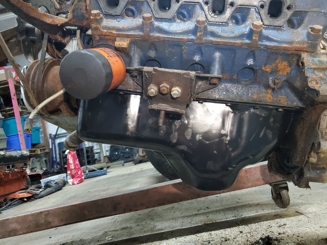
Side shot of the rear sump oil pan bolted in place. The one piece gasket can take extra torque on the bolts and not damage the gasket, compared to the cork four piece gaskets normally used on this engine. Note the extra bolts holding the motor mount to the mount bracket as a way to repair the broken mount. This was done a long time ago, making this a permanent mount.
Prior to test fitting I had to remove the old Ranger engine mounts. This involved removing the mount brackets, held with two large nuts to a double stud bracket and a single bolt/nut. I cut out the single bolt on each bracket. During the initial test fit the oil filter hit the steering gearbox. It will have to be removed and replaced with a remote oil filter assembly.
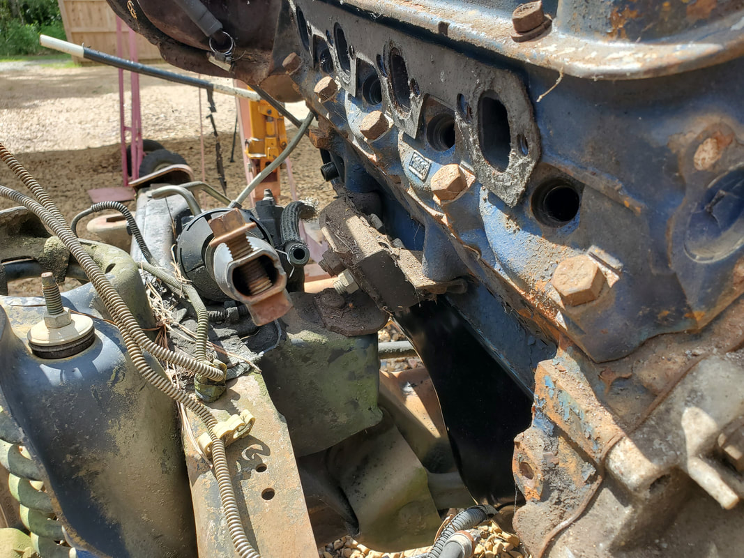
Setting the engine down revealed that the mount brackets on the Ranger frame are not even.
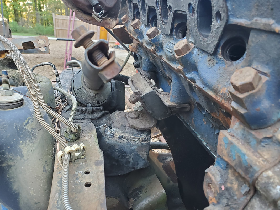
The engine resting on the "new" mount bracket. Unable to fully tighten the mount bracket stud, I had to leave it loose to secure the whole works together. I'll end up welding the 289's mount bracket and the Ranger mount brackets together in this position in order to make a single mount bracket. The two bolts holding the mount to the block and the single stud on the bottom of the mount would be how the real engine mount is removed.
The right side mount secured to the Ranger mount bracket, loosely like the let side. Same as the left side, I'll have to weld this together to make a single mounting bracket.
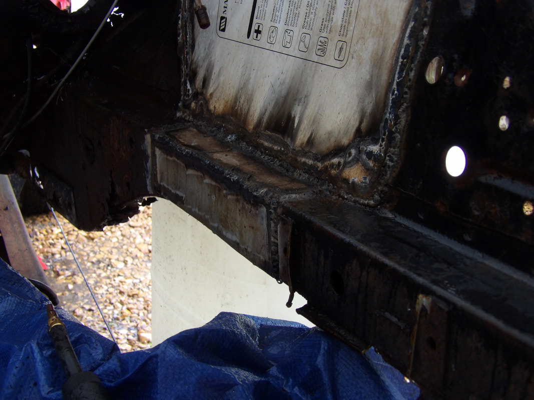
Engine/transmission mounted on the Ranger frame. I will have to weld the mount brackets and make a transmission crossmember to complete the installation.
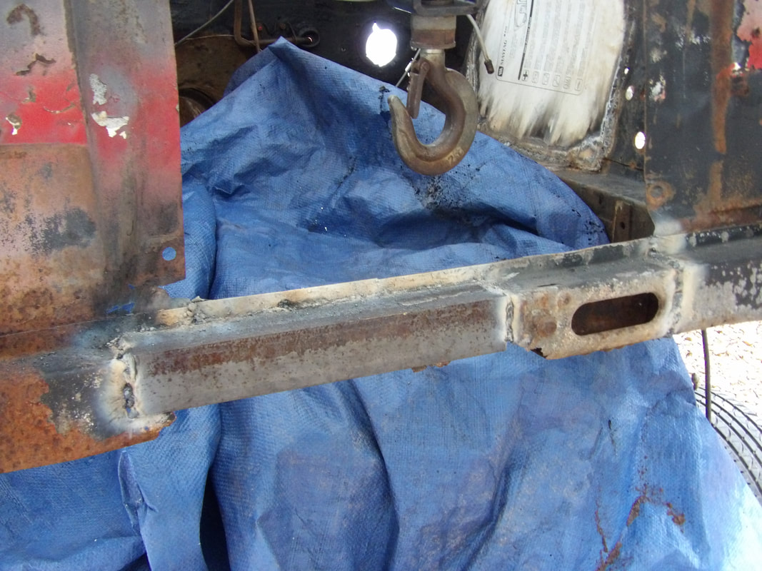
Our next task is the transmission crossmember. At first, I was going to make one from scratch with angle iron but after looking at my scrap parts pile, I found the crossmember from the minivan we gutted for the chicken coop project. This crossmember is too big to be used on the narrow Ranger frame, but with the tools I have available, I can cut and trim and weld this piece together to make a crossmember made to fit. The first thing was taking the two mount tabs, one of which was for the transmission, and cutting these off the crossmember bar, trimming them then welding them together. I used the C4 mount as a gauge to determine how much material to cut off before welding the two pieces together. Once the pieces were together, I then took the crossmember bar and cut the piece into thirds. I took the center piece, which was a straight tube, and welded the mount base to the tube. I then mounted the center piece to the mount which was reattached to the C4 transmission. I was able to trim the two end pieces to fit, with the mounting tabs laid on the frame rails. Even though the ends of the tubes were not even, I butted the ends together and welded everything up, filling the extra space with extra slag to ensure a good solid weld up. With the new crossmember made, I had to drill the holes on the truck frame to secure the crossmember. I started by drilling two pilot holes at a slight angle from the top, while the crossmember remained bolted to the transmission and setting on top of the bottom lip of the frame rails. Once the pilot holes were done, I used a step bit to drill holes from the bottom to ensure the holes were lined up with the holes on the crossmember. With those holes done, I then moved the crossmember mounting points to under the frame rail, bolting the left side in place with the new holes, using grade 8 bolts. I then I was able to accurately drill two pilot holes from the bottom on the right side into the frame rails. The step bit finished off the holes. I put the crossmember back on top of the bottom lip of the frame rail and secured to the transmission mount. I secured the two ends of the crossmember with grade 8 bolts, holding the unit in place on the frame and under the transmission. I removed the boards from under the transmission, putting the whole power plant exclusively on mounts. The last order of business was welding up the motor mount brackets. The Ranger mount brackets and 289 mount brackets couldn't be bolted together securely due to the uneven nature of the whole setup. With the nut that held the stud on the 289 bracket to the Ranger bracket being loose on each side, the only option was to weld the two brackets together to make one greater bracket. To remove the actual rubber mounts, I would remove the two bolts holding the mounts to the block and the nut holding the stud on the bottom of the mount to the bracket. I could also make the motor mounts a permanent but more than likely I'll still try to use regular mounts, so long as I don't have any issues with replacement after the fact.
The minivan transmission crossmember I dug out to be used for our made to fit crossmember.
Both tabs welded together after fitting on the C4 mount.
The finished crossmember, welded together. After welding the top 2/3 of the ends together, I removed the crossmember and flipped it over to get the remaining third. I had to weld in extra slag filler to fill in the gaps left between the ends due to the uneven metal.
The made to fit crossmember mounted in place on the frame and under the transmission.
Since the nut holding the stud on the 289 mount bracket couldn't be tightened against the Ranger mount bracket, I welded the two brackets together at the angle they sit with the engine secured in place. The rubber mount can still be removed with the removal of the two bolts at the top and the nut holding the stud into the 289 bracket.
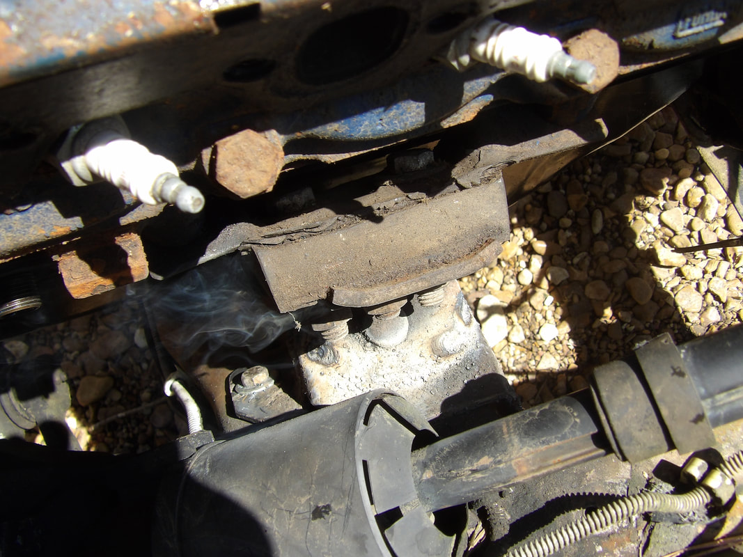
The still smoking mount brackets, welded together o the driver's side. This rubber mount was bolted together to make a permanent mount, which could be done to the right side as well, negating the need to ever have to replace mounts. The cushion of rubber and the bolts not being torqued down hard still give the mount a little cushioning effect.
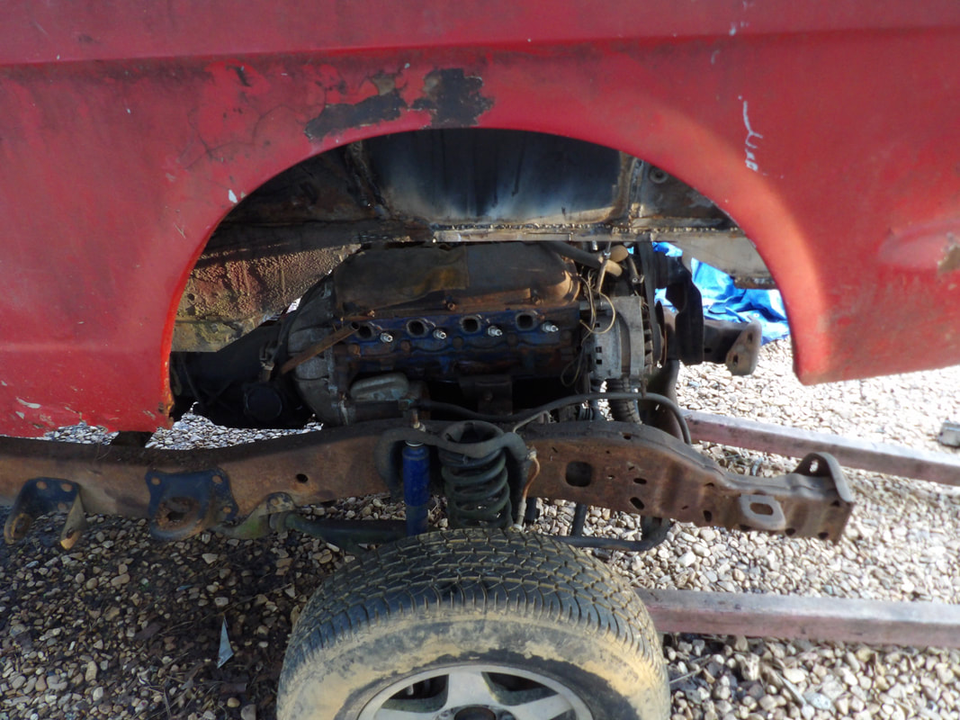
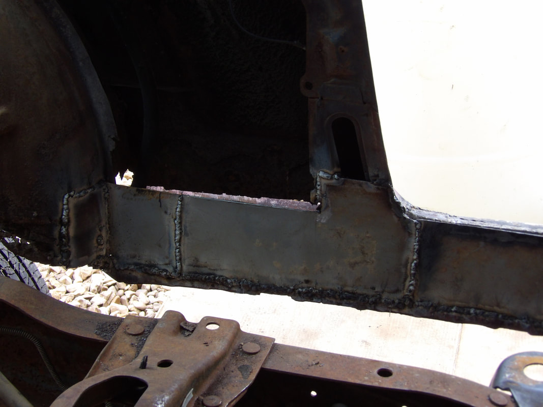
With the powerplant installed in the frame, I can now start the next phase of the project, which is the fitting of the body. This will involve having to cut out metal from different points in the engine bay, subframes and possibly the floors to facilitate fitment on the frame. The first area I targeted is the control arm strut mounts on the front corners of the engine bay. Once I got through whittling away at that metal, I was able to free all of the rusty and unnecessary metal. With that metal gone I cut the piece of metal on the bottom of the core support. This allowed me to roll the frame under the body, as the engine had to be able to clear the core support area. Once underneath the body, the next move was to start hacking the shock towers. In order to get the frame under the body, I had to move the front board. In order to do this I had to find alternate mounting points for the front of the body. I put the engine crane back in position, having to use a board on the bottom of the core support to keep the front rom buckling, then lifted the body high enough to place the drums under a structural support point that was behind where the fender and door would meet. With the body supported once again, I started cutting the shock tower. I cut everything away, down to the frame rail, leaving a large hole. The other side doesn't have much frame rail left but is cut the same way. I welded in some rigid sheet metal in the holes to fill them in, as well as some iron around the frame rail and the top of the side panels, to restore some of the rigidity.
Left side frame rail with the control arm strut mount/brace cut free. Also note the bottom of the core support that's also cut free.
Right side frame rail with cut out strut brace. This side was rustier than the left side so it didn't take a lot of effort to cut this out.
Opening on the right side after cutting out the shock tower. Note the level of rot on the subframe.
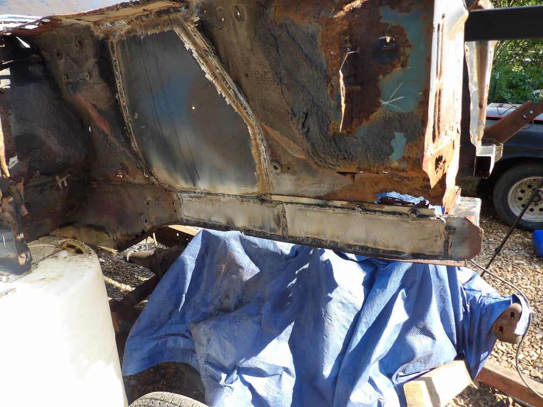
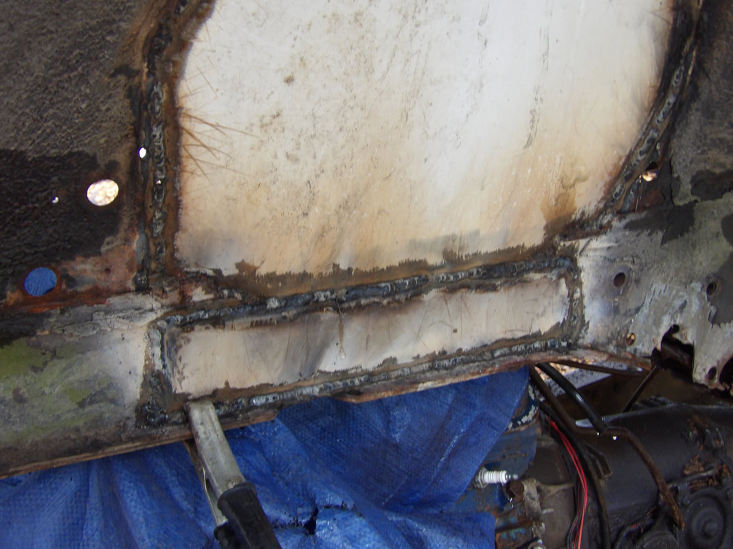
With the holes prepped and the patch panels made and ready, I moved on to weld the pieces in. I started off with spot welds all around, taking time to use a hammer to tap the metal and hold it against the side walls so the spot welds hold a nice tight seam. Once the spot welds were done, i then welded complete beads all around the edges of the panel. I couldn't weld anything on the bottoms of the panels due to the missing metal of the subframes. Once the outside welds were done, I went ahead and welded the inside edges of the patch panels completely. With the panels completely welded in, I was able to move on to the small patches that needed to go over the lip of the side walls just over the shock tower patches.
With the shock tower patches welded in I moved on to the subframes themselves. I dug out some scrap rigid sheet metal for use in this application, and after cutting the necessary patches for both sides, I welded everything in on the two subframes. On the left side I even welded in a patch but only halfway, since I don't know how much of the bottom of the subframe I'll have to cut out in order to allow the bottom of the subframes to mate to the Ranger frame. I also welded in the core support piece I cut out earlier, and added a piece of angle iron to reinforce one of the joints, since the piece was already pretty rusted as it is. Once all this was done, i bolted the fenders back on, along the top, so I can begin the fitting process. I used the engine crane to jack the front of the body up and remove the drums from under the body. Once I lowered the body to the frame I ran into my first big problem. First, the spacing between the subframes is not the same as the spacing of the Ranger frame rails. This caused the bottom of the subframes to hit the tops of the Ranger frame shock towers. This means now that I'll have to cut out some of the metal from the bottom portions of the subframes, even some of the metal I welded in. At the current position, there is a lot of spacing between the top of the engine and the top of the engine bay. There is also a lot of space between the fender arches and the tops of the tires. What this means is I'm going to have to remove a lot of metal from the subframes to allow me to get the front of the body low enough to mate to the Ranger frame and close the spacing gap between the fenders and tires.
Shock tower delete patches welded in place along with the front subframe patches welded in place on the right side. This side was the worst off and required the most patch metal.
The inside of the right subframe with the smaller patches welded in place along with the inner weld bead on the shock tower patch.
Left shock tower patch along with the subframe rail patch, which was smaller compared to the right side.
Inside of shock tower patch and subframe rail patch. Even the inside of the left subframe required a small piece of metal compared to the right.
Half welded piece of metal under the left subframe. I don't know how much metal will have to be cut from the lower portion of the subframe so this metal was left unwelded so it can be finished off once the trimming was done on the subframe.
Angle iron welded in place to reinforce the core support piece. Even the angle iron couldn't be welded too good due to the rusty metal on the right side. The rest of the angle iron is welded in solidly. This point isn't going to be a load bearing section, it's just for maintaining the proper spacing of the two sides so the front body pieces will fit back together properly.
Front of the body supported on the engine crane and the drums removed from under the body.
First problem encountered with the bottom of the subframe hitting the shock tower. Metal will have to be cut out to help fit the body better to the Ranger frame, including metal I just welded in.
With the excessive ride height of the body after lowering the body down where the subframe is sitting over the Ranger frame, I realized I will have to cut out some of the subframe metal, even the metal I just finished welding in. I have to start off with the area over the Ranger frame shock towers due to the idea that the subframe is resting on the shock towers. With the angles of the Ranger frame, I'll most likely have to cut out more than just the area over the shock towers in the end. I thought about it and changed my mind about the willingness to cut past the top of the subframes since this would completely destroy the structural integrity of the front body. Adding a tubular chassis would possibly lead me down a rabbit hole that could have me cutting more and more metal from the old unibody until I'm building a full body tubular chassis and essentially putting a skin over a dune buggy body. Once the body is down as far as it can go, I can start fabricating body mount brackets to secure the front of the body. I did think about the idea that lowering the rear of the body could have the rear portion of the subframes making contact with the Ranger frame and act as a fulcrum, causing the front of the body to teeter back up, possibly compromising the front mounts and maybe even distorting body as a whole. This will facilitate cutting more metal from the rear subframes to prevent this from happening.
The left side with all the cuts made to open up the subframe around the shock tower and the part of the Ranger frame just forward of the shock tower.
Finishing up the cuts on the right side subframe to clear the shock tower and Ranger frame.
The next series of cuts made to the subframes. I took a little more metal out, but left the front few inches in order to have somewhere to weld on a body mount bracket later. Also note the contact point just forward of the shock tower where the top of the subframe touches the Ranger frame.
Left side after cutting out more metal. Note how the subframe touches the Ranger frame in this area and clears the shock tower as well.
The body rides a little lower now, as noted by the way the front of the subframes rest on top of the front of the Ranger frame. I can now start boxing in the subframes after doing all the cutting so I can close that all in before welding up body mount brackets.
I made one final modification to the front subframes before I considered the metalwork done in this area. I trimmed more metal from the rear points on both subframes to take away that concern about the body making contact when we lower the rear of the body onto the frame. I also welded the sheet metal strips over the open subframe boxes to close these areas in as well. On the left subframe, the inside is rusted out enough that it would require more metal to fully close in the subframe. Since these areas are no longer going to be load bearing, there's really no need to try and fully close these frame boxes in. The sheet metal strips welded under the subframes are more for providing a cushioning between the body and the Ranger frame when the body is down than it is to strengthen the subframes. I closed in the front most points of the front subframes as well. This only took a few small pieces of sheet metal to complete. After lowering the body down to the frame and shifting if to set it between the studs on the shocks, I found the spacing between the rear of the subframes and the Ranger frame was better. The fronts of both subframes were closer to the Ranger frame with one side almost on the Ranger frame and the other side slightly higher but very close. The tops of the subframes under the old shock towers still rested on the tops of the Ranger shock towers. At this point I'm ready to make the body mount brackets, but I've also thought about the idea of using old hose as cushioning between the subframe rails and the Ranger frame rails, even after I do secure the body mounts.
Left rear section of subframe after trimming more metal and welding the sheet metal strip in place.
Right rear subframe after trimming and welding of sheet metal strip in place. Note the inside of the left subframe and how its heavily rusted out.
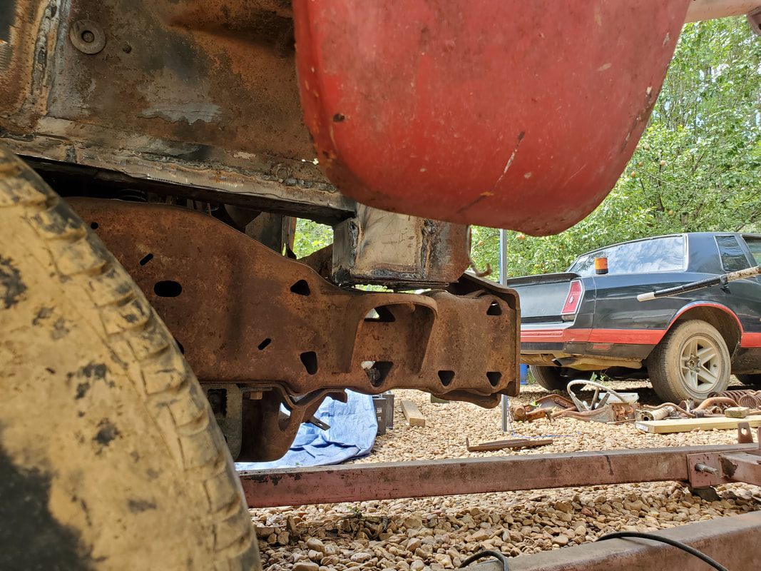
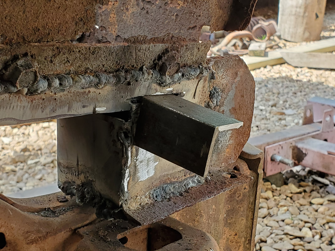
Right front section of subframe after patching open point with a small piece of sheet metal. This area is where the body mount bracket will be welded at. I will have to make a bracket that attaches on the inside and outside of the subframe, through the side panels and around the frame rail to ensure its strength in holding the body to the Ranger frame mount.
Right side subframe at the front. It required more sheet metal to fully patch the section of frame box. Again, this is why the mounting bracket will need to be a lot more than just a 90 degree piece of angle iron holding a bolt. It will be supporting the full weight of the front of the Mustang unibody on both front corners.
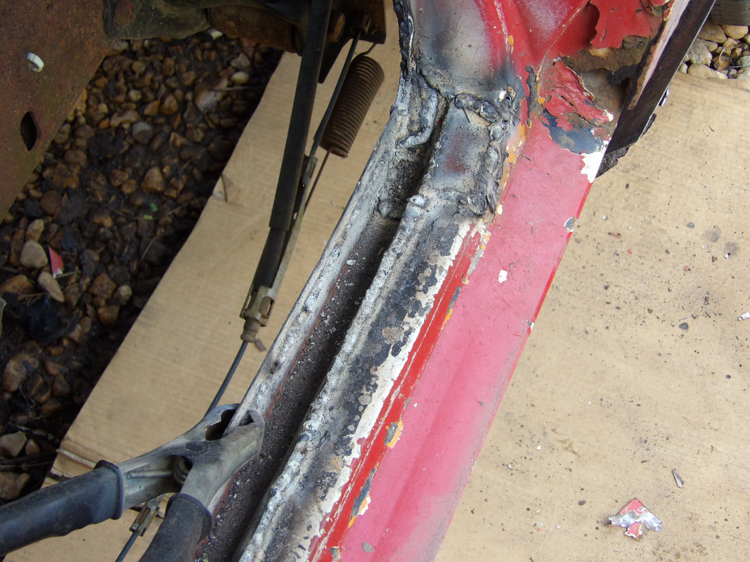
The Mustang body after being lowered back onto the Ranger frame. Note how the fronts of the subframes sit on the top of the truck frame.
The rear of the right subframe has a good amount of spacing between the angle point and the top of the Ranger frame. The tops of the subframes still sit on the tops of the Ranger frame shock towers. When the body is fully mounted and cushioning added, the body will be raised up to take it off the shock towers.
The front section of the right subframe as it sits over the Ranger frame. It barely touches the top of the truck frame here.
Left side rear section of subframe at the angle point, also has plenty of spacing between it and the truck frame.
Left front section of frame rail as it sits over the truck frame. This side sits a little higher over the top of the frame, this could be due to a minor distortion in the Ranger frame or in the Mustang unibody subframes. Its nothing that will hinder the mounting, it means that I will have to take these variations into account when I fabricate the mounting brackets and mount the body.
Now is the time that I decided to address another small issue. This is with the idea of cushioning the body against the frame when everything is mated completely. We had the problem of the body making contact with the tops of the Ranger frame shock towers. Even after I do get the front of the body secured to the frame, this contact point can be a problem as far as lessening the noise inside cab. The idea that I had regarding this problem is to add some old rubber hose between the body at the point under the subframe and the shock tower. I took some old radiator hose and cut two 5 inch sections of hose, then slit the pieces lengthwise. I spread the hose piece around the underside of the subframe top and attached it with a single self tapping screw to the shock tower patch. With that contact point covered, I moved on to the front of the subframes where I plan on making some kind of mounting apparatus. The plan I came up with for that involved adding a piece of angle iron cut with a tab, then cut a groove just above the subframe, above the Ranger body mount bracket. I sild each angle iron piece through the grooves. The plan here will be to weld these pieces against the subframe at every angle where the pieces make contact, then weld a long 1/2" bolt against the subframe and angle iron where the bolt will extend down into the Ranger body mount bracket. Some thick rubber will help in the cushioning while a large washer or some similar metal with a small hole will cover the large hole on the body mount. This will allow the 1/2" bolts to be stationary while the rubber will help in cushioning. I might make changes based on whether I get any new hardware that may change that plan.
The body is lowered onto the frame with the hose piece making contact with the shock tower, achieving the intended goal with this process.
Angle iron piece with section cut out to provide a tab that is inserted through the groove cut above the right subframe. Angle iron will be welded along the outer surface of the subframe and a bolt will be welded vertically between the angle iron and subframe surface. Angle iron will provide extra reinforcement to the bolt as it supports and secureds the body to the frame.
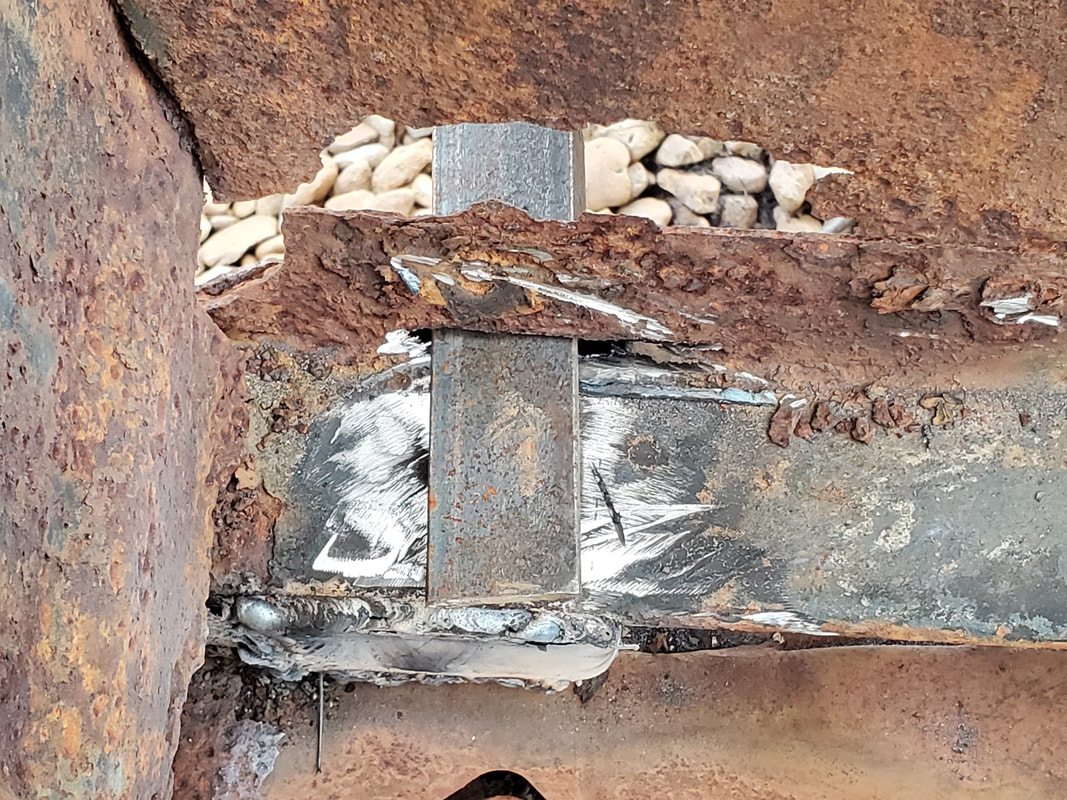
The tab on the angle iron piece as it extends through the groove and onto the top of the right subframe box. Tab will be welded along these edges as well for extra reinforcement.
With the angle iron in place, the next order of business was to start welding in the 1/2" bolts. On the right side the bolt went in with the angle iron, leaving enough stud to reach down into the body mount on the Ranger frame. I welded in enough slag to ensure everything was held in good. On the left side the angle iron went in good but I had concerns with the bolt as it appeared the bolt might not reach down enough through the body mount. When I lowered the body down, not only was I right about the bolt but the bolt was actually off center from the hole on the body mount. I ended up cutting the protruding stud off and welding a 2nd bolt in place forward and lower from the old bolt. This worked out fine, so the next move was to fit a couple large washers over the holes on the body mount brackets. Once that was done I lowered the body again and with the bolt studs in the washers, welded the washers in place on the body mounts. This way, the body won't be able to shift sideways. Next was the cushioning. This would be achieved with some thick rubber pieces I cut from some scrap. I drilled a hole through two pieces then pressed them over the studs of the bolts. I also laid a piece of rubber next to the body mount, on top of the Ranger frame on each side. When I laid the body back down, the stud went through the washer and the cushion did its job of being sandwiched between the body mount and the Mustang body/bolt. The other piece of rubber was also sandwiched between the Mustang body subframe and the Ranger frame. Nuts and washers secured everything nicely. Once that was done, I moved the crane to the back and jacked the body up, removing the drums and board. With that done, I laid the body back down, finding out that there was metal in the back seat/shock tower area of the Mustang body that hit the tops of the shocks on the Ranger frame. This had the body riding much higher than it needs to be so I'll have to hack out metal in the rear of the body to help lower the body down further onto the frame. I need the rear subframes to be as close to the Ranger frame rails as possible while trying to achieve a level plane on the body.
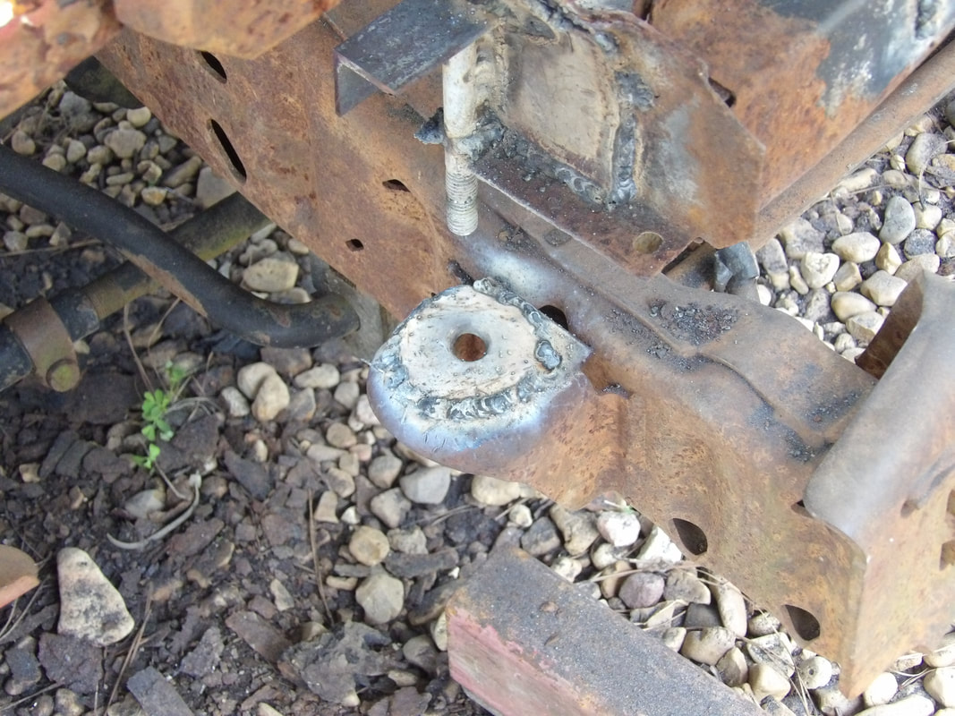
Large washer welded on right body mount.
Rubber cushion inserted on bolt stud with extra rubber on frame next to body mount.
Lowering the body down after removing the drums and board
|
|
|
|
|
|
|
|
|
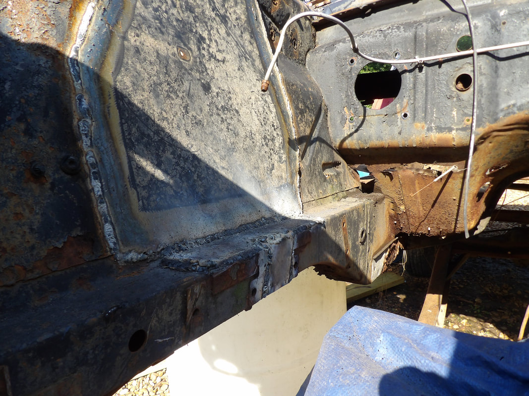
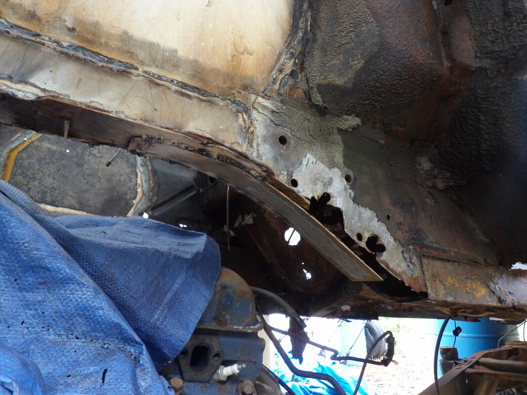
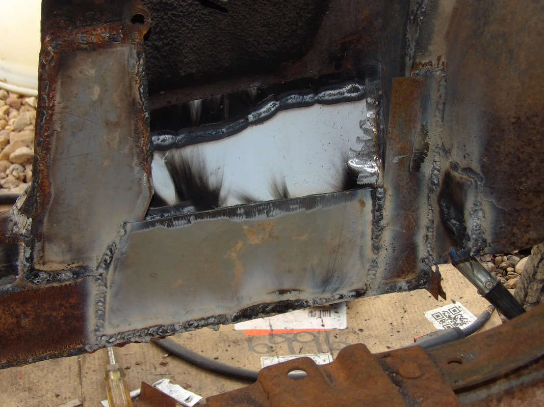
Now that I'm in the rear of the car, I had to start cutting out sections of the floor. I started with the area around where the rear shock and the highest point on the Ranger frame made contact with the bottom of the Mustang floor. After that was cut out and the first fitting done, I found several other spots I had to cut out. Two crossmembers on the Ranger frame were making contact with the floor, requiring more cutting. Eventually I made it to the point where I cut out enough floor sheet metal that the crossmembers and the main frame rails were clearing enough for the Mustang body to sit lower on the frame. I also had to cut out some of the trunk sheet metal around the edges of the hole where the fuel tank would go to help in clearing the frame rails at those points as well. With the body down pretty low, I put a level on the rocker panel to show that the body was indeed level. Looking at it, the body was just right front and back. I didn't need to cut out any more material to lower the body. At this point I just cut out metal that was below the tops of the Ranger frame rails. Reason for this was when I do start welding in floor patches, any metal that is below the tops of the frame rails will end up just being extra metal that will possibly get in the way if any work needs to be performed underneath. I had to cut some metal from the front seat mounts at the rear as well. The way things look, with the way the body rides high, the driveshaft hump won't be in the path of the driveshaft, so I could possibly cut out the hump metal and weld a straight piece of angle iron across the rears of the floor pans to reinforce the front seat mounts. The next order of business is to fabricate mounts for the rear as I did on the front.
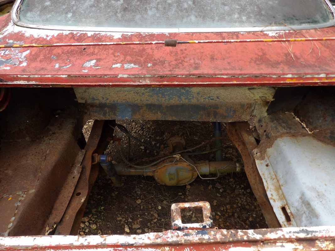
The trunk floor area with some of the metal cut out to allow for the rear most parts of the truck frame to clear the Mustang body sheet metal.
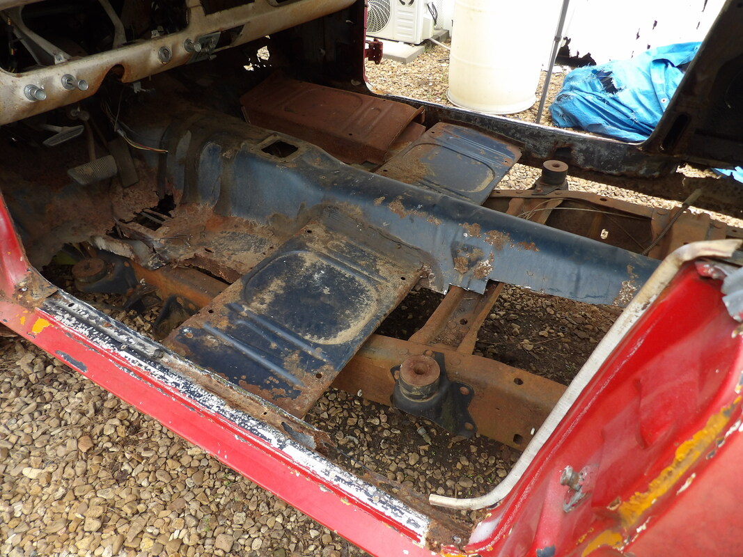
Extra sheet metal cut away from the floor pans to clear away sheet metal that is lower than the Ranger frame rails. New sheet metal and reinforcement iron will be welded in place to close in these spaces to make the floor even and complete.
The body showing how its level on the truck frame after the weight reduction that was made.
The rear sits nicely on the frame with no real gapping between the rear panel and the truck frame crossmember.
With the front body mounts taken care of and the flooring cut out enough to allow for the proper clearance to get the body at the level we're seeking, I moved to make a body mounting member for the rear. Since the rear is just the trunk floor sheet metal, I had to come up with something that would capitalize on the use of the rear subframes while being able to attach to the rear of the truck frame via a couple holes in the rails. I also had to be able to still use some rubber for cushioning so the rear doesn't undergo metal on metal contact that could compromise the integrity of the body. I used a long piece of angle iron and long 1/2" bolts to make a member that would extend through the trunk floor sheet metal and bolt to the truck frame with rubber added to aid in some cushioning. The biggest cushioning comes from rubber that is sandwiched between the truck frame and the bottom of the body where the two make contact. The rear mount member is welded to the sides of the trunk where the panels attach to the rear subframe to ensure the maximum amount of strength in this area of the body. With the rear member made and the rear of the body officially mounted, I moved to the pair of intermediate body mounts under the firewall. I had to make a couple more mount members that would be welded between the sides of the front subframes across to the body where the door hinges are mounted at. A long 1/2" bolt welded to the angle iron that makes up the member with a washer welded a couple inches from the end of the stud allows for a rubber piece to be installed for a cushion where the stud extends into the Ranger frame body mount. Once these members were made and installed, I was able to move to the interior, cutting out more old floor sheet metal to ready the interior for the new arrangement of flooring to make up for the idea that the Ranger frame rails extend up higher than the old Mustang floor pans. I had to weld a new floor pan in place on the passenger side where the pan attaches to the firewall. From here I cut some patch metal and welded these along the inner rocker panel area extending back to the rear quarter, attaching the rear quarter and door jamb to the patch metal, restoring the integrity of this one area. I'll still have to add more metal later to fully close in these areas, as well as patch the rear quarter, but right now we're off to a start with getting the body back whole again. I also started with the let side front floor pan where it connects to the firewall, but in this area I had to do more work as the holes for the steering column and accelerator pedal had to be taken into account, as well as removing the accelerator pedal assembly. I also had to take into account the parking brake cable that passes through the floor in this area. I had to trim down the new floor panel to prevent my having to do more precise cutting and welding. Since we're not going for a high end resto but more of a functional build, I'm not going to stress on the neatness of the edges of the panels and the resulting welds due to the other areas that are kind of tacky in their quality. Again, function over aesthetics.
Rear body mount member made from a piece of angle iron and long 1/2" bolts welded in place.
Shot of stud from body mount member passing through trunk panel and into truck frame with rubber cushion in place.
Rubber pieces inserted under the rear shock tower body where it made contact with the top of the Ranger frame. Once the body was fully lowered down, the rubber was sandwiched between the two metal surfaces.
Angle iron body mount member welded in place. Besides being welded on either side to the trunk sections where they attach to the subframes, its welded along the back which makes up the taillight panel and rear panel where the bumper goes. Extra metal was added along the rear of the angle iron to allow for more complete welding.
Right side intermediat body mount member welded in place after construction of piece.
Right side front floor metal cut out from around subframe and supports going up to firewall. This is in preparation for welding in the replacement floor pan.
New floor pan welded in over opening. Extra pieces of metal had to be welded in place to make up for gaps that were present after some miscalculations in the cutting of the old metal.
Extra floor pan metal cut out around the rear area. Since the Ranger frame rails ride higher than the old Mustang floors, I'll have to weld new floors in at a higher level to ride over the truck frame rails. Hopefully I'll be able to still install the rear seat and side panels.
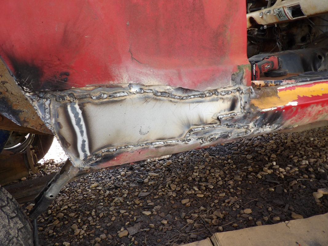
Patch metal pieces welded in place along the inner rocker panel area and door jamb and connecting to tire well. More metal will be added later when I add some patch metal to the rear quarter panel over the opening that is present between where the rocker panel and quarter panel meet.
Old floor pan metal cut out in preparation for welding in the new panel. Extra metal will need to be added to fill gaps that will be present since we couldn't get a perfect cut around the top area where the contours and holes are all present.
Front floor pan welded in place. Note the extra metal that's welded along the outer edge to fill the gaps that were present, along with the extra welds around the bottom of the steering column tube.
With the intermediate floor pan cut to fit (more or less), I took a moment to tack weld the front of the panel to the front floor pan, then make other cuts to allow me to manipulate the metal to make the pan fit better in the opening. I accepted the idea that I would have to weld in small pieces of metal to fill gaps in the metal where the pan sits. As I made welds in different spots, I manipulated the metal a little more, adding more welds to get the pan to sit the way I wanted it to sit. As the final placement of the pan was established I was able t make more complete welds along the seams, having to add metal in the gaps that were made, especially along the inner rocker panel seam, on the outside edge of the floor pan. Once this was done I was able to move to the right side to begin making a replacement intermediate floor pan for that side. I took a scrap piece of metal and eyeballed the amount of metal I could cut off to begin the shaping of the pan to fit. At first I was going to keep the old seat mount pan on the right side but after trying to grind the rust off, I found that this pan was really weaker than I gave it credit for. Since I have another seat mount pan, I went ahead and cut out the old seat mount pan and took the new pan and cut the notch I would need in order to fit the pan over the Ranger frame rail. With the new floor pans read to go, I ground the edges where the pans will be welded to bare metal in preparation for welding. I left the back portion of the seat mount pan in order to hang on to the rigidity of the seat mount. I'll still add a piece of angle iron to this area as on the left side to provide a solid surface that will add to the strength of the flooring in the body. With the pans all welded in, I can move on to the left side inner rocker panel and angle iron which also includes the last set of body mounts.
The intermediate floor pan after welding is completed. Note the extra metal welded in place on the inner rear corner of the pan where the corner was cut to help in placement of the pan.
Front seat floor pan welded in place on the right side, along with intermediate floor pan piece connecting to front pan piece.
Piece of flat stock welded in place under the intermediate floor pan from the inner rocker panel across to the front subframe. This will keep the floor pan from vibrating and making excessive noise in the cab.
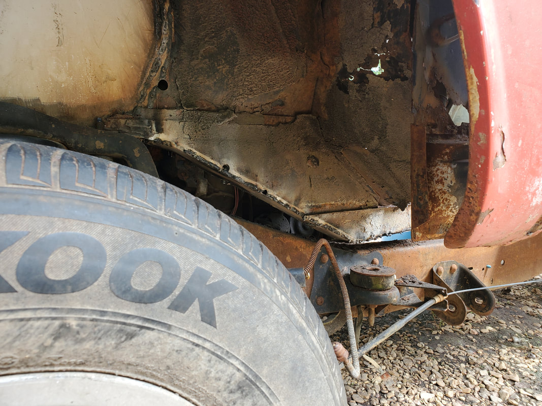
With the front third of the floors taken care of, I took a moment to make some repairs to the inner rocker panel section going back to the rear quarters and tire wells. This would involve welding some rigid sheet metal pieces over the areas where there used to be metal connecting the tire well and the rear quarters. At the same time I added this metal, I also took a moment to do some crude patching to the rear quarter panels by doing some shitty welds to some pieces of sheet metal to fill the large holes that were present on the quarter panels. The right way would've been to cut out all of the quarter panel and weld in patch panels but we don't have the money to buy these components. We're trying to do this build on a very low budget. With the patching on the body taken care of, I welded on the angle iron pieces that would reinforce the seat mount panels and provide the mounting point for the last set of body mounts. A single bolt was welded to the rear pair of angle iron pieces so they would pass through the body mounts to be secured with a piece of rubber hose acting as a washer to add a light cushion between the angle iron piece and the body mount. Once the angle iron was in place, a pair of small pieces of sheet metal filled the gap between the angle irons to further close in the floor. From here, I cut a couple pieces of conduit to add reinforcement points for the rest of the floor pans to be welded in. The first set of conduits went just in front of the Ranger frame crossmember and the second set of conduits were slid within one another and routed between the tire wells and under the driveshaft hump. With these conduits in place I was able to weld in the six pieces of sheet metal cut to provide the floor pans needed to fully close in the car's interior.
Extra pieces of rigid sheet metal welded in place to connect to the rear tire well. Note the small piece of metal covering a hole on the tire well where it connects to the inner rocker panel area.
Wire channel in the door jamb area had to be replaced with some scrap metal due to the rust. Note the small patches in the door jamb to fill in the holes made by the vacating metal.
Crude sheet metal patches welded in place to fill in the holes present from the rust. Note the smaller patch on the rocker panel. The area will be ground down some and prepped to be covered in body filler in order to smooth out the whole area to make it look somewhat decent, as far as body repair is concerned.
Patch pieces had to be welded in to fill holes present on the tire well as well as replace rusted metal on the fender lip.
Sheet metal patches welded in place on rear quarter panel.
Right side tire well and fender lip patched up as well.
Large piece of rigid sheet metal welded in place to close the gap between the rocker panel and tire well area. Note the rear quarter panel patch welded in from the inside.
Shot of the nut and washer on the bolt that was welded to the angle iron. Large washer was welded to the Ranger frame body mount to create a solid spot for the bolt to pass through without the concern of the angle iron and bolt on the body being able to move around.
Door jamb area filled in with small pieces of metal to close in a hole that was present in this spot. These areas can only be painted over as there's no real way to smooth this weld out.
Shot of driver's side angle iron showing where the pieces weld to the sides of the driveshaft hump instead of passing through to the other side. Lack of angle iron long enough to cover the gap between rocker panels from driver's to passenger side caused me to have to use two short pieces of angle iron welded to the outside of the driveshaft hump.
Driver's side sheet metal welded in place between the angle iron supports. Note sheet metal welded in place on other side, as seen at the upper let of the picture.
Both sets of conduits welded in place.
Front sets are single pieces welded to either side of the center hump. Rear most conduit piece is made up of a piece of 1/2" and piece of 3/4" conduit slid inside of one another. This set of conduits is able to pass under the driveshaft hump to be welded to either side on the tire well panels.
I went off on a tangent for a little part of the car that had been concerning me as I was cutting into the floors. The two interior panels that span either side of the rear seat would no longer fit in place in their original form due to the higher placement of the floor in the rear area of the body. I already figured I'd have to trim these panels to make them fit, otherwise I'd have to come up with an improvised interior panel that would make the interior look bland. I decided to trim the panels. I did some preliminary measurements to be able to see where to start and get a line drawn for making my first cut. After making that first cut and doing the first fitting, I was able to better eyeball where the bottom of the panel was making contact so I can make more precise cuts along the bottom so I can prevent my cutting too much material away and having the panels fitting with excessive gappage along the bottom. Once I had the panels trimmed to fit, I was able to fit the panel nicely to secure the screws along the top. As for the bottom, I had to use an alternative method to secure the bottom of the panels since the mounting point on the panels were cut away. I used an angle brace for this. One hole drilled on the panel and a nut and bolt held the brace to the panel. A hole drilled through the floor for a single sheet metal screw held that side of the brace in place. With that, I was able to secure the bottom of the panel to the floor. I did take a moment to splice a length of wire to the wire ends on the light socket in the panel so these lights can be wired in with the new wiring of the car later on. With all that done, I was able to mount the panels in place exactly as they were before any of this was started, minus the bottom part that was trimmed off to fit the new floors. I did the right panel first, but when I did the left panel, already knowing how much material I had to remove, I was able to get a starting point close to the final point so after the initial cut I only had to do some light trimming to get to the final fitment on that panel. With that, the interior panels are in place so I can reassemble the rest of the interior around these panels when I get to that point. From here we're going to move back to getting the body assembled.
Right panel is trimmed for the last time and fitted to the side. Mounting screws are able to be applied along with the angle brace that'll be used to secure the bottom of the panel to the floor.
After only having to make a couple cuts I got the panel to it like it needed to fit. The panel is secured in place with screws and also with the angle brace, noted at the bottom of the panel towards the rear of the panel.
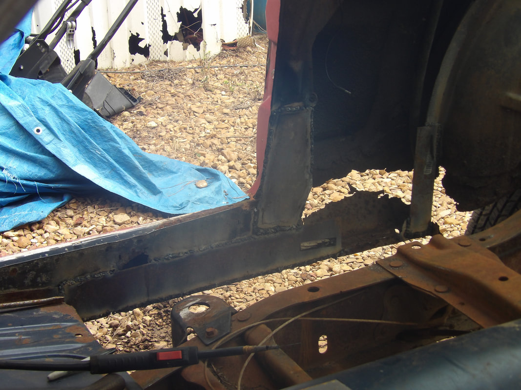
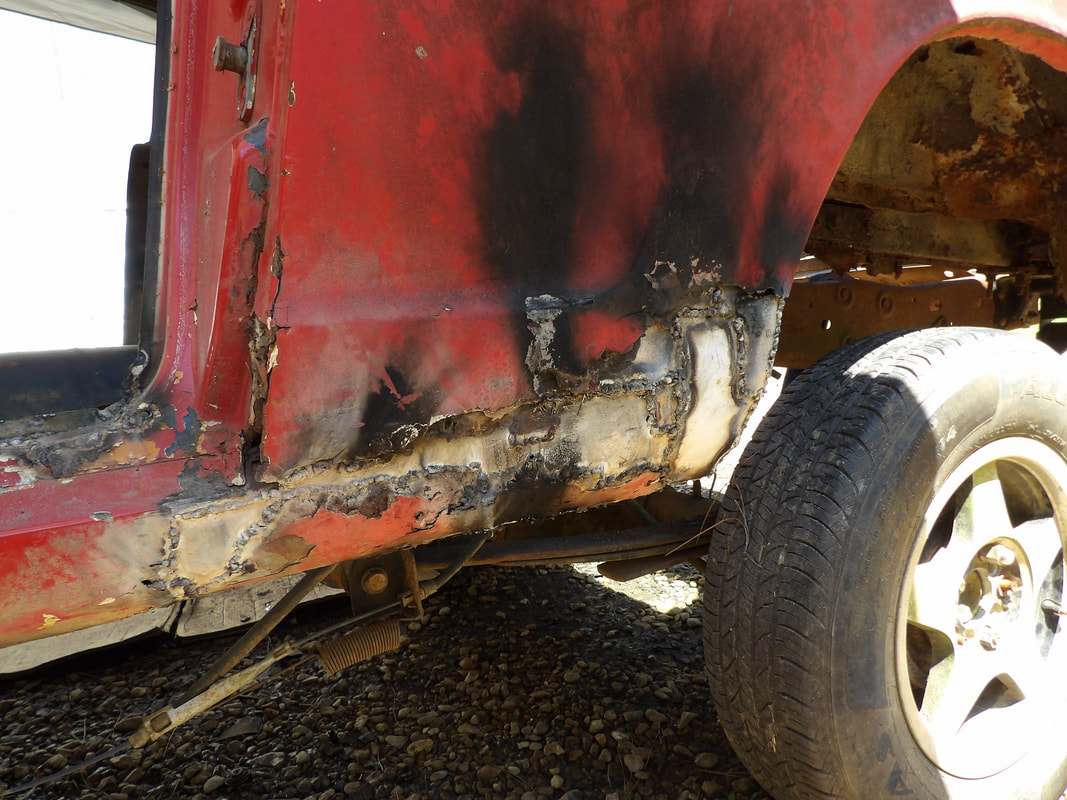
With the floors done on the car, the time has come to start reassembling the body. Since we already have the fenders on, I started in the rear. I wanted to get the rear valance in place. This would involve me having to trim some of the panel to allow the piece to fit in place around the rear of the truck frame, since the frame rails passed through the area where the panel would go. I also had to drill a couple extra holes to secure the top of the panel to the body. After getting the panel in place, I installed the trunk lid. I had to remove the torsion spring rod since the metal tab/lever on the right hinge that held it kept bending under the spring pressure. The absence of this spring did not affect the ability of the trunk lid to open and close, it just prevents the lid from springing up when the key latch is released. I also had to weld the bottom of the latch assembly to the back of the body in order to ensure the trunk lid would latch and sit flush against the body, which it did. The bumper went on with little fanfare. From there I moved on to the front. As with the back, the front valance panel needed to be trimmed to fit around the frame rails. I also took a moment to weld the contact points on the intermediate panel that mounted over the valance panel, despite the panel being bolted to the valance. This welding allowed the panels to be manipulated to a straighter position so once welded, the whole panel from right to left was straighter than if nothing was welded. The grille/headlight assembly was also attached, with the headlight trim pieces. I had to install the hood latch assembly in order to secure the grill to contact points on top of the assembly. As for the bumper, I had to take the old bumper mounts and trim them to allow the pieces to fit in the areas of the subframes where the front body mounts were made, then weld the mounts in place. After verifying the bumper would sit with a decent spacing from the intermediate panel, I welded the mounts then bolted the bumper in place. Everything sat nicely, restoring the front body back to a point where it hadn't been since before I stripped the body down.
Rear valance panel installed after making notch cuts to fit around truck frame rails. Panel is secured with sheet metal screws along top and at corners. Bumper is held in place with standard hardware into the back panel.
Trunk lid installed after bolting to hinges. Torsion spring has been removed and latch bracket welded at bottom to hold lid in closed position.
Right door installed. Hinges needed to be moved back to allow latch to fit around knob on door jamb, despite latch not working properly. Work will need to be done on latch.
Left door installed. Hinges did not need to be moved here but the latch on this door is also not latching so work will need to be done on this door as well.
Front valance and intermediate panel attached, with welds between the two to make them one piece. Grille/headlight assembly also installed, fully bolted to front of fenders with headlight trim pieces installed. Headlight buckets needed extra screws to hold them in place due to old attachment points being rusted away.
Bumper mount fitted next to section of subframe where front body mount is located. Metal will need to be trimmed from these mounts to allow them to fit flush against what remains of the subframe so they can be welded in place.
Bumper is bolted to the mounts after they were welded in place to the subframes during the fitment of everything. Spacing around the bumper is at an acceptable point.
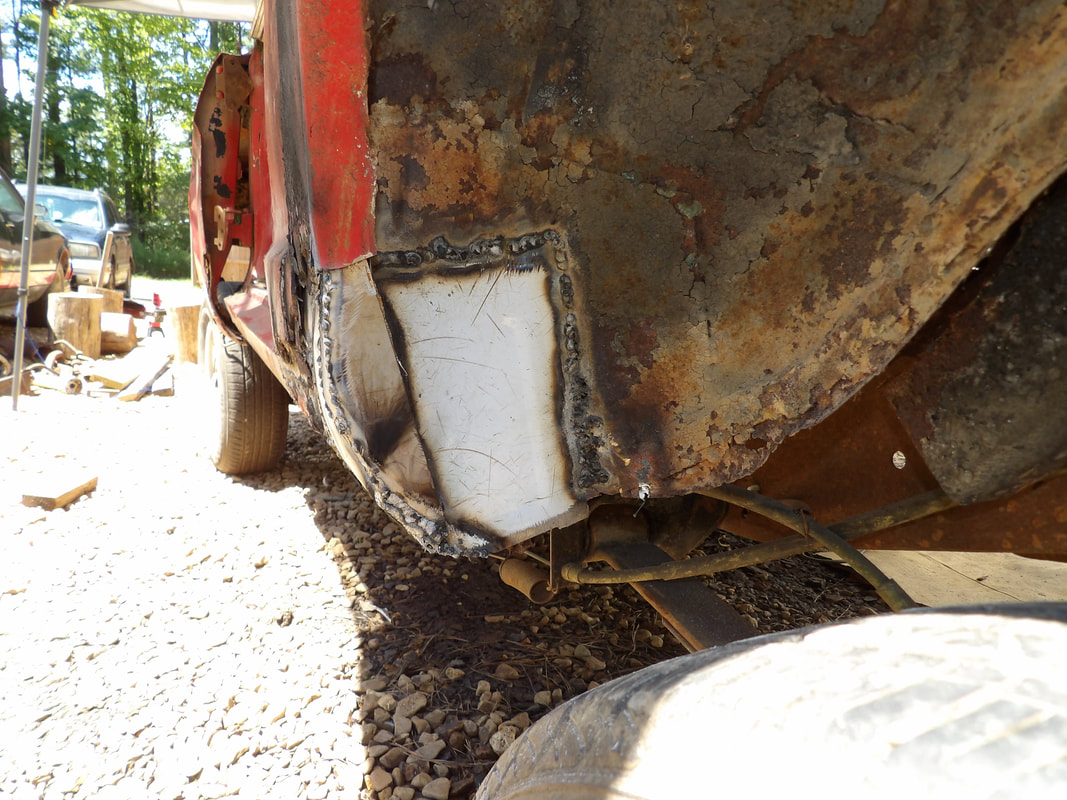
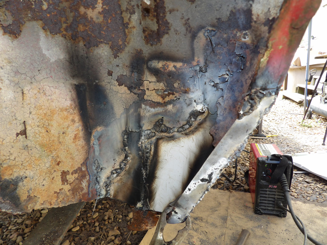
With the body panels back on the car the next order of business was some more crude panel patching. The fenders and the rear portion of the rear quarters had more rust hole areas that needed attention. Just like on the front part of the rear quarters, I prepped the areas and welded in some patch sheet metal, filling in the large areas that were missing from the panels. The driver's side was particularly bad, with a large part of the fender missing, a small section of the front of the rocker panel and even a portion of the bottom front corner of the door skin pulled away, all of which required patch welding. The rear quarters had to be welded on the outside as well as in the tire well areas. Once that piece of intricate work was taken care of, I pulled the door panels off to see what was up with the latch mechanisms. After liberal greasing with WD40 and simple working of the linkages and mechanisms, I finally got the doors to latch properly. The release levers and buttons on the inside and out, respectively, all worked fine as well. The lock knobs worked fine as did the key cylinders. I had to work the window crank mechanisms to get them to go up and down properly. The driver's side was rougher, and still is, compared to the passenger side but a little lubricant on the tracks and mechanism helped smooth things out despite the roughness. In the future all this stuff will end up being replaced. But in the meantime, the doors are able to work as do the windows. With the exception of the huge hole in the trunk where the fuel tank would go, the car is pretty much dried in.
Small sheet metal patch made on right fender at the rear where rust ate away at a portion of the old sheet metal. These areas will eventually be smoothed out and covered in bondo then leveled off to make the surface flush all across. Tabs made from smaller pieces of sheet metal were used to attach the bottom of the fender to the inner body structure with sheet metal screws holding the tabs at the bottom of the fender and on the inner body.
The left fender is worse off with more old metal eaten away, requiring a larger piece of sheet metal to cover the patch inside. Some of the metal was folded into a couple tabs that were used as anchors to hold the bottom of the fender to the inner body structure via sheet metal screws.
Patch made from sheet metal on front of rocker panel. This patch was welded almost flush with the old sheet metal due to the inability of putting the sheet metal in from the inside. Extra bondo will have to be used to level off this area, after grinding the weld beads as smooth as possible.
Back of left rear quarter panel with patch welded in place. After grinding weld beads, bondo will help level off and smooth the surface. Extra metal was welded in the tire well to fill openings made by rust.
Right rear quarter wasn't as bad as the left. A smaller patch is welded in place around the lip of the tire well. Extra patch metal was welded in the tire well to fill rust holes around this area as well. Undercoating will most likely be used to cover the surfaces in the tire wells to protect them from further moisture and subsequent rust.
Door panel removed from passenger side door while working on the linkages and latch mechanism in our attempt to free everything up.
Passenger door is latched shut and window rolled all the way up.
As with the passenger side, the driver's side needed the same treatment. The window crank is rougher and will most likely be replaced when the door is replaced. The door panels will also need to be replaced due to degradation as they are made from a particle board.
At this point I started on the assembly of the interior. I dragged all the pieces that were left up at the garage down to the work site and mapped out my plan to get things back together. I started off installing the taillights and the fuel filler tube and fuel cap, which were the only exterior components I didn't install yet. As for the interior components, I took a moment to clean, sand and spray paint all interior pieces as part of an extra level of restoration. I could've just bolted everything back up but then the interior would look like crap. This way, with everything painted up, I can make the interior look 1000x better than even the outside looks. I even took a moment to prep and paint the seats as part of the overall interior restoration. The floors were painted with rubber undercoating, mainly as part of an insulation attempt, also because I couldn't source the enamel paint that I would typically use for painting interior sheet metal. The rubber undercoating will better insulate the floor versus simple paint, even though more than likely I'll end up covering the floor with carpet anyway. With the interior panels painted and installed back in place, I can move on to the other systems on the car that need to be done.
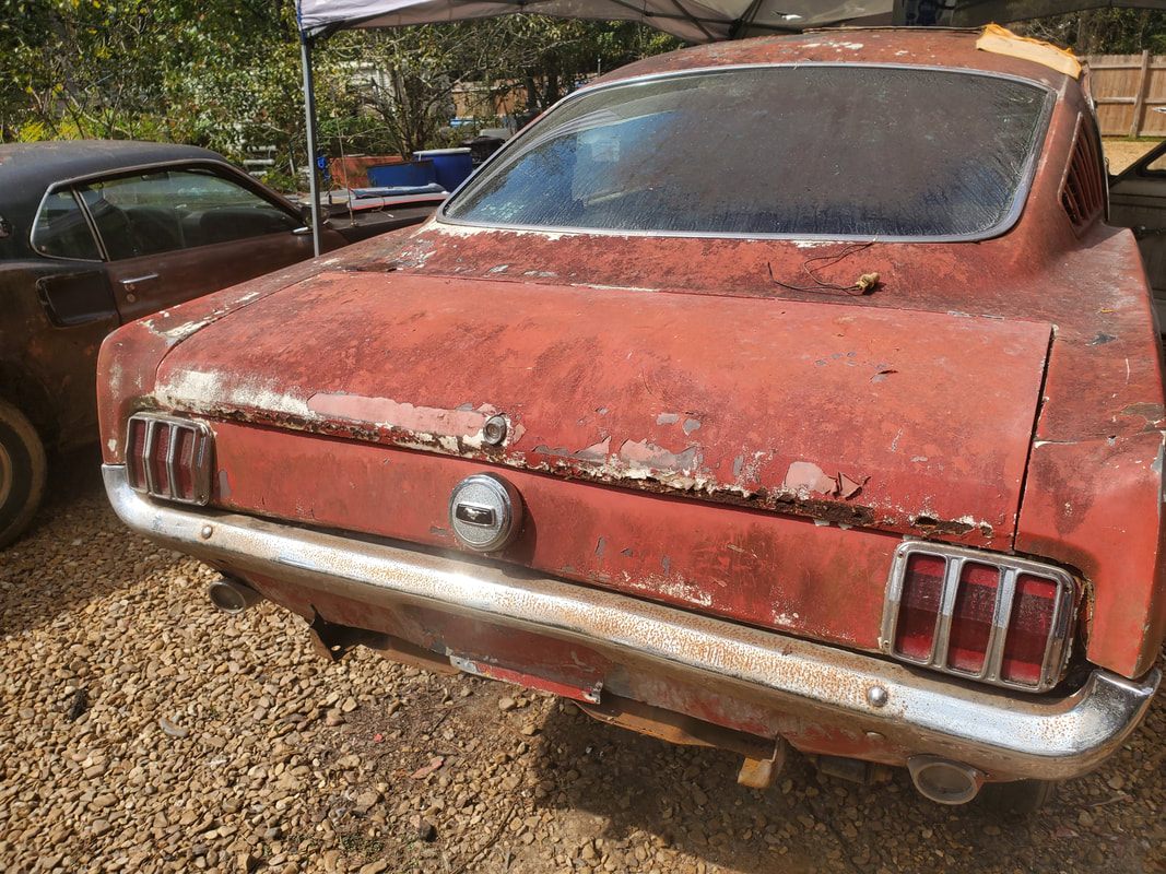
The taillight assemblies and fuel filler tube (unseen) and fuel cap in place. Fuel cap is a locking cap and metal trim around outside of the taillight lenses are held in place with long sheet metal screws all the way through the taillight panels to hold everything together.
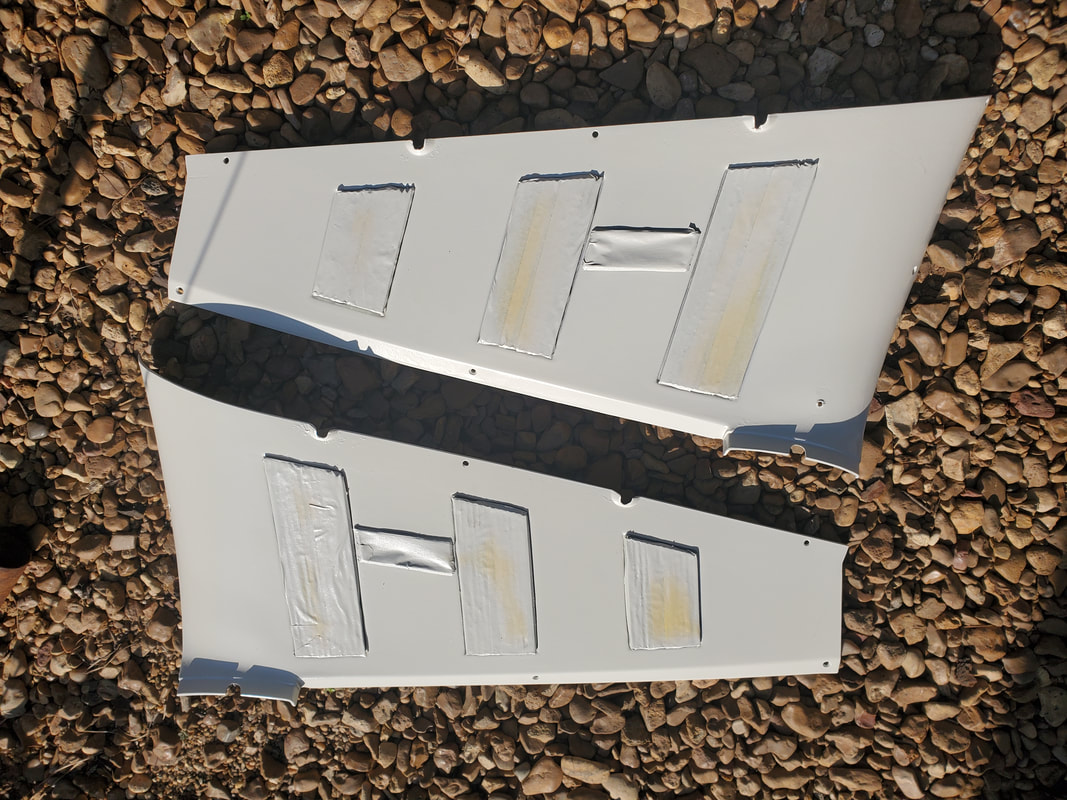
Upper rear interior side panels masked off and painted prior to installation. Paint used is Ivory Bisque, a shade of off white.
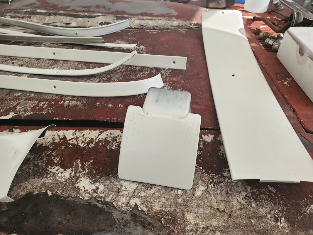
All the interior trim pieces, ash tray and a couple panels, all painted with a couple coats to ensure uniform coverage.
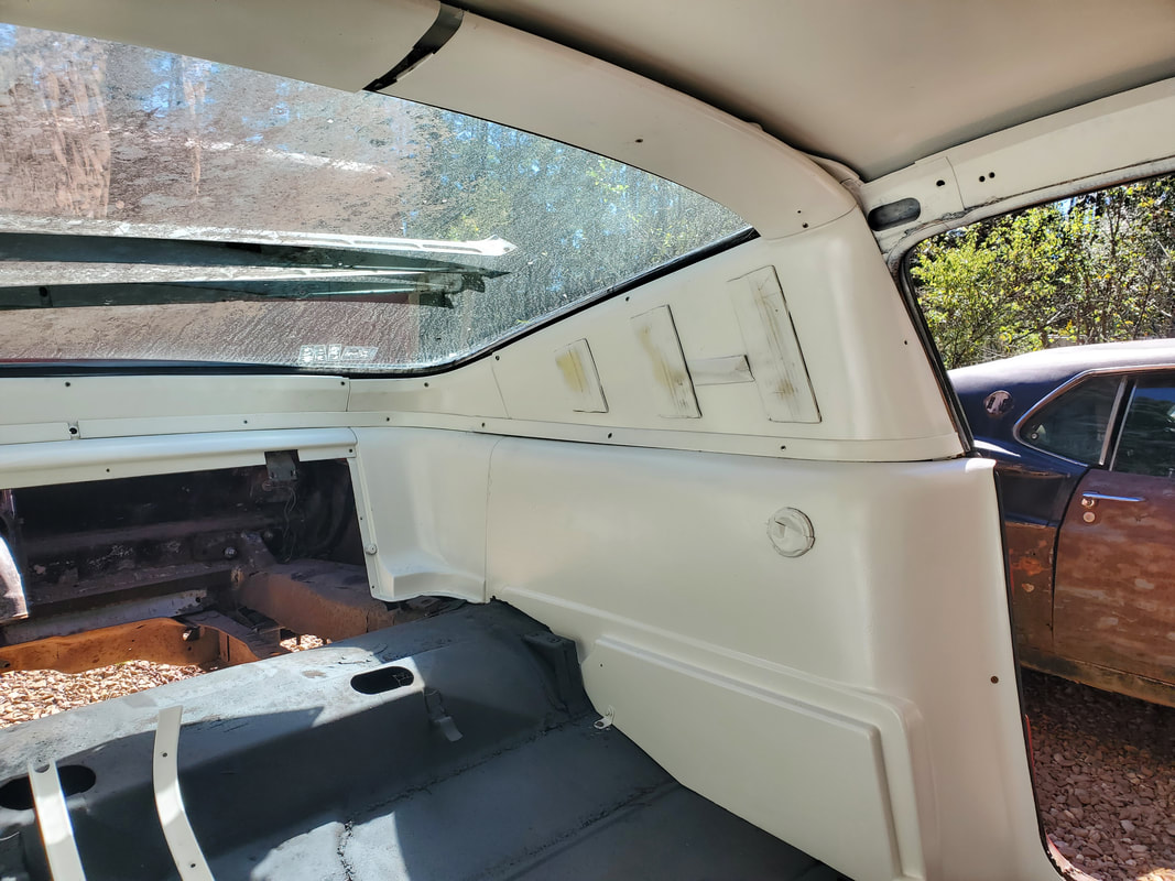
Rear side panel which was trimmed down to fit around new rear floors is also painted. Note the masked off interior light as well as the other interior panels and trim pieces all installed to cover up the rear.
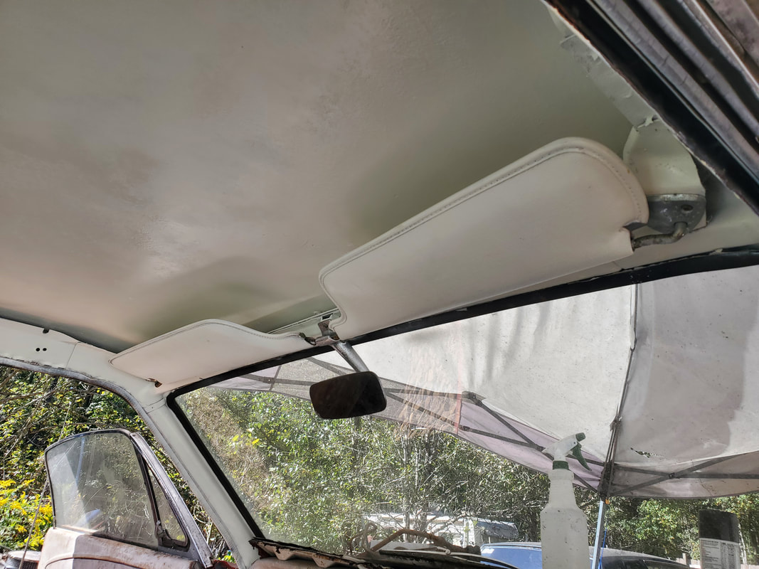
Front of interior with ceiling spray painted along with A-pillars. Sun visors are also painted along with rear view mirror. Mirror is painted with a metallic silver paint.
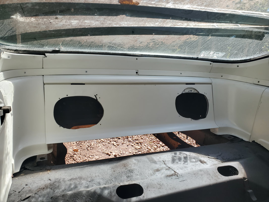
Speaker panel painted and bolted in place, with another view of the rest of the interior that is installed after painting. The old speakers have been removed to be replaced with newer speakers later.
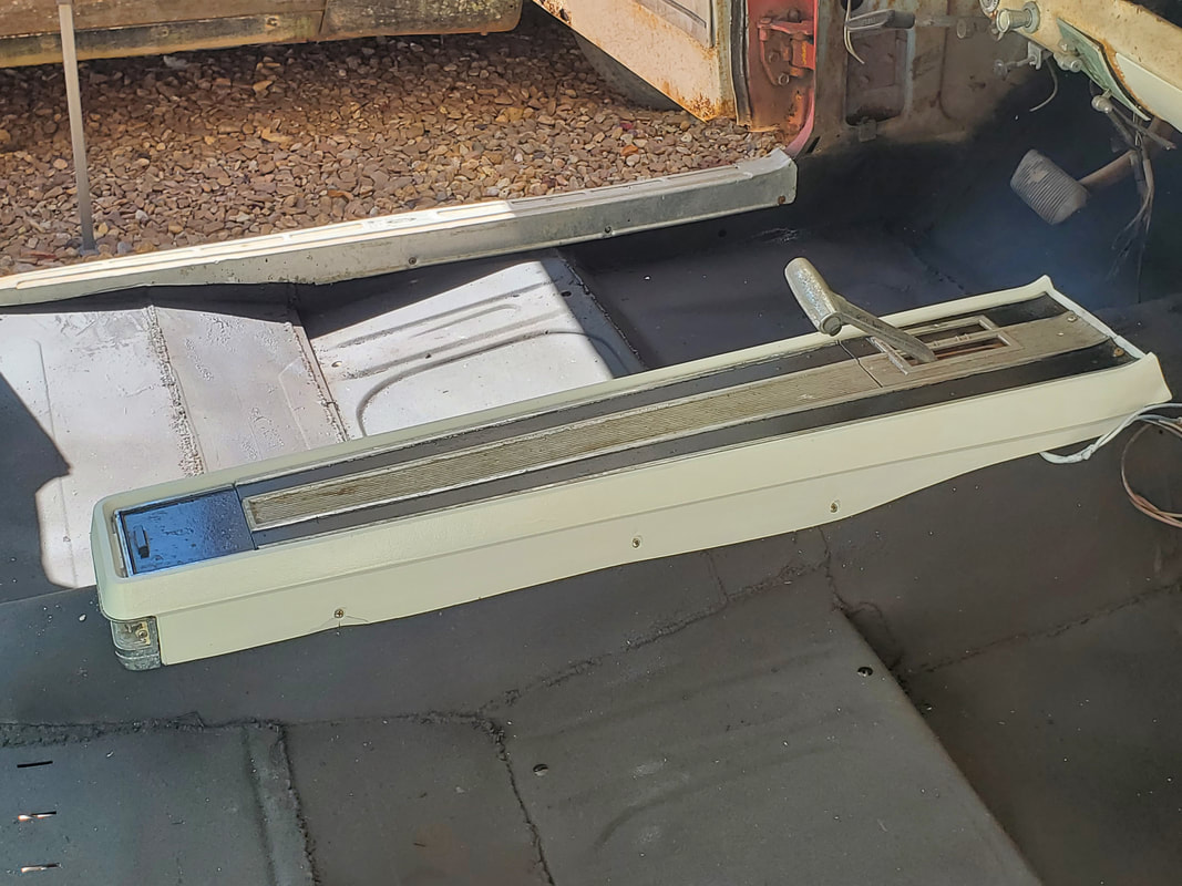
Center console also painted. Top panel is painted with some old black paint after masking the silver areas. Floor is also sprayed with rubberized undercoating for insulating purposes. After a few coats, the center console was mounted down. Also note the door jamb trim panel mounted in place. Same as the other side.
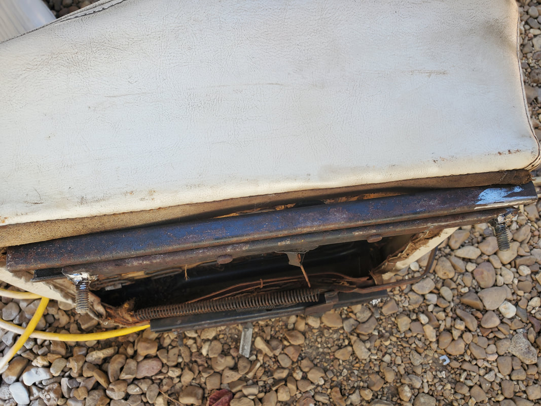
One seat was missing the mounting studs. Old stumps were popped out and bolts were welded in place to serve as new mounting studs. The other seat was missing one stud.
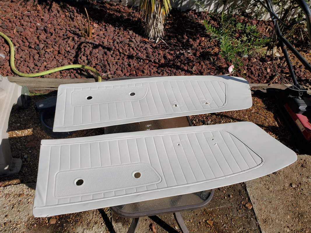
Door panels removed from doors and painted after masking off trim strip. These panels have a degraded particle board backing that would preferably be replaced with new board, otherwise new panels would have to be sourced.
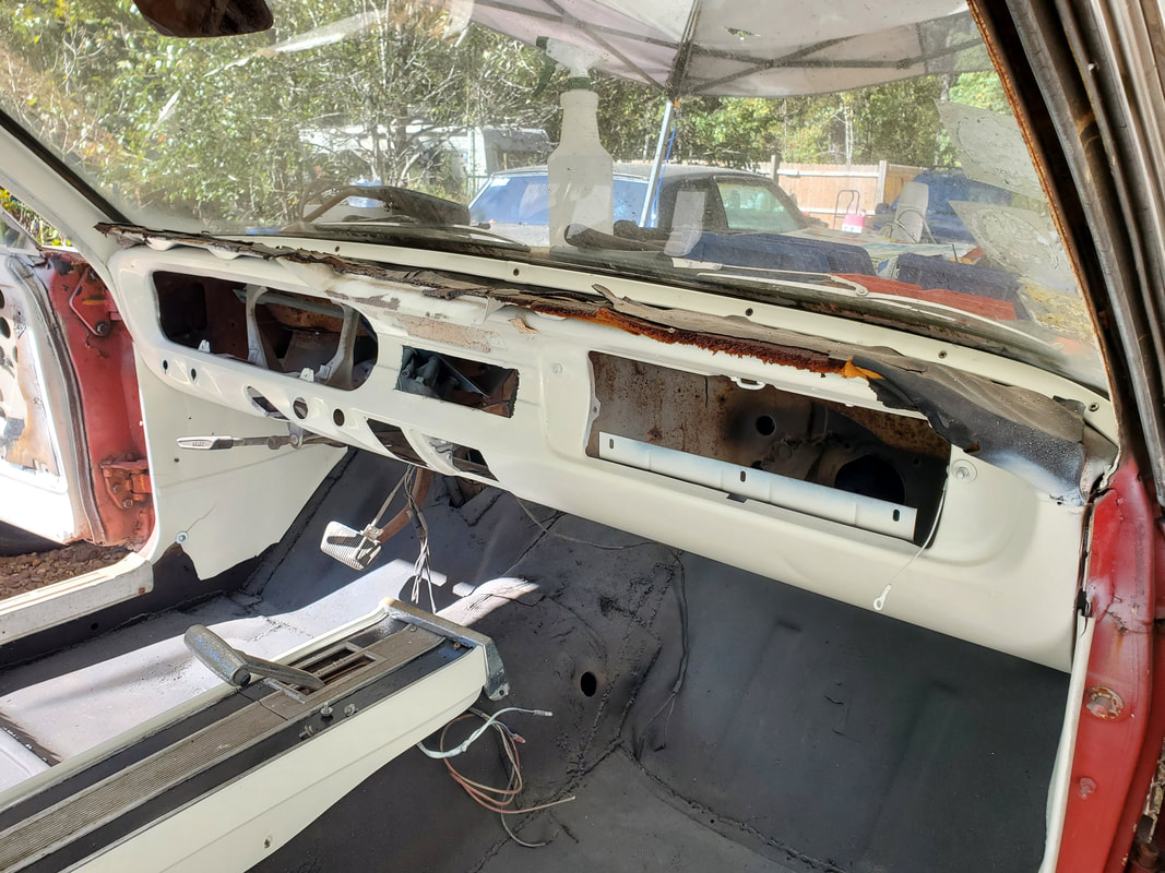
Dash frame spray painted after removing the remaining switches. After a couple coats dash panel looks a lot better.
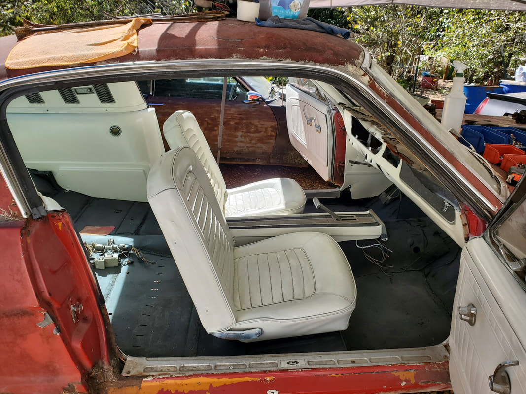
Interior fully assembled along with the seats, which were painted up just as well. The seats had to sit a while due to the paint not taking to the seat material as good as the other materials. After a few days sitting, the seats were not so tacky that I couldn't handle them during the mounting. Also note the doors that are also painted up with the panels back in place along with the window crank and door release levers.
With the interior pretty much done, I moved on to the steering column. This would be interesting in the sense that we're going to be coupling the remnants of the original Mustang's steering to the components of a Ranger truck. To do this I cut off the steering shaft from the original Mustang steering gearbox, since this was an integrated assembly. I picked up an intermediate shaft from a junkyard Ranger to hook up to the Ranger gearbox. I drilled a hole through the cut off end of the Mustang steering shaft and used a slightly smaller bolt on the intermediate coupling to hold the end of the shaft to the coupling. I also made a crude bushing for the steering column tube by welding a piece of 3/4" conduit to a large washer, which I then welded to the end of the steering column tube, after cutting some of the tube down. With all this done, I was able to mount the steering column tube, the steering shaft with the steering wheel attached, and the intermediate coupling, through the welded up bushing to complete the steering assembly. I'll have to add another bushing on the steering wheel side to help stiffen the wheel and eliminate the play that was present in the wheel.
I mounted a Ranger brake booster and master cylinder in place of the original hardware, which involved me drilling a couple holes to accommodate the studs on the booster. The left/right spacing was correct but the vertical spacing was not. I had to also trim some material from the brake pedal bracket to provide spacing around one of the studs. I was also able hook up the pedal rod from the brake booster to the pedal in place of the original pedal rod. I had a replacement brake line for the front brakes that I was able to hook up to the master cylinder but I need to get another line for the rear side, which goes from the master cylinder to the proportioning valve. With that done, I also took the time to install several miscellaneous parts on the engine that I had, like the Duraspark ignition system, voltage regulator and starter solenoid, radiator and a couple hoses. Once that was done, I installed the exhaust system. Using the old exhaust manifolds from the 73 Mustang, which included a length of pipe on each unit, I did some trimming and rewelding of the pipes to make everything fit properly. With a few hangers, I managed to get the entire exhaust system installed and spaced in a way to make the outputs even underneath the rear valance panel. I also needed to add the remote oil filter assembly I had picked up since the oil filter couldn't fit against the block in this current configuration. I also managed to get another brake line to finish the assembly of the brake system, even though we still need to bleed the system to verify the junkyard components even work. In the meantime, I started the rewiring of the car, with an aftermarket fuse box as the basis of the circuit.
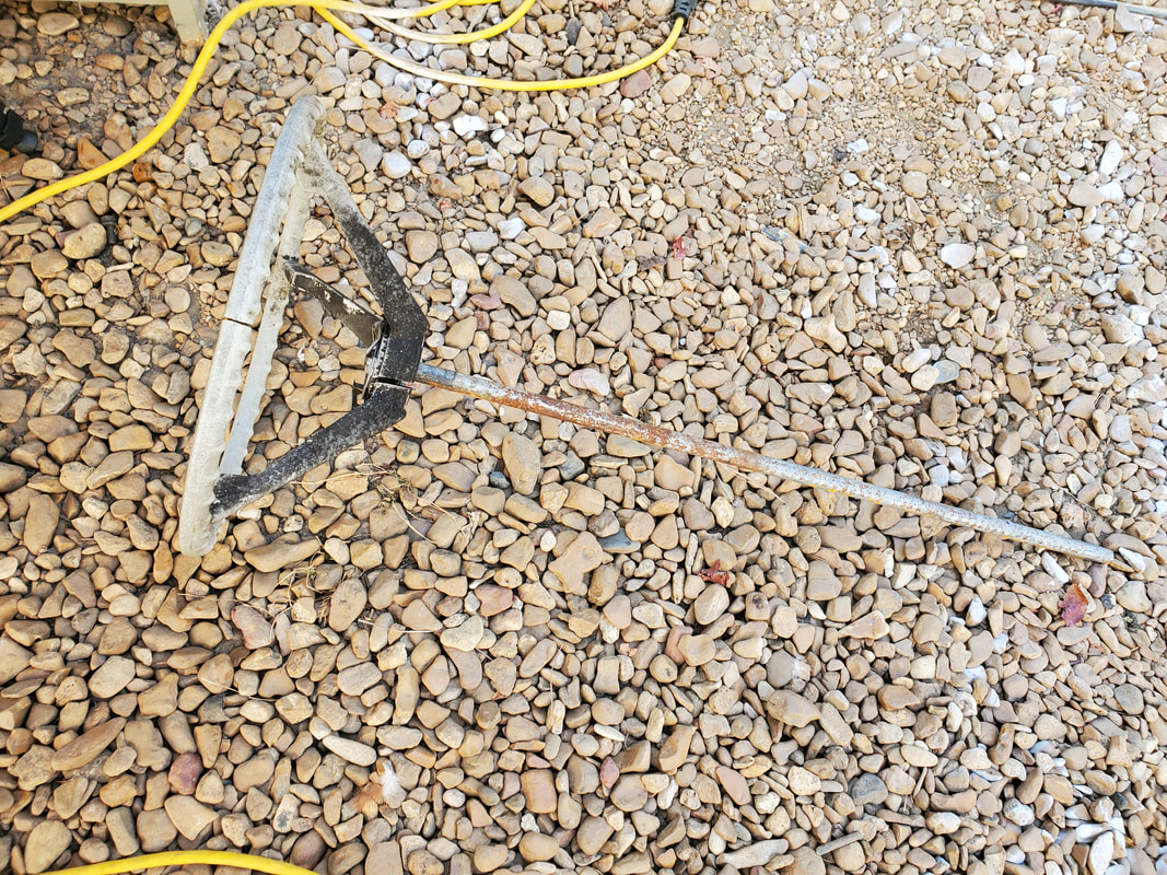
The cut off steering shaft from the old gearbox with the original steering wheel reattached prior to coupling to the Ranger intermediate coupling.
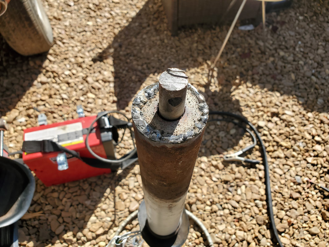
The makeshift bushing on the end of the steering shaft, made from a washer and a piece of conduit welded to said washer.
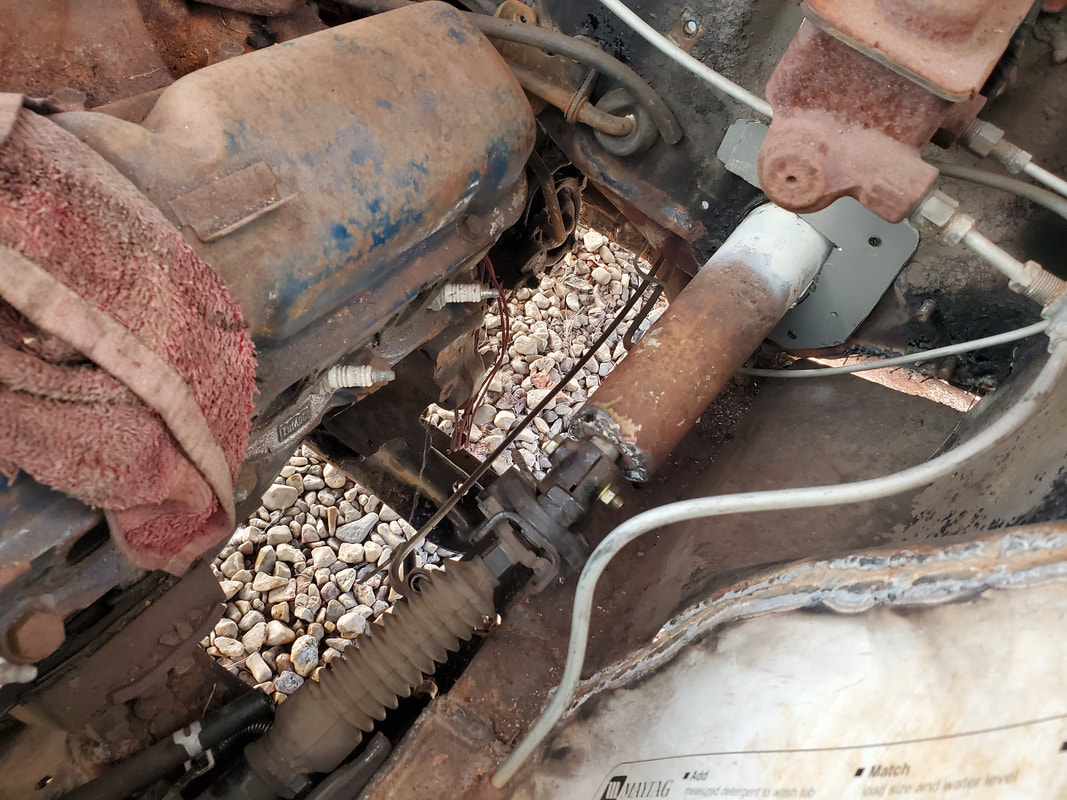
Steering shaft and column tube in place and coupled to the intermediate shaft. A piece of sheet metal cut to a U shape is bolted around the steering column to the firewall to hold the tube as stationary as possible.
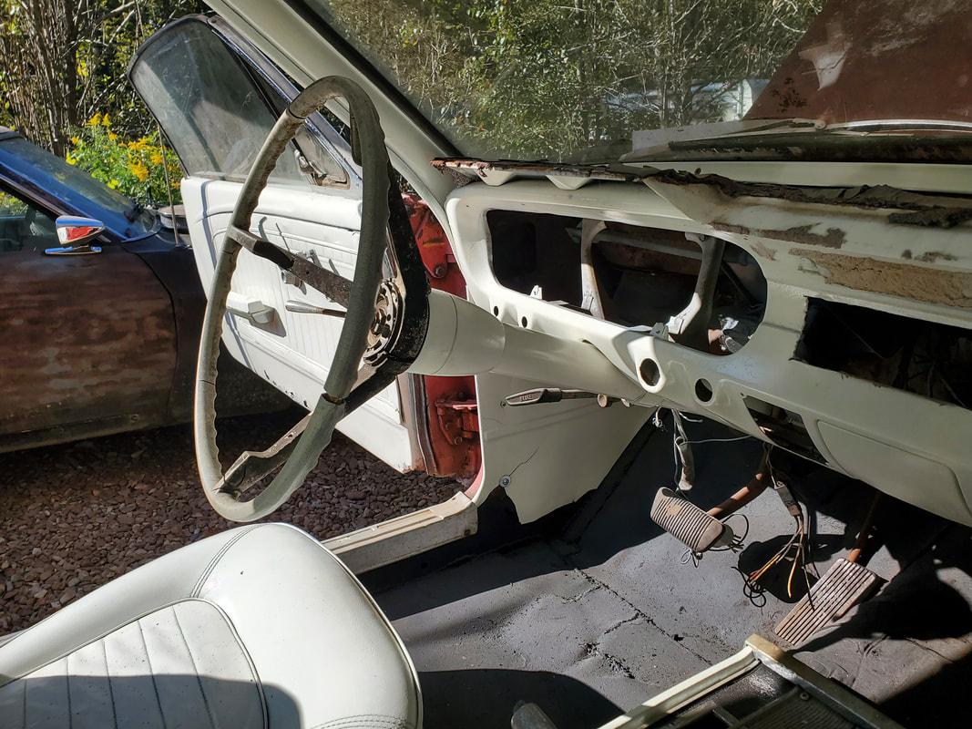
Steering column and wheel in place from the inside. The tube had to be mounted farther in to the dash to allow the steering shaft to be able to reach the intermediate coupling.
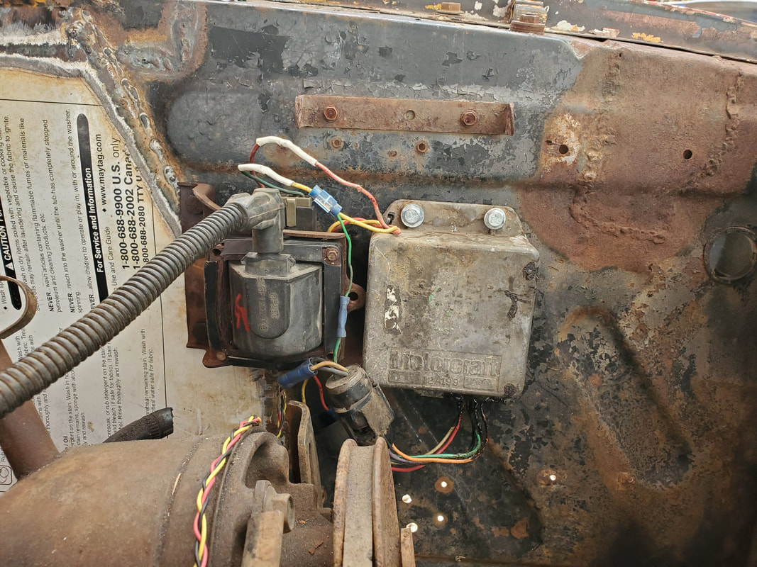
Ignition coil and Duraspark ignition module mounted to fender panel, note coil wire in place on coil and other wires in place.
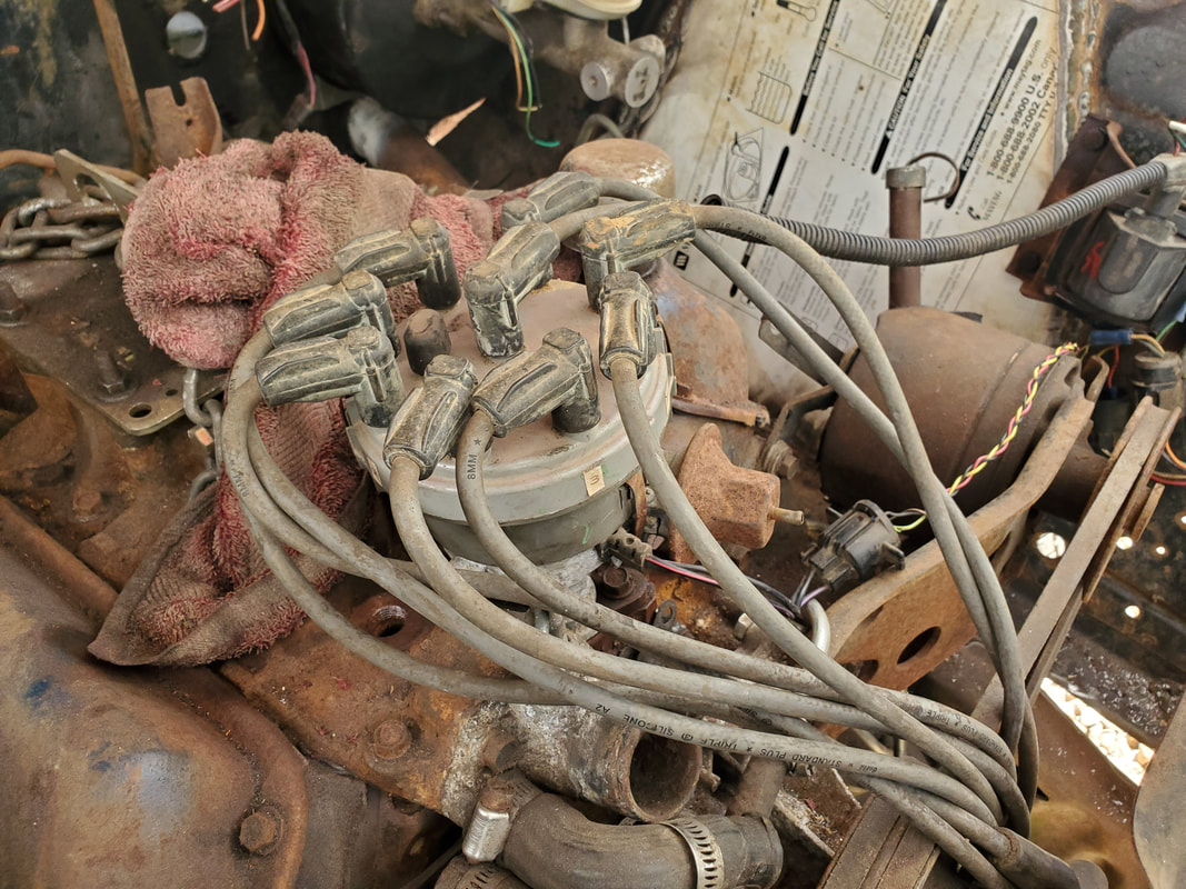
Duraspark distributor mounted in place with old wires still in place and wire harness hooked up to module Cylinder #1 will be determined during timing where the wires can then be properly arranged.
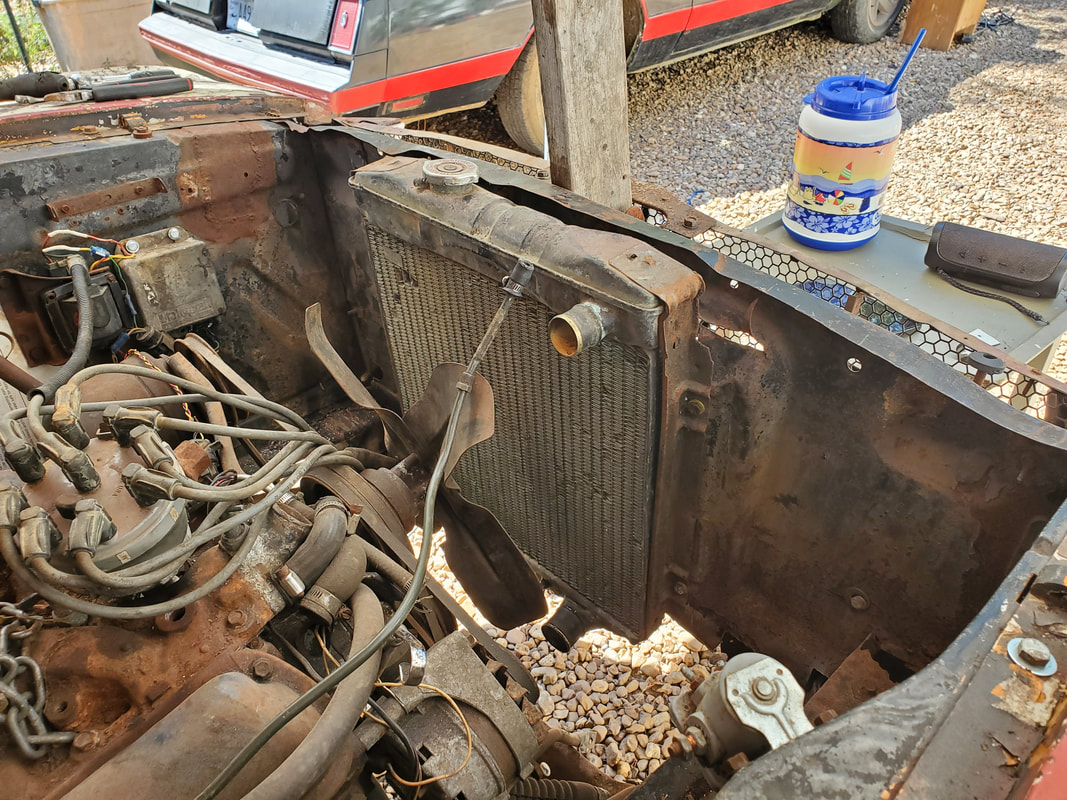
Radiator in place. I was able to hook up bottom rad hose and one of the transmission lines as they were still present on the engine/transmission.
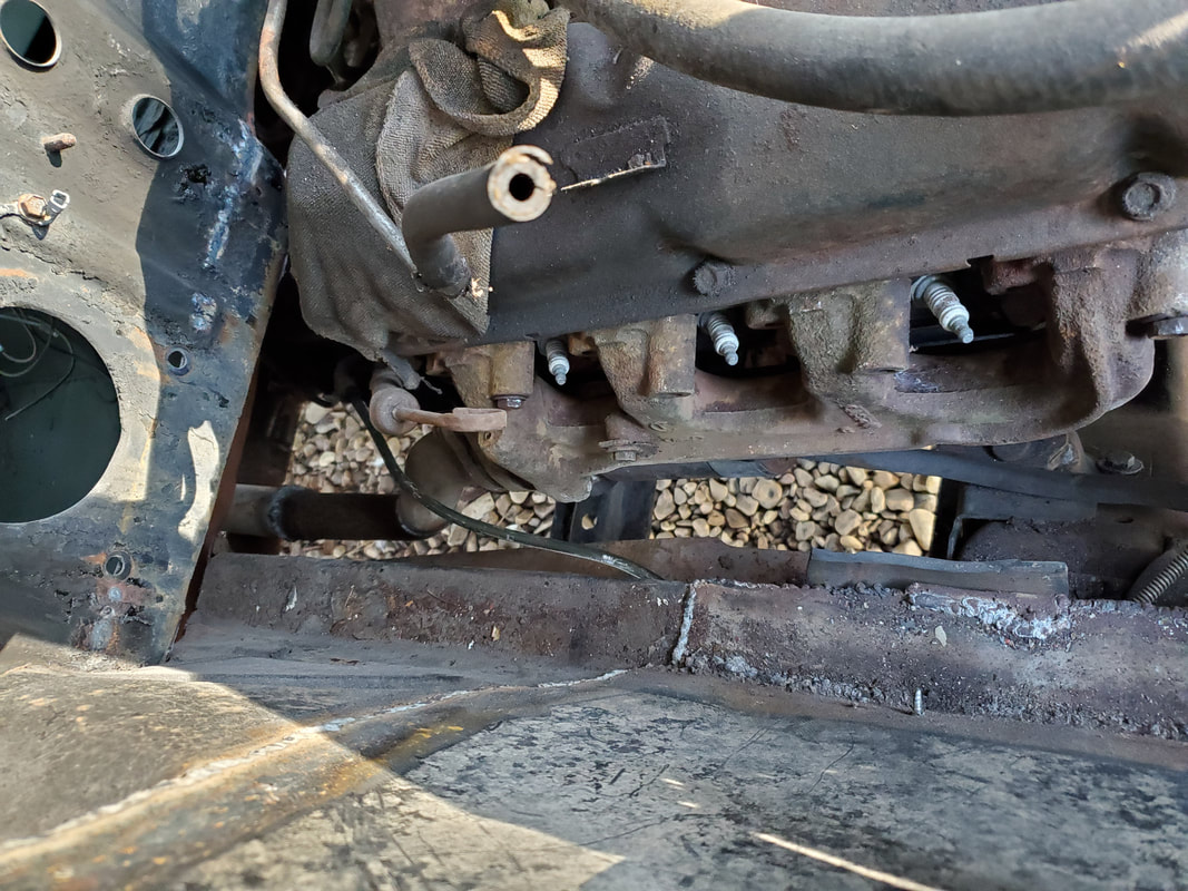
Right side stock exhaust manifold with length of flange/pipe bolted in place.
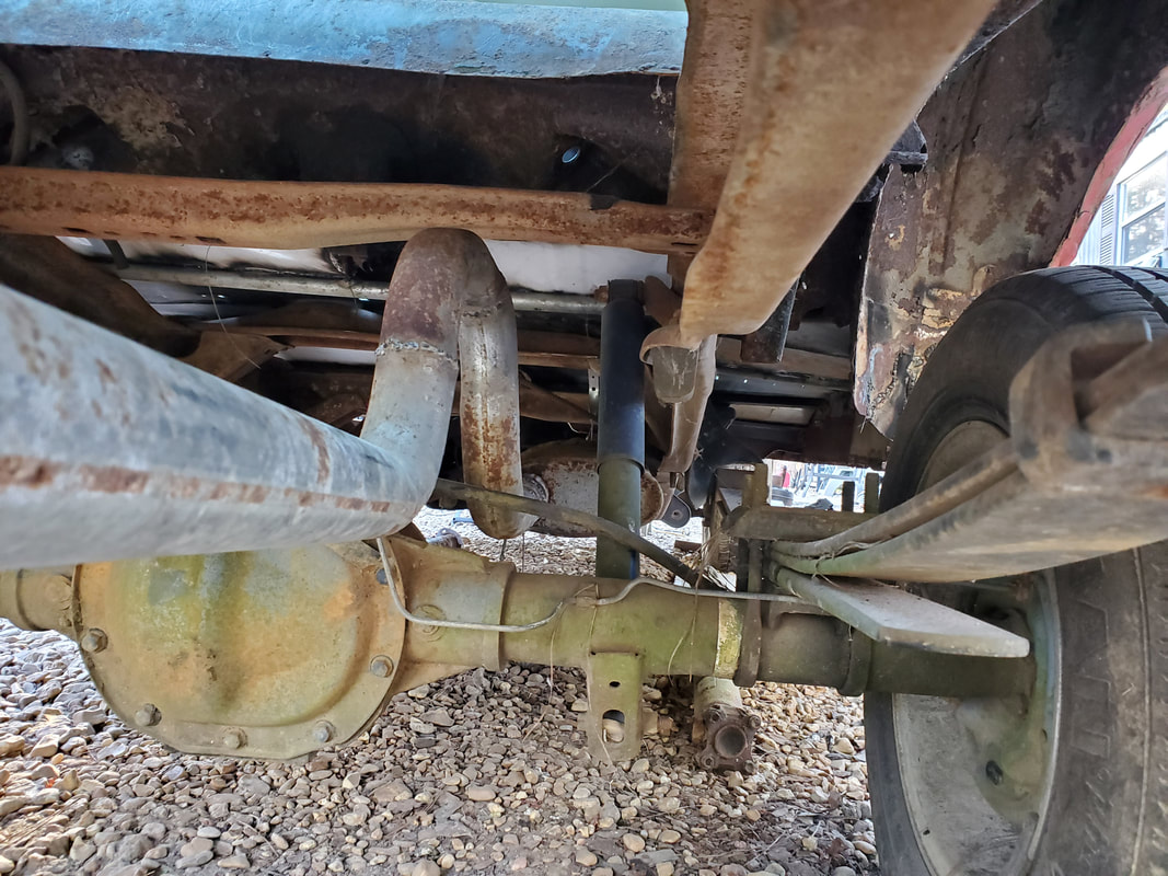
Right exhaust pipe with axle pipe in place. Several cuts and rewelds were made to make this length of pipe fit under the body.
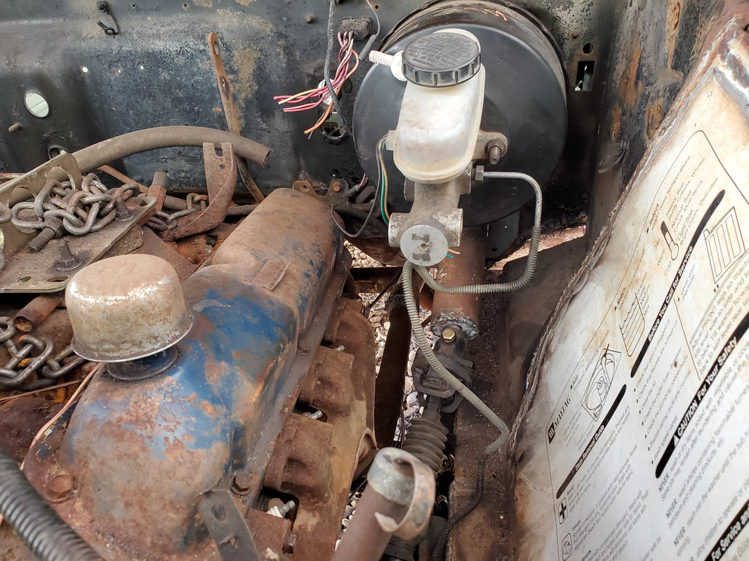
Left exhaust manifold in place, also Ranger master cylinder and booster are also in place along with one brake line.
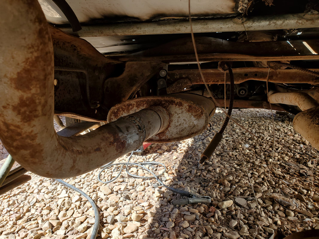
Left side muffler in place with axle pipe. Cuts and rewelds had to be made for this side as well.
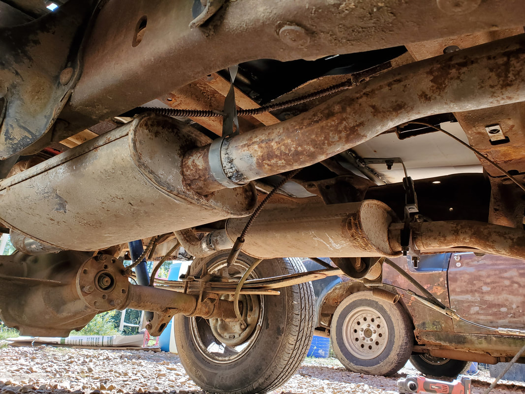
Another angle to the pair mufflers and pipes. Note the hangers holding the middle of the pipes to the underside of the floor.
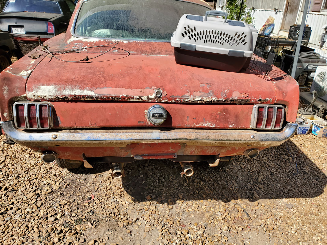
The outputs o the exhaust pipes under the valance panel. The spacing is closer than what would be normal on this car but its even nonetheless.
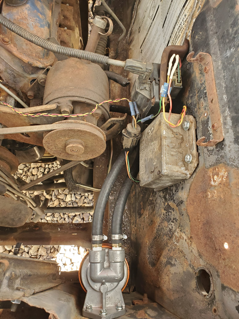
Remote oil filter base mounted to radiator core support with hoses attached.
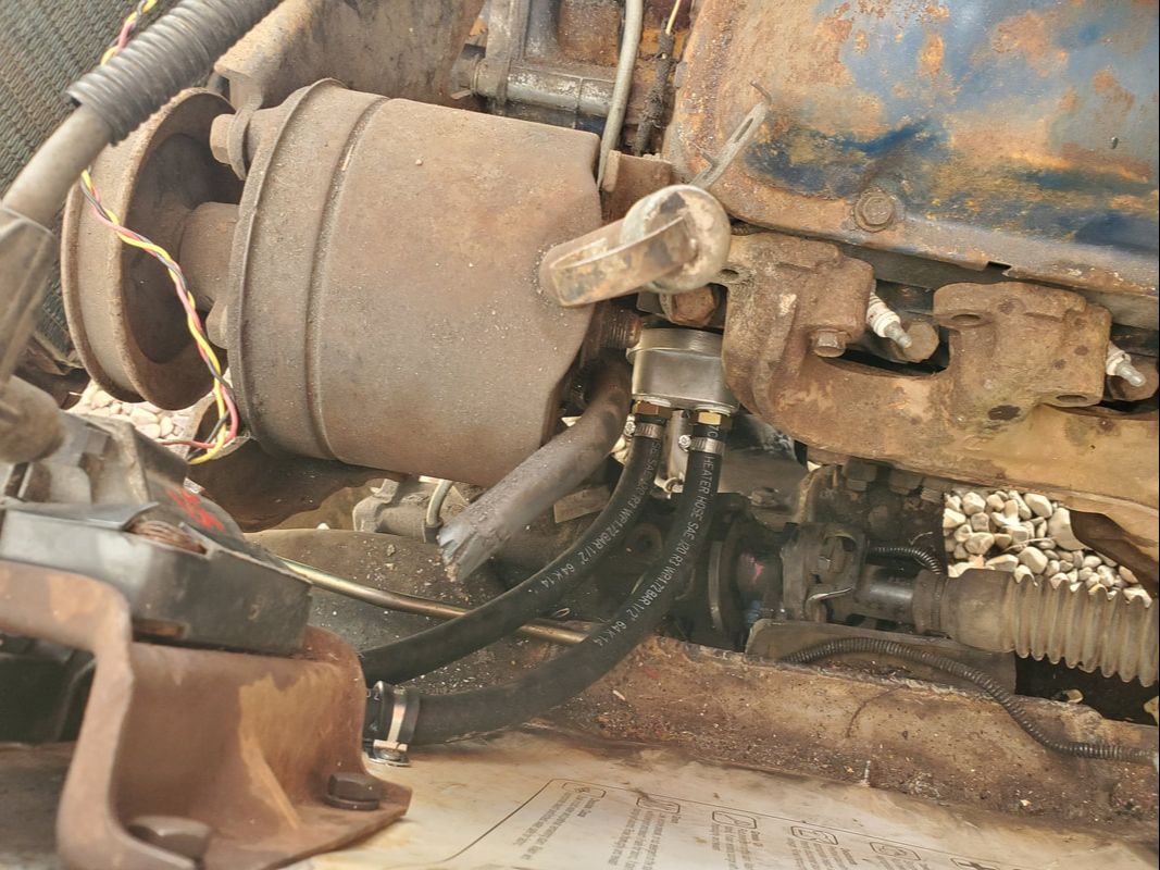
Engine block base of remote oil filter assembly mounted in place with hoses attached. Hoses are routed under power steering pump and are clear of any moving or hot parts.
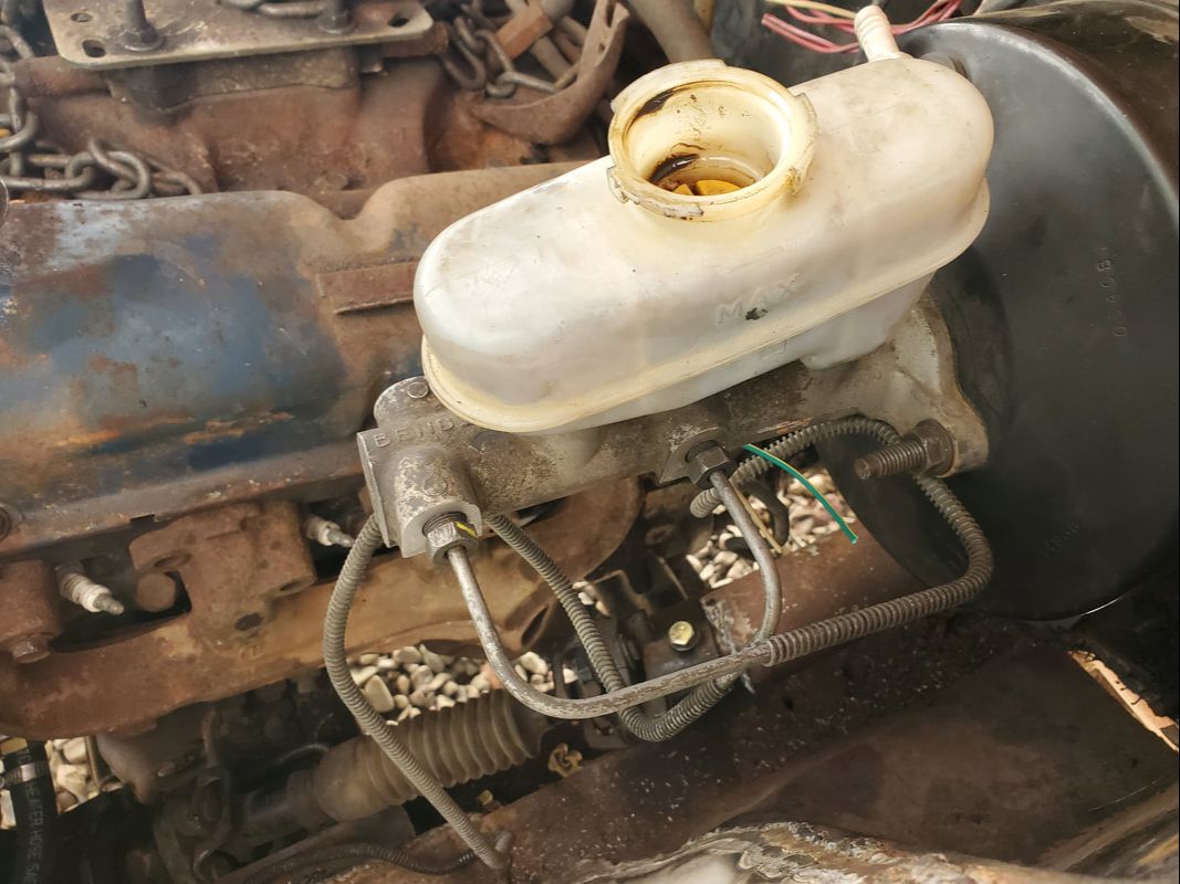
Brake master cylinder with both brake lines hooked up and cap off after filling reservoir up to see if system can move oil through the lines properly.
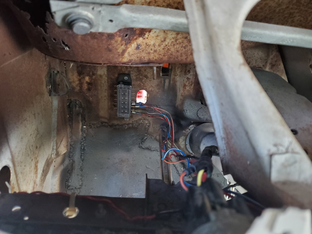
Fuse box mounted in place with some circuits already hooked up. Air vent box was removed due to being rusted and frozen. A cap plate will be attached to the opening later.
With the rewiring underway, I started mapping out the different circuits and running wires to their respective loads, taking time to zip tie everything to keep it all nice and neat. I took the time to maintain the same paths such as the door jamb channel or the same holes in the firewall to route the multiple wires that were used. I also took the time to use color coded and multi colored/striped wires based on the colors of wires on the loads. When necessary, I soldered extra wire to the ends of wires that were too short and used heat shrink tubing to cover the joints in order to create wire runs that were long enough to reach their loads. Another cool thing I managed to do with regard to the headlight and ignition switches, both of which were replaced with aftermarket switches, was modify the caps with the lettering etched on the surfaces to identify the switches. This way the interior looks pretty stock, even though the switches are not standard equipment. Under the dash the wire bundles were zip tied along the same paths, keeping the wiring as neat as possible, even as the numbers of wires add up. As parts came in the mail, I was able to complete many circuits. The radiator fan, fuel pump, radio, turn signal, all were completed. After getting most of everything wired up I was able to start testing the circuits. I did weld up a battery tray to replace the nonexistent tray. I tested everything with only a few hiccups in the turn signal system. Once those were ironed out and everything tested successfully across the board, I was able to move on and test fit the rear seat/interior components. I was able to mount everything except the seat bottom successfully. Its fine, the interior looks almost factory, except for if one would try to open the rear seat.
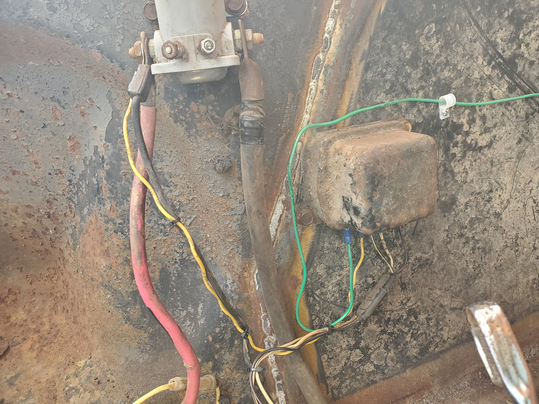
Voltage regulator and starter solenoid wired up after getting the schematics for the VR. At some point I'll upgrade to a 3G alternator with internal regulator, doing away with all this.
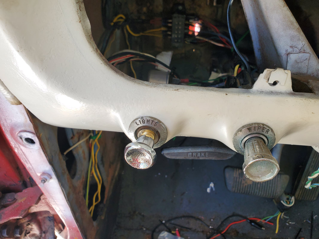
Headlight switch and wiper switch. Even though the stock lettered cap is in place, it has a universal switch installed in place, to the untrained eye this would look factory. Note all the wires strung around under the dash.
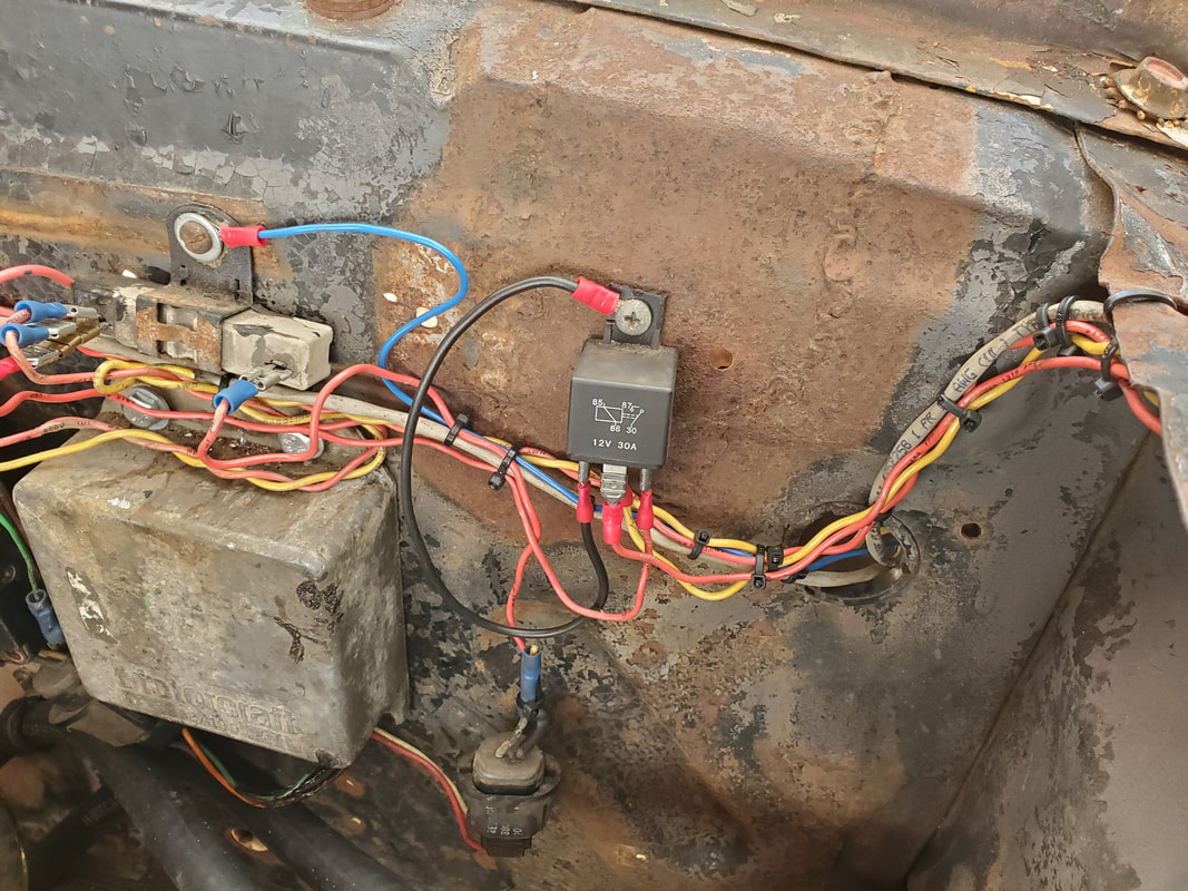
The Duraspark ignition system wired up with Chrysler ballast resistor. Automotive relay is for the radiator fan as that is a high wattage load. The wire bundle that is routed across the side panel feeds the circuit for the rad fan, headlights, and turn signals.
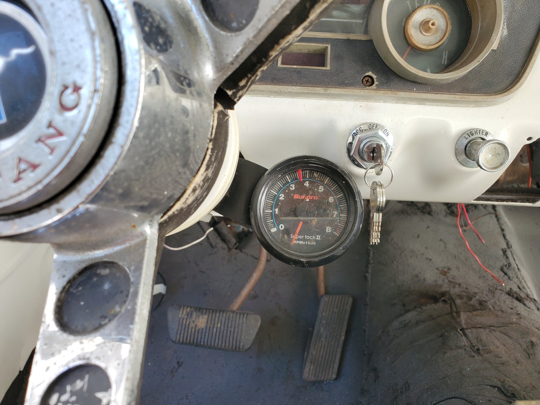
Tachometer installed with a large zip tie and wired in place. Note the ignition key switch, also with a lettered cap behind it.
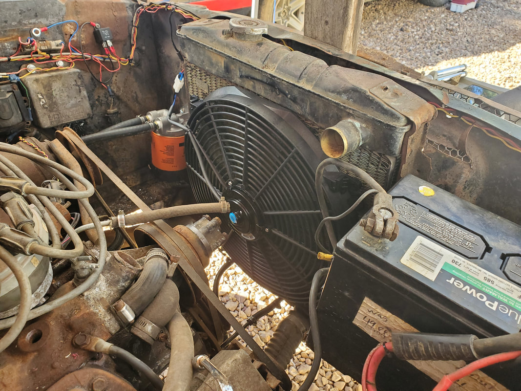
16" radiator fan mounted in place on the small radiator. This fan is large enough to cover 80% of the surface, negating the need for a shroud panel. The belt driven fan has been removed due to its interference with the top rad hose, which isn't installed but was eyeballed to verify this issue. Also note the battery being used for test purposes, setting on the welded up battery tray that was made from scrap.
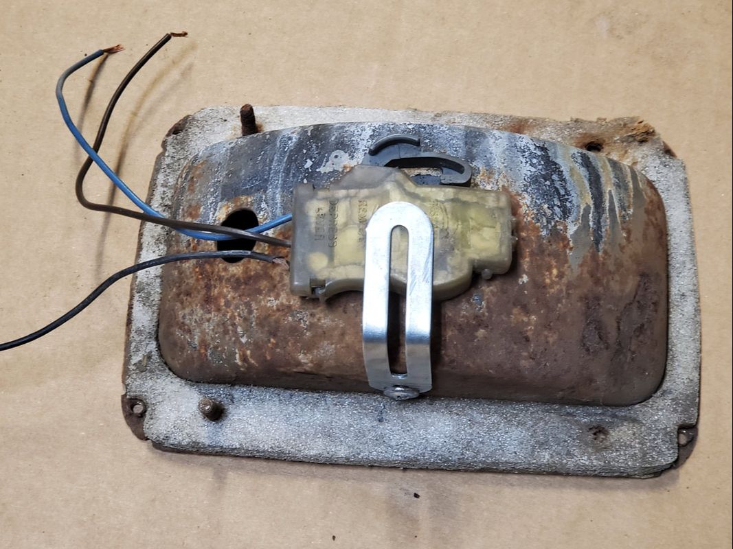
One of the taillights were too rusty to work. The old light socket was cut out and the hole trimmed to accommodate a light socket from another vehicle. A metal bracket was bent and used with a sheet metal screw to hold the light socket in place.
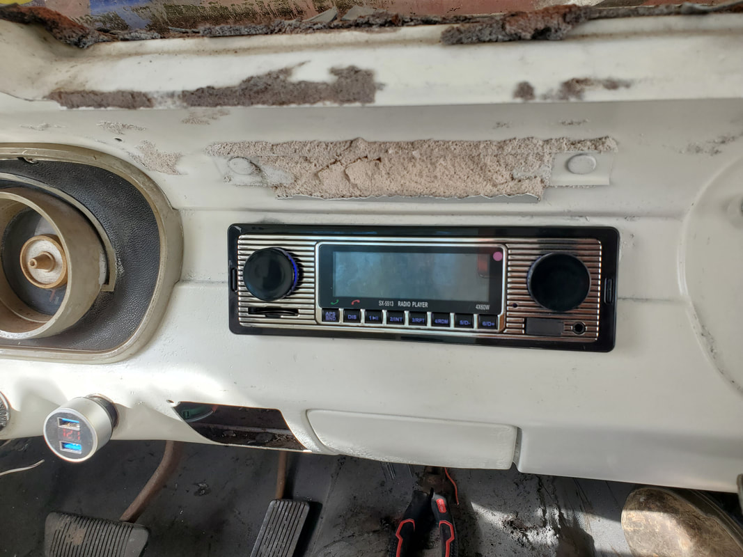
The retro style media player radio installed in the dash. This radio is bluetooth enabled so one's phone can be used as a receiver, played through the radio. Also note the USB charger plugged into the cigarette lighter socket, which also has a voltmeter to register the voltage of the electrical system, in the absence of an ammeter or dash mounted voltmeter.
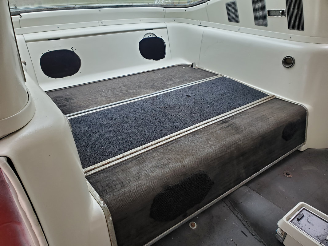
The rear seat body components mounted in place in the rear, giving the illusion of a factory rear seat interior. Just don't try to open the assembly to sit down, there's no seat base present.
The next thing that I took care of on the car was the installation of exhaust manifold gaskets. Even though the exhaust system was complete, I still didn't have the gaskets on. With a pair of gaskets in hand, and a bunch of bolts to secure the manifolds, I was able to finish the exhaust system in its entirety. The next thing was the fuel system. I already had the fuel pump in place but I still needed the fuel lines, tank and carburetor. I couldn't use the stock fuel tank due to its width being far too wide to fit between the truck frame rails. To remedy this, other than a fuel cell, the only option is a boat fuel tank. A 12 gallon boat fuel tank will be had, along with the metal to mount the unit in place. I also will have to add a fuel sending unit for a universal fuel gauge, which would be mounted under the dash as in the other vehicles with universal gauges. For now I just installed the fuel lines, two 6ft lengths, one on either side of the fuel pump. Straps using a nut and bolt hold the tubes in place through holes in the frame and a couple holes drilled through one of the frame mounts and the shock tower panel. On the back end I also drilled a couple holes through the truck frame body mount to hold it in place. Where the tubing passes through the frame at the rear going through the trunk and through the shock tower panel to the engine bay I used lengthwise cut pieces of rubber hose wrapped around the metal tube and pressed through the holes to serve as a cushion for the tubing.
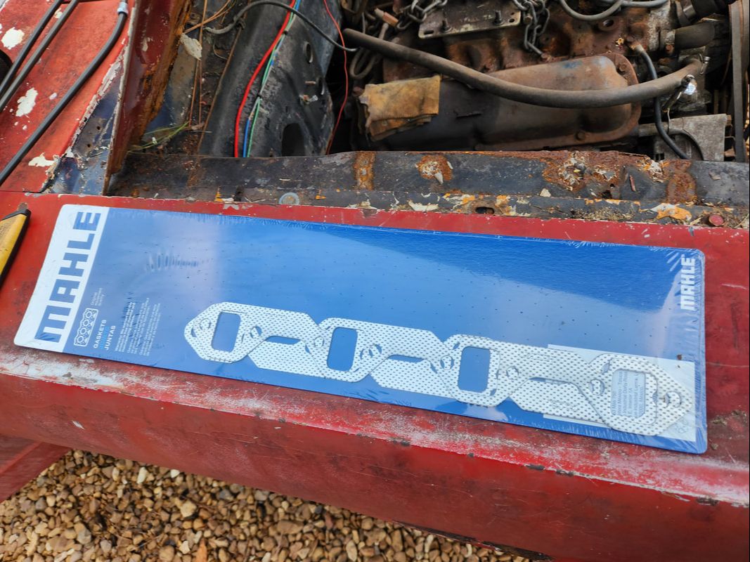
Pair of new exhaust manifold gaskets ready for installation.
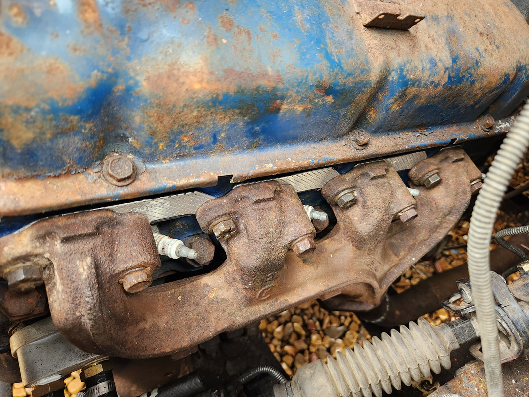
After gathering enough bolts to cover both exhaust manifolds, the gaskets are installed, completing the exhaust system.
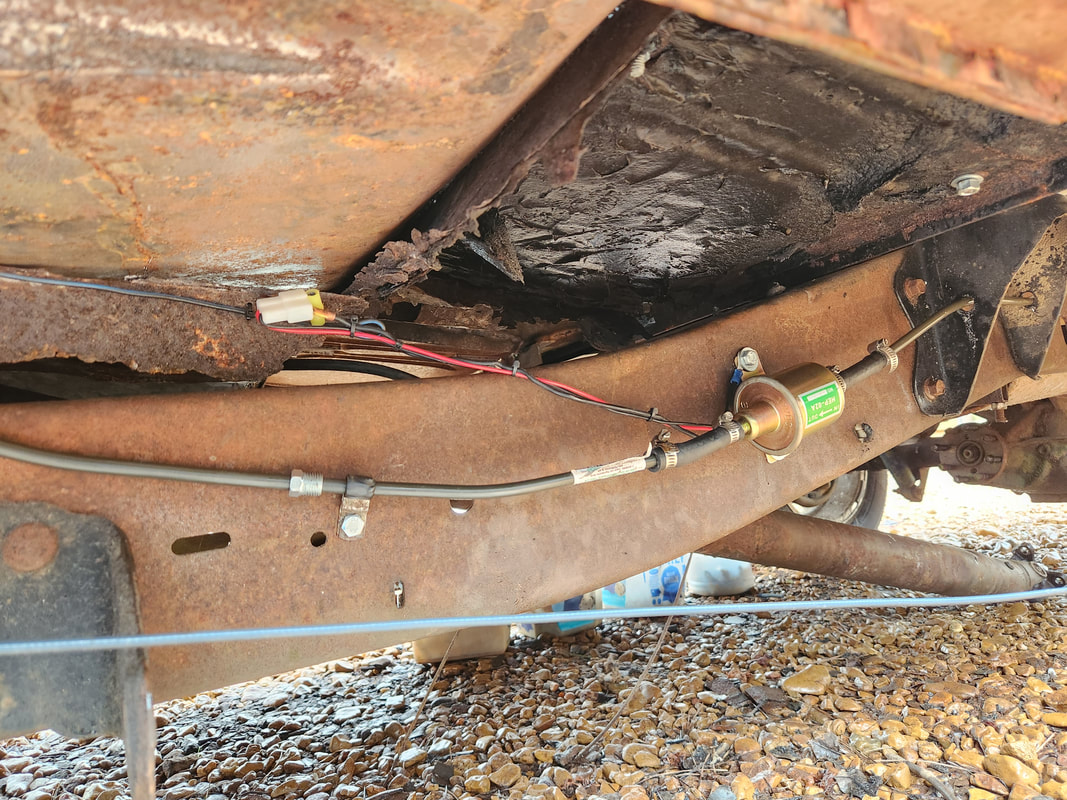
The fuel pump, centrally located, has a single 6ft metal fuel line attached on either side with a short length of rubber hose. The front tube is attached with a strap to a factory hole in the frame, using a nut and bolt.
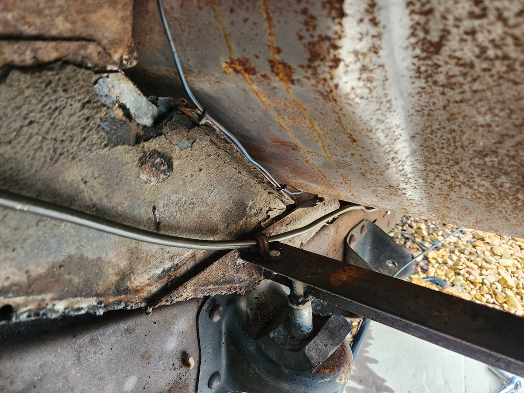
The tube is bent to go upwards at an angle following the old subframe, with another strap attached via nut and bolt to a hole drilled in the piece of angle iron frame/body mount.
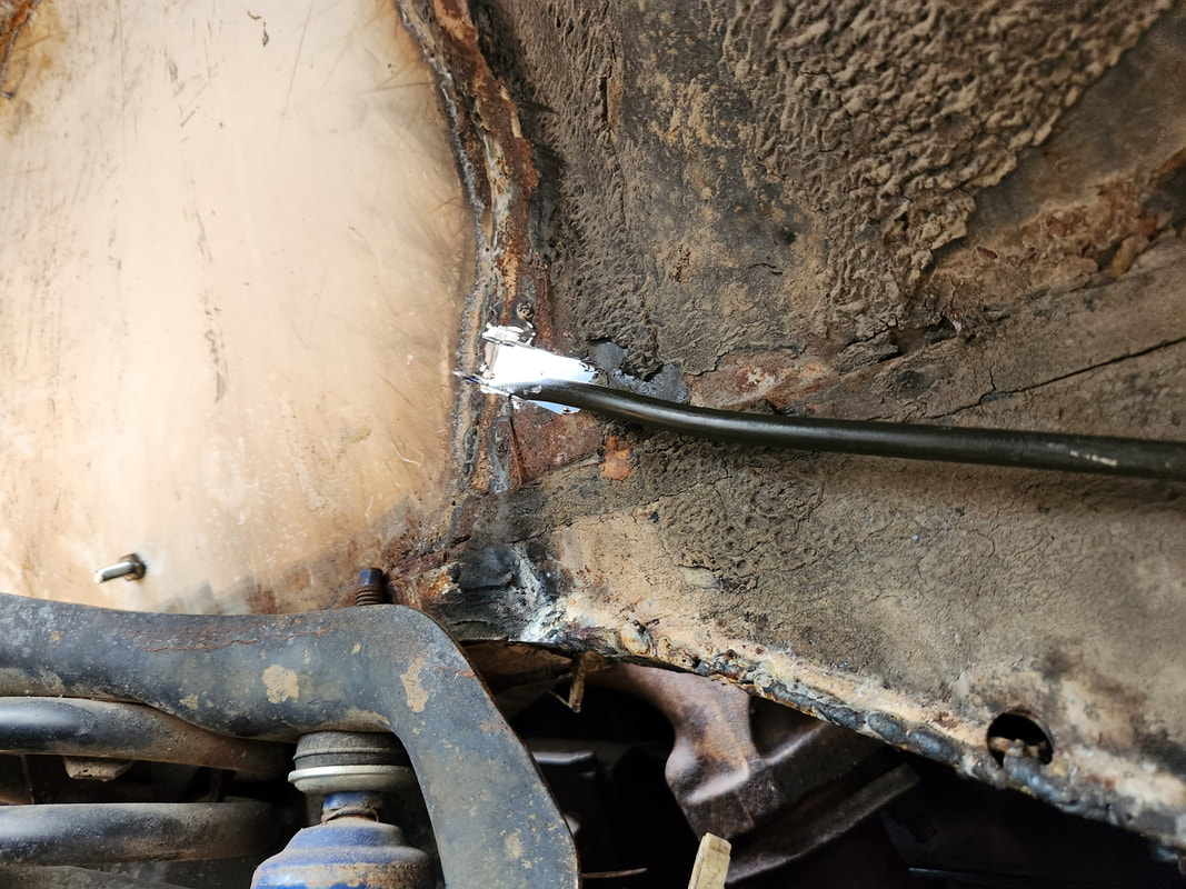
The tube is bent at a slight angle and routed through a large hole in the shock tower panel. Later a piece of rubber hose will be cut lengthwise and wrapped around the tube then pressed through the hole, providing a cushion between the metal tube and the edges of the hole in the panel.
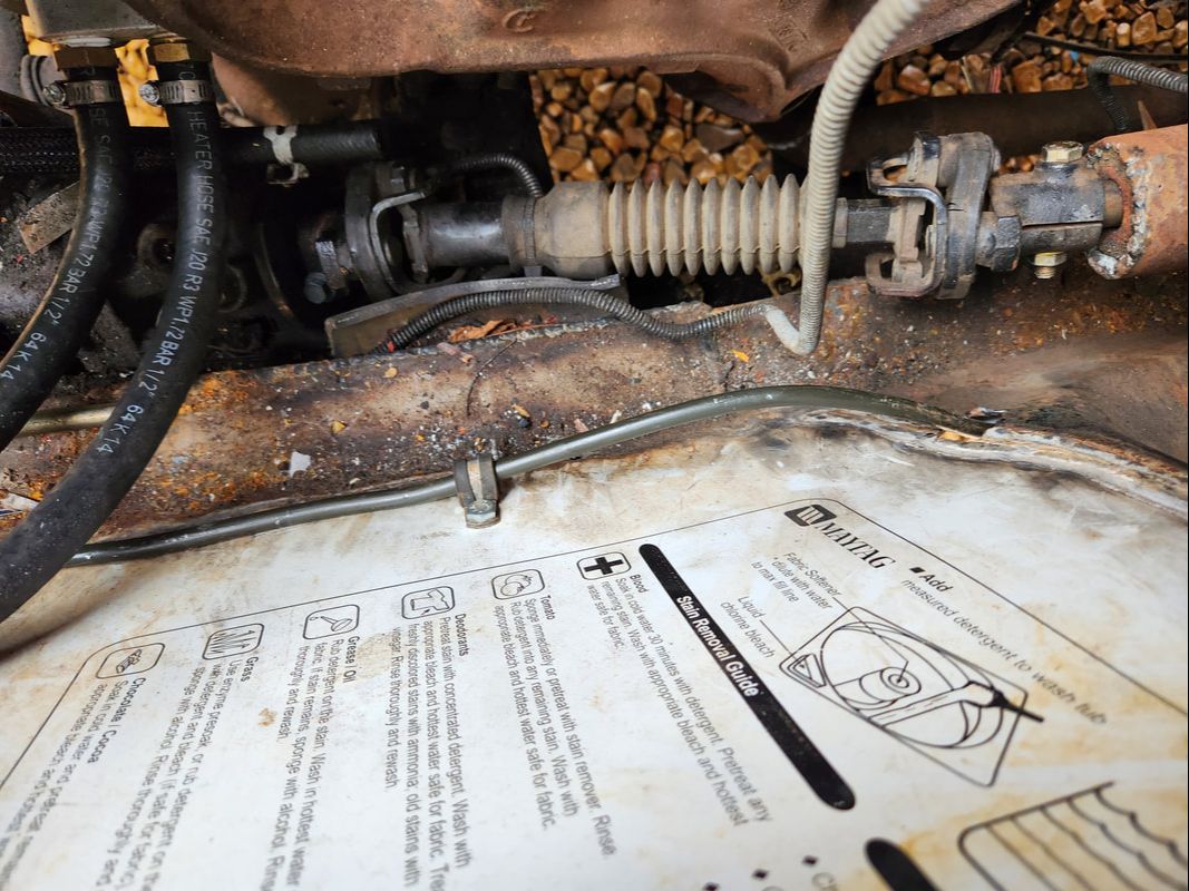
After passing through the shock tower panel, the tube is bent to follow right next to the inside of the panel up to where the power steering pump is. The tube is bent at a 90 degree angle to just under the PS pump.
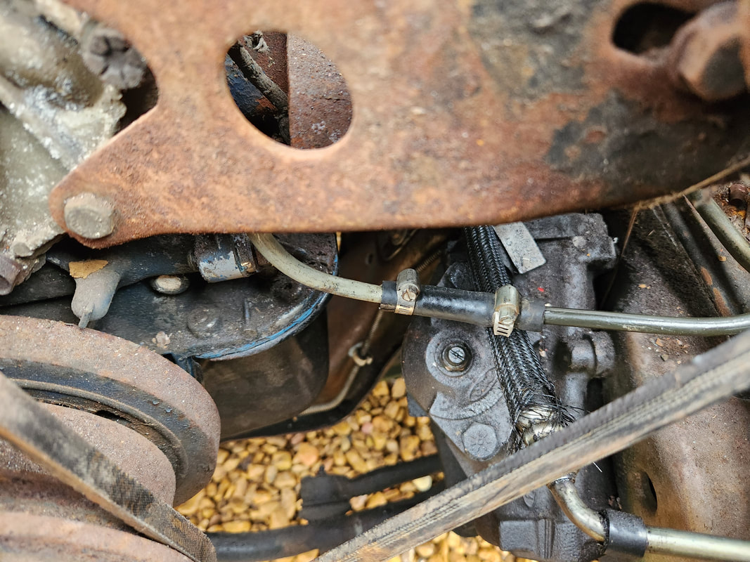
Under the PS pump the metal tube is connected to a short piece of bent tubing that continues up between the accessory brackets to the top of the engine where it bends backward toward the carburetor. A short piece of rubber hose connects the two metal tubes.
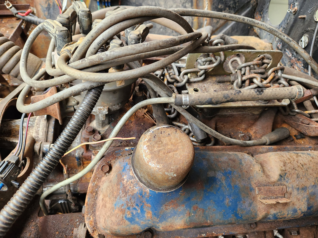
The short piece of bent metal tube which was originally on this car and connected to the mechanical fuel pump just under the PS pump, is routed up to where the carburetor will go.
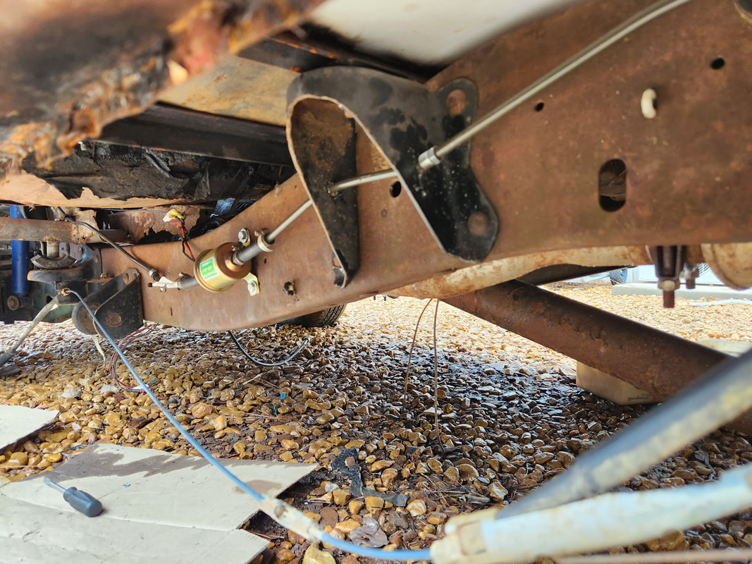
On the input side of the fuel pump the other piece of 6ft tubing is connected with a short piece of hose. A couple holes are drilled through the frame body mount to allow for the tube to pass through as part of the support of said tube.
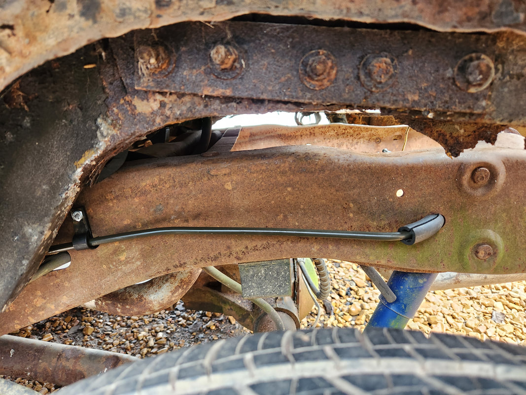
A single strap is used to hold the tube with nut and bolt through a factory frame hole. The tube bends to about 90 degrees through another frame hole, with a piece of rubber hose wrapped around the tube and passed through the hole to cushion the tube.
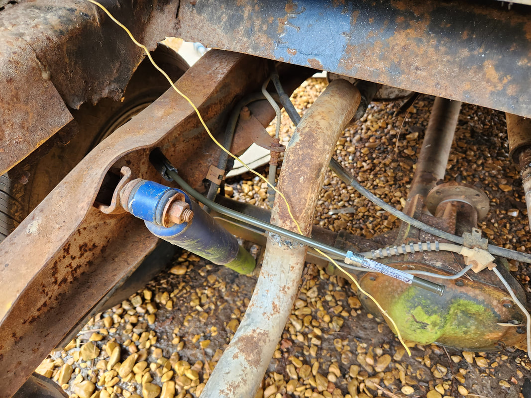
The last foot or so of tube is pointing straight into the trunk area where the boat fuel tank will be mounted. The end of the tube is at a point that should allow for a connection to the tank with a short piece of rubber hose.
After taking a brief break from the project yet again, I had an idea on how to address the fuel tank issue. I had an image of the old fuel tank from the Chevy LUV pop up in my head and with the image in my mind, was able to come to the conclusion that this fuel tank may very well fit the application. After doing a preliminary test fit of the tank, I found the tank would indeed work almost perfectly. Some extra metal on the truck frame rails would need to be trimmed off to widen the space between the rails. This would allow the tank to fit between the frame rails with no interference. I'll have to drill holes on the frame rails to bolt the tank down directly, eliminating my having to make a frame to support the fuel tank. The filler port end on the fuel tank is off center as the tank would sit, so I also had to figure out what to do with the filler tube on the taillight panel. I turned the tube 90 degrees to determine if the bolt holes on the panel would still fit, which they did. I did have to trim metal from the panel support frame/bracket, which holds the loop for the trunk latch mechanism, so the filler tube would be able to fit in the opening nicely without interference by the bracket. After fitting the tube I found that all I'll need is a short piece of rubber tube to link the filler tube ends perfectly. As for the rest of the trunk floor, I come to the determination that I would weld in some conduit tubes forward and aft of the fuel tank, then weld in pieces of sheet metal to close in these spots around the fuel tank. All I'd have to do then is apply one more section of sheet metal that would fit over the top of the fuel tank, taking into account the filler tube. This would cover up the remaining openings in the trunk around the fuel tank, allowing me to be able to use the trunk in a somewhat normal capacity. I will have to remove the sending unit assembly and use a universal sending unit to go along with a universal fuel gauge to take care of that part of the problem and along with the virgin 2bbl carb, will complete the entire fuel system on the car.
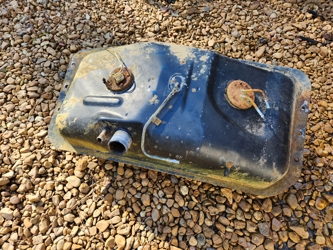
The old Chevy LUV fuel tank, which I still hung on to long after converting the truck to electric, must've been divine intervention that kept me from getting rid of this item.
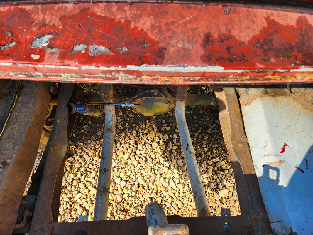
The space between the truck frame rails showing the curved areas that extend to the inside between the rails. These little wings of metal will need to be trimmed straight to allow the fuel tank to be able to rest between the frame rails without any interference.
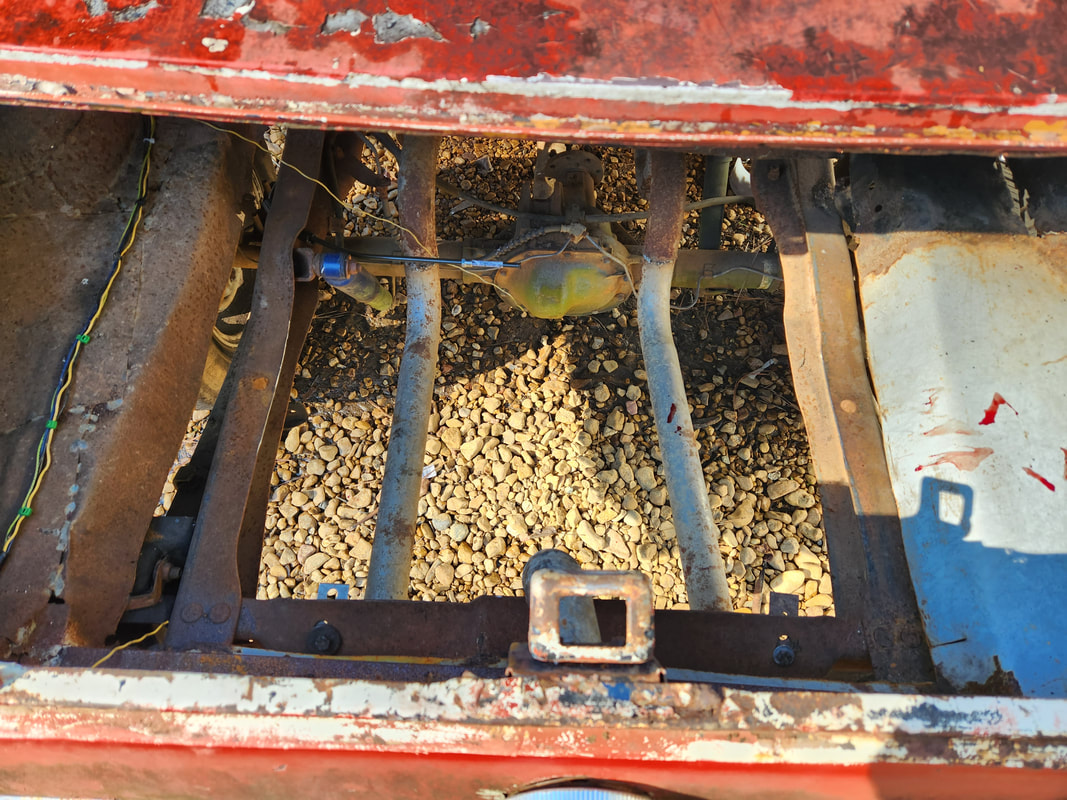
The frame rails after trimming down the extra metal.
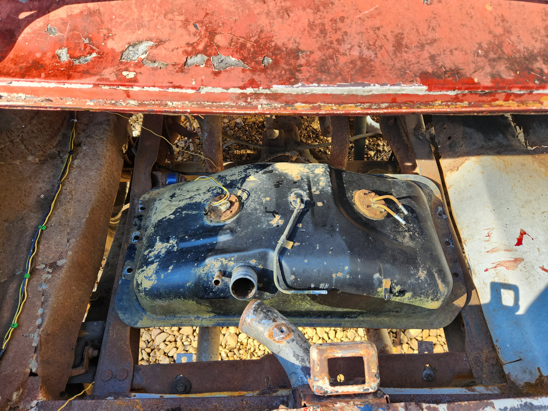
The fuel filler tube in its new orientation, showing how it lines up with the filler tube end on the fuel tank, only requiring a short piece of rubber tubing to couple the ends together.
Closeup showing the support bracket and where metal was cut away to provide clearance for the filler tube after turning it 90 degrees due left.
Metal tubes fitted fore and aft of the fuel tank to show their future placement and where sheet metal will be welded as permanent parts of the trunk floor. A removeable middle piece of sheet metal will go over the fuel tank to completely close in the trunk.
As is always the case with these one-off builds, the modifications that end up having to be done are unique, to say the least. After reorienting the filler tube, I had to cut new slits in the face to allow the fuel cap to sit with the logo horizontal. After clocking the filler tube 90 degrees to the left, it would've had the logo at a vertical position. Even after I cut the slits, I ended up having to weld in some slag and grind it flush to provide an anchor point for one of the latches on the fuel cap. To mount the LUV fuel tank on the Ranger frame in the trunk of the Mustang/Truckstang, I would do a setup where rubber heater hose is used as a cushion between the fuel tank and the frame rails. I cut a couple lengths of hose and split them lengthwise, then drilled holes in the hose to coincide with the holes on the frame rails. I placed the hoses around the frame rails, lining up the holes with one another. I applied bolts through the fuel tank and hose and frame rail, securing with washers and nuts. Once that was done, I had to pull the pickup unit and reorient that, so the nipples were facing forward instead of backward, as the tank sits in the trunk. I carefully twisted the pickup screen tube enough to reorient the pickup screen to sit in the cavity at the bottom of the tank when the pickup unit was clocked 180 degrees, placing the nipples forward. In this new position I was only able to use three out of five of the mounting screws due to the bolt pattern only allowing for a fit in one position. I'll probably have to use gasket maker to further seal the bushing on the pickup unit if this thing proves to be leaky later. Last thing is the filler tube. Since the angle between the ends of the filler necks was a sharp angle, the hose that normally goes with this car's filler tube would be unable to bend to that angle, so I cut the filler tube down, maintaining an angle that allowed me to fit an angled piece of exhaust pipe to the end of the Mustang filler tube, putting the end of the exhaust pipe at a lighter angle, almost straight in line with the filler neck on the fuel tank. The exhaust pipe and filler neck will be welded together, and a smaller diameter piece of rad hose will be able to be used to couple the filler necks, versus having to source a filler neck hose or a super large rad hose.
Filler tube bolted down after cutting notches and welding some extra metal in place to provide anchor point for latches on fuel cap.
Fuel cap applied to filler tube face after bolting tube down in the new orientation.
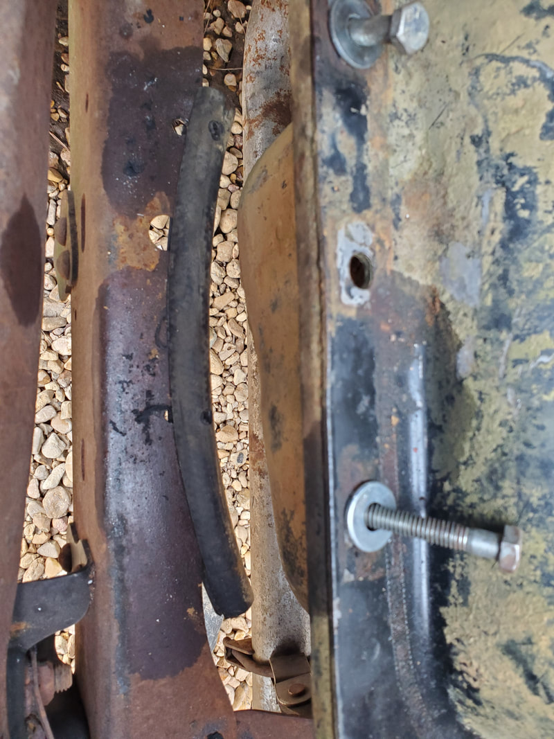
Heater hose that was cut lengthwise and drilled to fit the holes on the frame rail. Fuel tank will be set down over these hoses and bolts placed through to hold everything together.
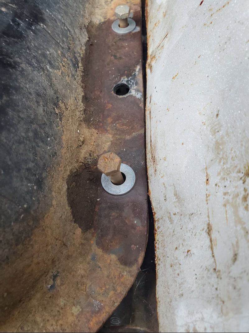
The fuel tank set down on the heater hose after making the cuts/holes and fitting the hose over the frame rail. A bolt is already applied through all the holes to help secure the tank.
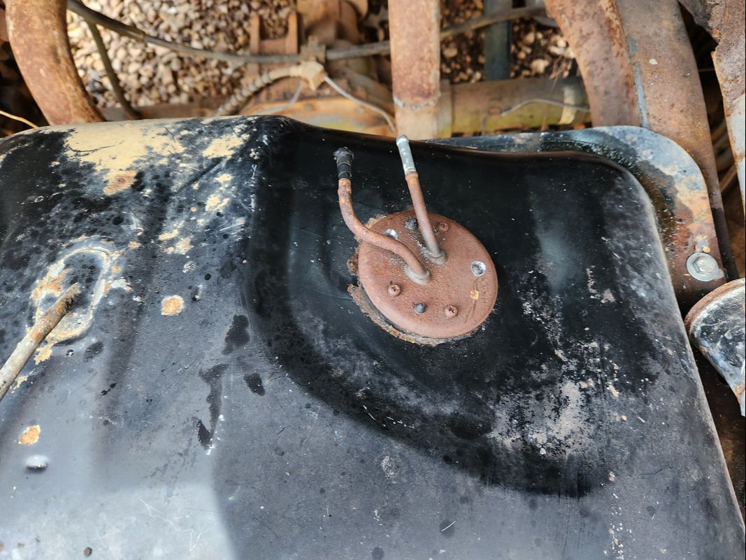
The pickup unit in its new orientation with the nipples facing forward instead of backward. The pickup screen has been twisted to allow it to fit in the cavity at the bottom of the fuel tank when the unit is in this position.
With the fuel tank in place, I had to figure out the filler tube situation. I ended up buying a length of rad hose just to cut a short length off for the filler neck coupling. Because of the weird shape of the filler tube, I wasn't able to put the hose on with the fuel tank stationary. Because I had initially welded a tube in front of the fuel tank in an attempt to start the front third of the trunk floor, I was unable to move the tank forward. I ended up cutting that tube out to allow me to move the fuel tank forward so I could install the hose between the filler necks, then bolt the tank back down, along with the filler neck in the taillight panel. After that was done, I fabricated a front third trunk floor panel from some shelving legs and sheet metal. This panel is a removable panel, secured by two studs made from two long bolts installed and welded in place in the fender wells at the back of the panel and with two lag bolts holding the front of the panel in to the rear panel separating the cab from the trunk. A rubber hose was cut lengthwise and slid over the rear leg to serve as a cushion as the panel was sitting on top of the fuel tank.
The next thing was the carburetor. I only had one base gasket but needed two, since the spacer needed to be added. I cut a spare gasket from some thick gasket paper stock to remedy that problem. Gasket maker helped seal everything. I also had to make a plug out of JB tank weld epoxy to fill an extra opening on the spacer that was not covered by the gasket or carb, since this spacer wasn't exactly matched to this carb. With the epoxy plug and gaskets made, everything was bolted down to seal up the whole fuel system from the carb down. On the fuel line, I had to reroute the line to the right side of the distributor since the input nipple is on the right side of the carb as it faces forward. I added an inline filter to the line as it goes into the carb for added protection. As for the throttle, I had to cut the loop end on the throttle lever on the car and weld it back in place, placing the loop at a lower level, placing it in line with the throttle lever on the carb. A scrap linkage made from an eyebolt and short piece of rod was welded to a short screw holding a throttle link end, which was snapped to the ball tip on the carb throttle lever. A 3/8" bolt and lock nut held the eyebolt to the loop on the throttle lever. This allowed the accelerator pedal to pivot the throttle lever enough to pull the carb throttle to wide open throttle. I added a spacer to the top of the carb for an air cleaner and also set the timing on the distributor so I could install the plug wires to the right points on the dizzy cap and plugs.
The short piece of rad hose cut from the new stock to accommodate the filler tube connection to the fuel tank filler neck.
The fuel tank secured with the filler tube hose connected in place between the tube ends.
The front third trunk floor panel made from shelf legs and scrap sheet metal.
The panel is secured to the trunk with two bolts welded in place at the rears of the fender wells to become studs. Nuts hold the rear of the panel to the studs. Lag bolts through the front portion of the panel and through holes in the divider panel hold the front in place.
A piece of heater hose cut lengthwise and fitted over the middle of the leg end on the panel provides cushioning for the panel against the top of the fuel tank. Two sheet metal screws hold the hose to the leg through drilled holes.
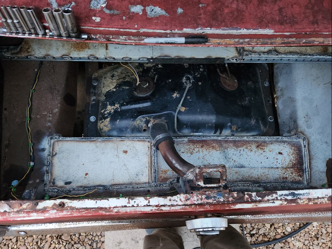
As an added bonus, the rear third of the trunk floor was completed by welding in a couple pieces of sheet metal to the open space where the tube was welded behind the fuel tank. I also cut the tube and rewelded it closer to the fuel tank since there was no need to have the spacing between it and the back of the fuel tank.
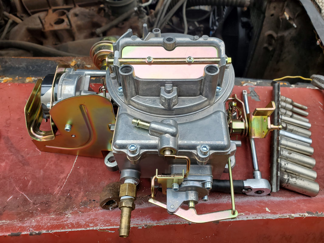
The faux 2100 2bbl carburetor, ready to go.
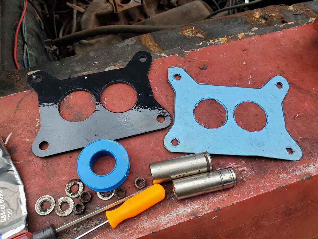
The black base gasket that came with the carb plus the extra one made by tracing the outline of the black gasket onto gasket paper and cutting it out.
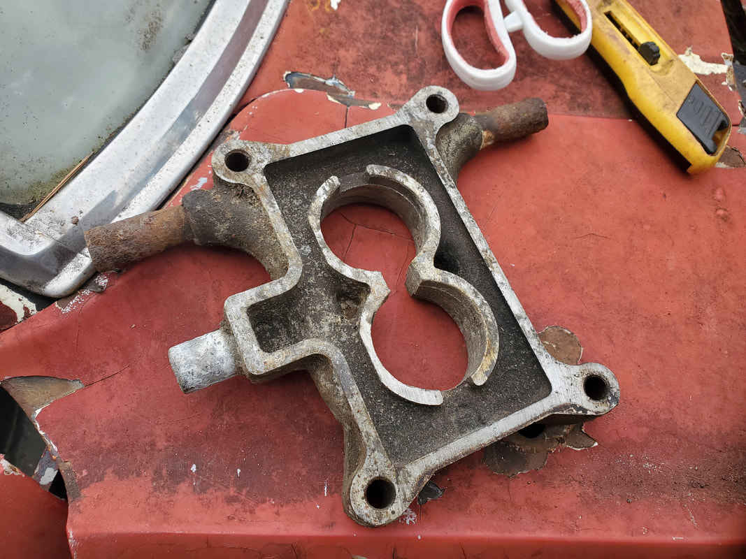
The spacer piece. Note the extra portion where the vacuum port is located, It should be straight from on end to the other. This extra portion needed to be plugged with epoxy in order to seal the open areas around the barrels from the outside.
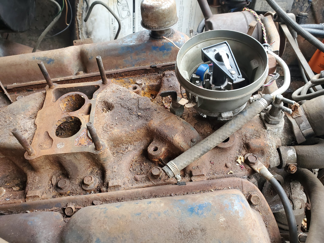
The base of the intake is cleaned off and ready for gasket maker and the gaskets, spacer and carb.
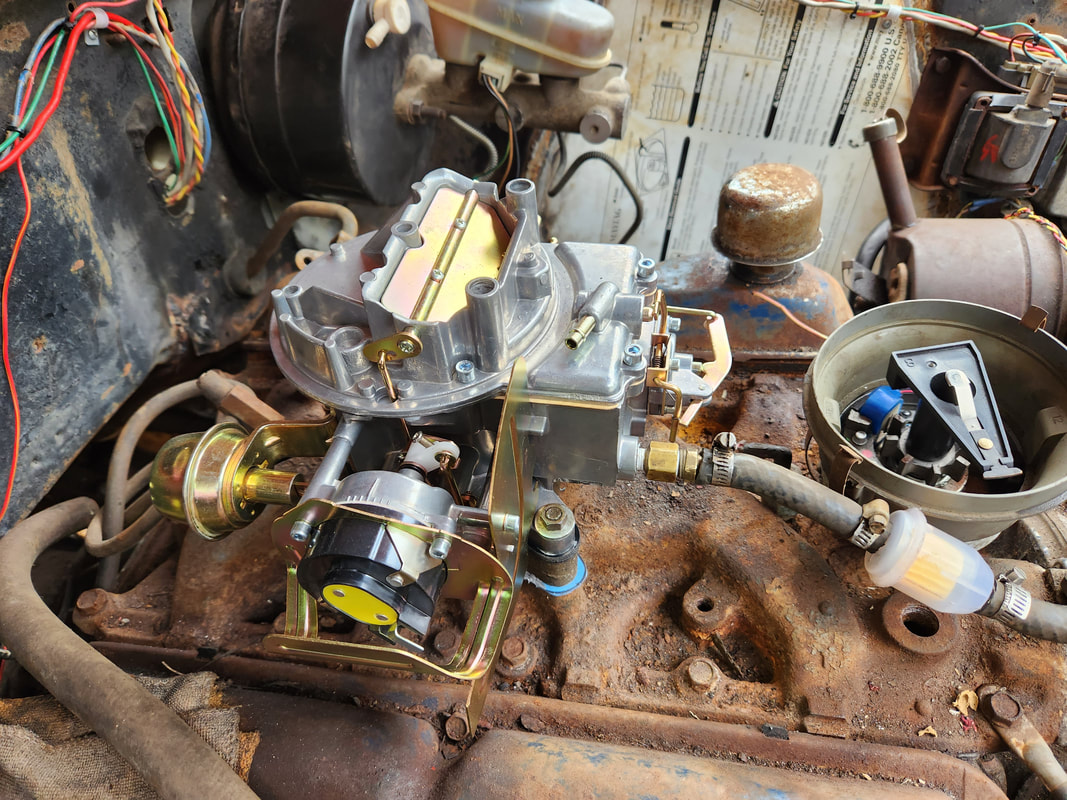
The carb is bolted down on top of the spacer and the gaskets, sandwiched between the intake and the spacer and carb. The epoxy plug was applied when it was soft and the gaskets and carb pressed down over the plug to mold it nicely against the spacer and bottom of the gasket/carb. Note the fuel line and inline filter routed around the right side of the distributor and connected to the nipple on the front right of the carburetor.
The eyebolt welded to a piece of rod along with the throttle link end and screw. The bracket was the old throttle cable bracket that was removed from the intake as it wasn't needed with our throttle lever.
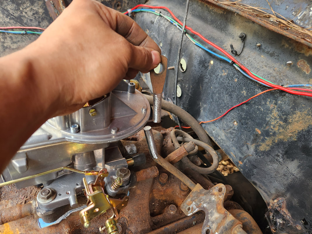
The loop end portion of the throttle lever cut free and both ends ground clean for welding.
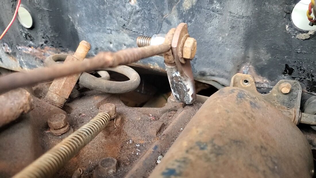
The loop end welded to the side of the lever and the eyebolt linkage bolted in place holding the eyebolt and loop end together. Note the return spring in place for the carburetor linkage.
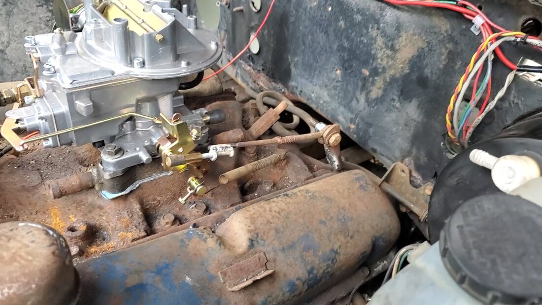
The overall throttle linkage, showing the welded screw at the front end of the linkage. The throttle linkage end is screwed in place and snapped over the ball tip on the carb throttle lever.
As an aside I moved left to take care of a couple little tasks that even though they're not pertinent to getting the car running, they were little things that would be nice to address now so they wouldn't be another thing later on that needs mopping up. One of these things was the addition of H4 headlight housings. I already wired the headlight circuit for the H4 LED bulbs, but without the housings, the bulbs were just dangling under the fenders. The whole job was easy, just removing the trim panels then the headlight rings, removing the old bulbs then doing everything in reverse with the addition of the H4 bulbs. Another little thing I had to address was the sending unit on the fuel tank. Since the arm on the unit was opposite the end I needed it to be for the gauge to read empty when the tank's empty, I found that it would be possible to change this by turning the sending unit around to allow the arm to swing to the side I need it to be. I had to bend the arm to allow the float to freely move in the new position and not hit the side of the fuel tank. After testing the movement of the sending unit arm in the new position, I applied gasket maker to the rubber gasket since I was only able to apply two out of five screws to hold the unit in place. With this done, after taking a little trip to the junkyard and grabbing some useable items, one of which was a PCV valve for a SBF V8, I installed the piece along with a length of hose to the nipple on the rear of the carb. While I was at it I added another length of hose to the power brake booster, connecting it to the large nipple on the vacuum line manifold fitting that is at the rear of the intake. The last thing that I did was install a 2" universal gauge bracket, also sourced from the junkyard. The fuel gauge I installed was dangling free and needed to be mounted to a bracket, so my finding this triple gauge bracket was convenient. Even though its just one gauge, I do still need to get an oil pressure gauge, and since its a three gauge bracket, I figured I can get a voltmeter to fill that spot. Since the only voltmeter in the car is a little USB charger that plugs into the cigarette lighter socket and has a meter to show voltage at the socket, a voltmeter was a logical choice. If I had an air/fuel gauge or boost gauge for a turbo, then either of those gauges would be a logical choice, but we're going with a voltmeter. In the meantime, I just installed the bracket with the fuel gauge in the center, completing that one install with the addition of the bracket. The last thing was the addition of a battery, courtesy of the junkyard. When I made the battery tray, I miscalculated the position of the regular class 24 battery I typically use so to remedy that problem I had to use a GM side post battery along with screw in battery lugs. This battery sits in the tray nicely and the positive terminal is opposite the side wall.
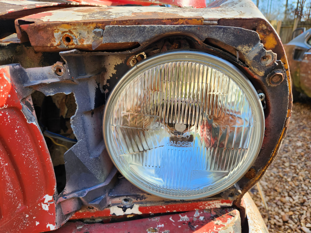
H4 headlight housing in place with ring secured. With the current LED bulbs, I'll have to come up with some way to cover the rear of the bulbs so water on the road won't be splashed onto the back of the bulb. Other styles of LED bulbs are lower profile, allowing me to apply the rubber sealing cap that would normally be added to halogen bulbs.
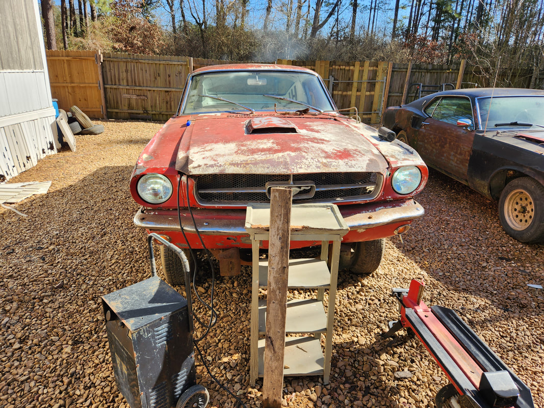
The LED headlights are on after the installation. Note the trim panels are back in place. The left LED bulb is not as bright as the right but both units are on.

The sending unit with the arm after bending it to allow for free movement in the new position. I had to clock the unit to allow the arm to swing to the opposite side of its empty resting position so the fuel gauge would read empty instead of full when the tank is actually empty.
The PCV valve and hose hooked up along with the brake booster hose. With these hoses in place, the overall fuel system is complete, save a threaded rod and wing nut for the air cleaner. Note the spacer added to the top of the carburetor.
The three gauge bracket mounted in place under the dash after drilling a couple holes to secure the unit. The fuel gauge is secured in the middle hole on the bracket.
The side post battery resting nicely in the battery tray with cables permanently connected. Note the positive terminal/cable is opposite the side wall so it's safe from shorting.
A new thing that I decided to attempt was the "making" of a driveshaft for the car. The shaft that I picked up from the junkyard is a bit too long and would need to be shortened, but there's a process to doing this correctly. First thing is carefully grinding through the weld bead to free up one of the yoke bases, in our case the rear yoke. Once the weld is ground away, the yoke can be tapped out. Next measurements have to be taken to determine how much tube to cut off. This was done by putting the front yoke into the transmission, bolting the rear yoke in place then lining up the tube end to the yoke and seeing what the overhang is and marking it accordingly for cutting. The cutting was done on a bandsaw to ensure an even cut, using a level to ensure the shaft and the saw body were both even for the cutting. Once the tube was cut down, the yoke base had to be put back into the tube. To do this, phasing had to be adhered to, which is ensuring the U-joint caps are lined up on both the front and rear yoke bases. I will say that I did this with the level as a straight edge, which wasn't the most accurate method but enough to hopefully have the phasing as close as possible. Next, I had use a dial indicator to check the shaft runout, which is the amount of wobble or drifting from dead center the shaft does as it's rotated. Once this was done the yoke base was tack welded, then checked again for a runout within tolerance before being removed and fully welded. After the welding was donem the bead was ground even and smooth all the way around. This is to ensure an even amount of metal all around to hopefully maintain balance on the shaft. The next move will be balancing the shaft, which will have to be done when the car is running, as the rear wheels will have to be off the ground and the driveline engaged. While the driveshaft is rotating under power, a piece of chalk or something similar is brought close to the shaft, and as the shaft wobbles from imbalance, the tube will bounce out and hit the chalk, leaving a small mark. This is done at the front and back of the shaft tube. Afterward, hose clamps are added at the front and back of the shaft tube, with the clamp body placed opposite the chalk marks. The driveline is rotated under power again and checked for balance, with the clamps moved slightly and run again, and again, until hopefully the shaft is balanced.
The rear yoke of the driveshaft after grinding weld bead and tapping out the base from the tube. The rear was done instead of the front as a safety thing and because it would be easier to apply the dial indicator at this point. If the weld was compromised, its better to be at the rear so the broken shaft doesn't dig in the ground and pole vault the car, a rear yoke failure at worst will ruin the transmission.
The rear yoke is bolted to the rear end and the shaft installed in the transmission, being lined up for measurement in order to cut the tube down.
After tube was cut down on the bandsaw, the yoke was phased with the front yoke and tapped back in. The shaft was installed and the dial indicator set up, using the magnetic base, bought with the gauge itself, hung on the rear end body. As the shaft is rotated, and the sway of the shaft presses against the dial indicator plunger, I tapped the shaft tube to try and straighten out the yoke to make it truer so the runout number on the indicator, based on the amount of swing goes down. Tolerance or variation is 0.012", max is around 0.015".
After runout is corrected, the yoke was tack welded at four spots, then checked again to make sure no changes occurred. The shaft was then removed for final welding.
The final welding was done with a more powerful welder all the way around the yoke, then ground down to even out the weld bead to hopefully maintain some level of balance. Too much metal at any one point can throw the shaft off balance.
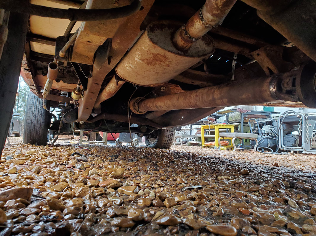
The shaft is reinstalled on the car, ready for the balancing phase of the project.
With the driveshaft in, I ordered the remaining gauges I needed to fill the slots in the gauge mount under the dash. The oil pressure and volt gauges were what I planned on using, so I can read oil pressure as well as be able to remove the USB charger dongle from the 12v receptacle, which happened to have a built-in voltmeter. The sending unit on the oil pressure gauge was too wide to use so I had to use the stock unit with a resistor in series to hopefully allow the circuit to read somewhat close to accurate, or at least be able to show me a range of values that would indicate that the engine is producing oil pressure. I also had to install a speedometer cable to plug the hole on the side of the transmission so I can fill it with oil as well as complete that little bit of work on the build. With the gauges and cable in and hooked up, I was able to attempt a startup. I had already added over 5 gallons of fuel, so I was more than able to run the engine. Unfortunately, the first attempt was met with failure. The battery appeared to not have the juice to crank the starter, despite the load tester I used on the battery showing that it was in decent shape. I swapped out the starter with another unit I had in our inventory and tried again, with the same failed results. I fumbled around with the distributor, retiming the thing several times, clocking the distributor and wires, and even with all this, still no go. I had to troubleshoot the ignition system and found the module wasn't putting out, so I swapped that out. I was able to get spark for a moment but then lost it again, so I don't know if the module crapped out or if system voltage is making the module not work. When the ignition system had power, the voltage dropped from 12.1 to 11.5 give or take. Still not too low as far as cutting off the ignition system so it's become a puzzling and aggravating issue. I ended up swapping the starter out yet again due to the apparent weakness of the cranking of the engine with still the same failed results. The only other thing I can figure is the idea that the engine is still super tight due to it being a rebuilt engine that was never broken in and sat for over 15 years to boot. I may very well end up having to add a high torque racing starter and the highest cranking amp battery I can fit in the tray to give me the cranking ability I need to spin this tight engine around. I also want to swap over to a GM style HEI dizzy and remove all the cluttered Duraspark garbage, which will neaten up the engine bay and eliminate the problematic ignition system which was full of old components and multiple connections that were questionable at best. The closer I get to getting this car running the farther it seems I get pushed back, but we'll get there.
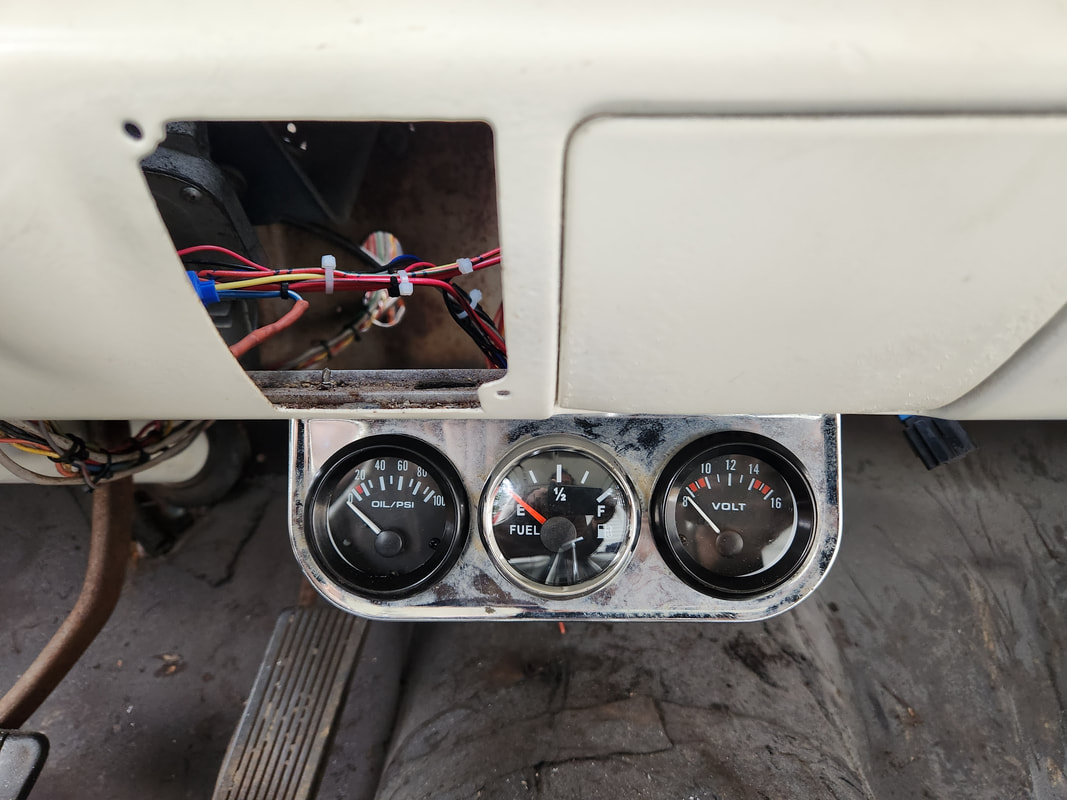
All three gauges installed on the gauge panel, volt gauge, oil pressure and fuel gauges.
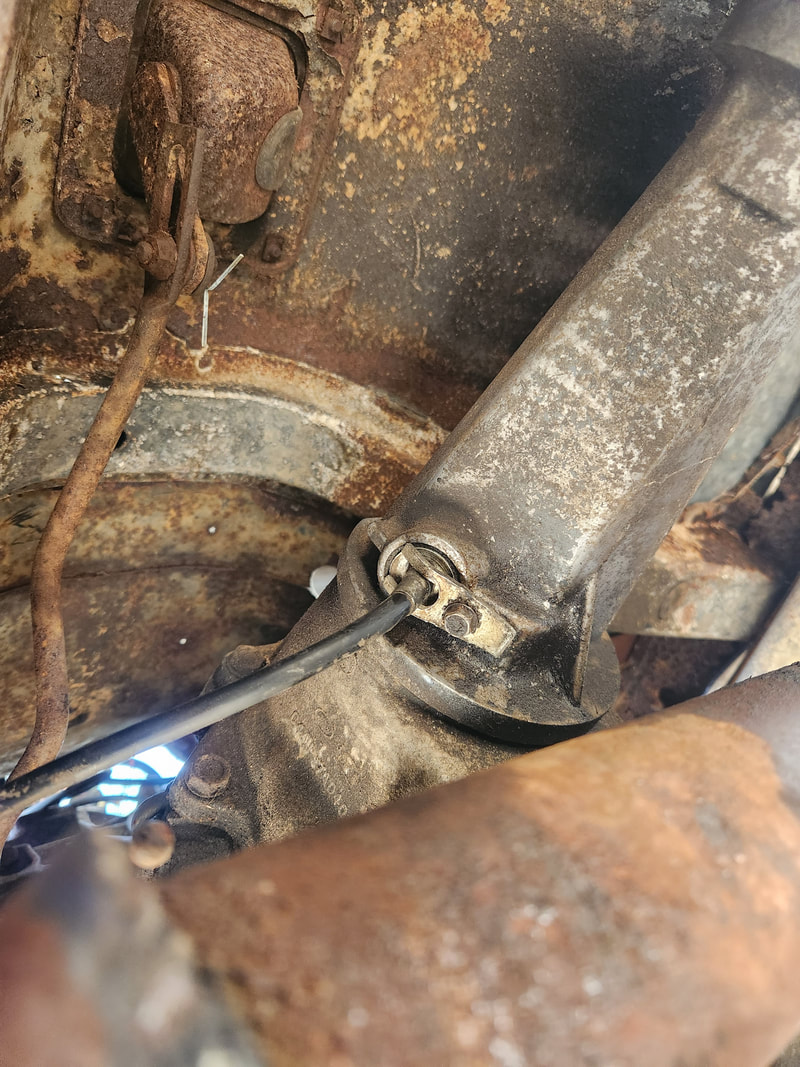
The tail shaft of the transmission with the speedometer cable installed.
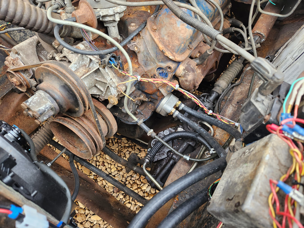
Another little thing I took a moment to do was remove the power steering pump and bracket from the engine. Since there's no hoses hooked up, the pump will just spin dry until it destroys itself so it makes sense to get it out of the way. If the vehicle proves to be controllable w/o the pump, I'll rig up a bypass hose for the steering gearbox and just roll with that setup, sans PS pump.
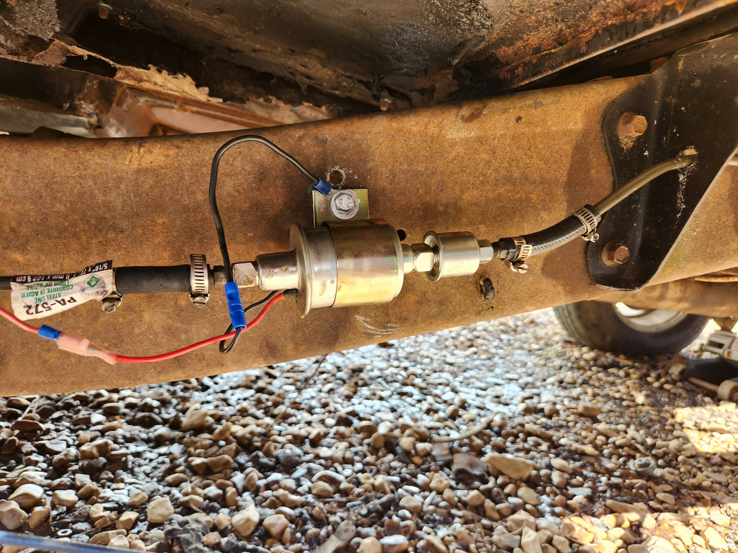
Before attempting to start the engine, I had to make sure the carburetor would get fuel. It appeared the old pump didn't have the ability to pull fuel from the tank and push it up to the carburetor unless it was right on top of the fuel source. This pump with the integrated filter was removed from the Dodge as it didn't need it at the time. This pump is more than capable of pulling fuel from a long distance and still pump enough volume to the engine.
During several failed attempts to start the engine, I changed the starter solenoid, as the old unit started smoking during the longer duty cycles the starter was going through. Still didn't help though.
I changed the original starter as it was old, probably between 15 and 20 years old. Even after changing out from this one, the other starter still didn't appear to have the pull to crank the engine. A third starter was swapped out later with the same results.
I ended up removing the side post battery I had neatly tucked in the battery tray for the larger battery that was in the FMT. This battery was thought to be bad but apparently wasn't, it just didn't have the CCA to crank the starter against this tight engine for too long.
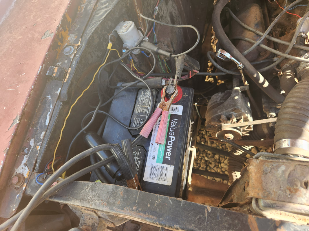
The slightly larger battery from the FMT installed side ways so it can sit in a position that keeps the posts from touching the side panels while still being away from the engine. I'll have to possibly source another side post or other battery that allows the posts to be in positions that put them safely away from the sides while still being able to sit in the battery tray nicely.
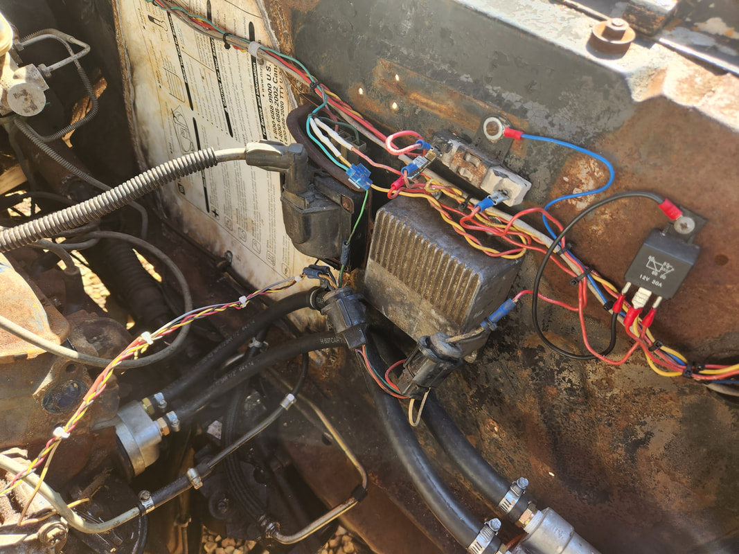
After swapping out the ignition module once, then losing spark once again, it was decided that this old Duraspark system, complete with all its old components, most of which were salvaged from junkyard cars 20 years ago, would be replaced with a newer GM style HEI distributor that puts everything within the distributor and cap unit, making for a neater installation, only requiring one power wire to operate, and an additional wire for a tach, if installed. All this clutter will be a thing of the past.
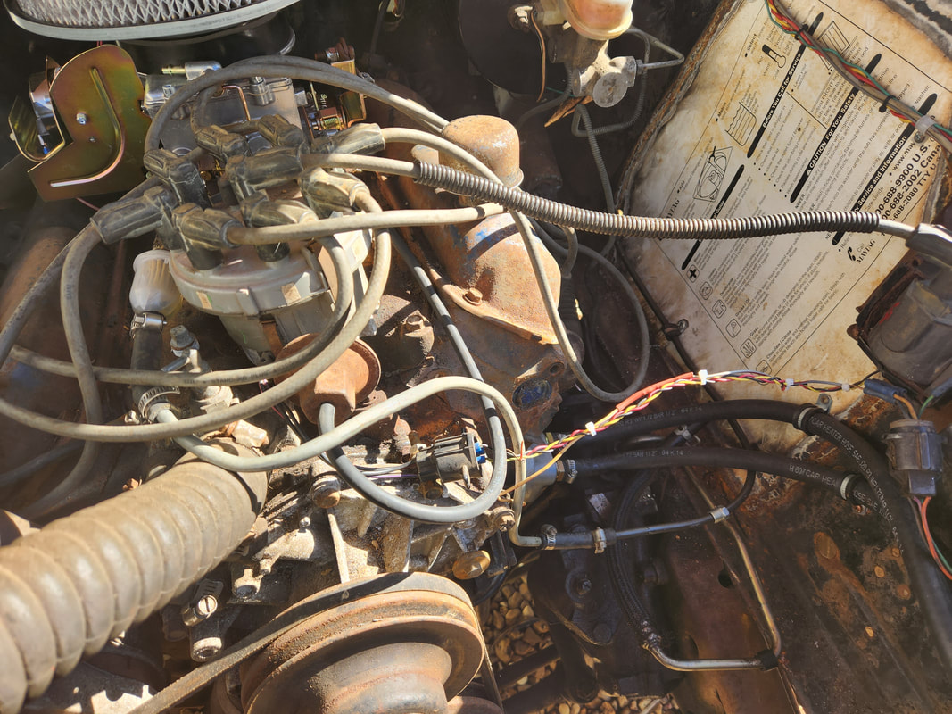
Even the extra wires that connect the Duraspark distributor to the mess to the right in the picture will also be a thing of the past with the HEI distributor installed.
Now the next thing is installing the HEI distributor. Just like on the FMT, the hookup was simple, cleaner and will be just as effective, if not more so. I removed the old Duraspark hardware and added some wire to the power wire and tach wires to reach around to the HEI cap. I set the dizzy in place and hooked everything up, and attempted another start with no success. Finally after another timing setting and giving a good dose of fuel, I got the engine started. The next problem experienced was no oil pressure. After pulling the dizzy to check the driveshaft and even pulling the valve covers to verify if any oil was getting to the top, another run attempt yielded no oil. I pulled the pan and removed the oil pump, using the driveshaft and an impact driver to check to see if it would pull and pull it did. I also had to add some tape inside the distributor shaft to keep the driveshaft from moving too far into the distributor shaft, causing it to come out of the oil pump shaft seat slightly. With the shaft fully addressed, I checked the remote oil filter assembly and found the hoses were criss-crossed. The output from the engine base was going to the output on the filter base. After correcting this problem I reassembled everything and tried again. After the engine ran for about 10 seconds I started getting oil up to the rear rocker arms. After a short while I had to put the valve cover back on to keep from oiling up the whole engine bay. During the time the engine was running, it was pumping around 40psi. Once it warmed up it went down to 20psi and once I set the idle, it went to around 10-15 psi, but would jump up with engine RPM. After running for 30 minutes the engine had to be running at a normal temp as the radiator cap didn't pressure release nor did I get any smells indicative of overheating. I shut the engine down, satisfied that the engine was fine, as the no oil noises were gone and the engine sounded nice and mean as it was supposed to.
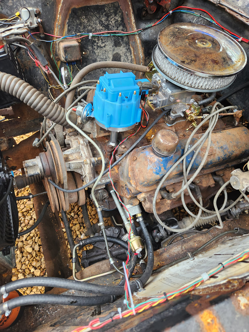
The new HEI distributor is installed after removing all the old Duraspark ignition hardware. Note how much cleaner this side of the engine bay is without all that extra hardware in place.
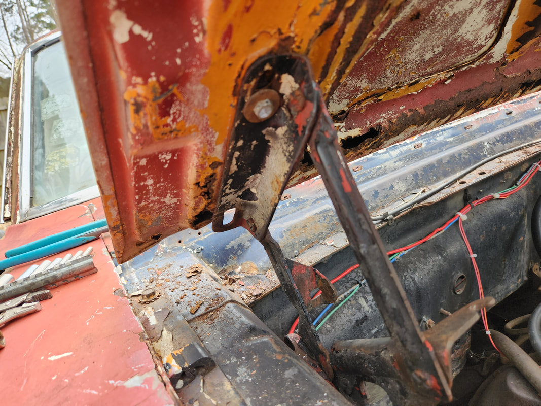
I also took a moment to set up the hood hinges by removing the springs that would've helped in holding the hood up. Since the hood is rusty and compromised, keeping the springs on would've caused the hood to fold up if I tried to close the hood against the spring tension. I had to wet these hinges with WD40 to loosen them up. I will have to use a prop rod of some sort though.
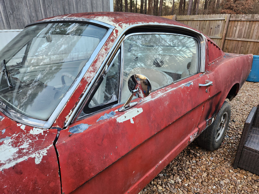
At the same time I managed to get a pair of side view mirrors and install them on the doors. Note the imprint in the paint where the old aftermarket mirrors were mounted. These mirrors are the retro style mimicking the type of mirrors that would've been on this car and similar era cars.
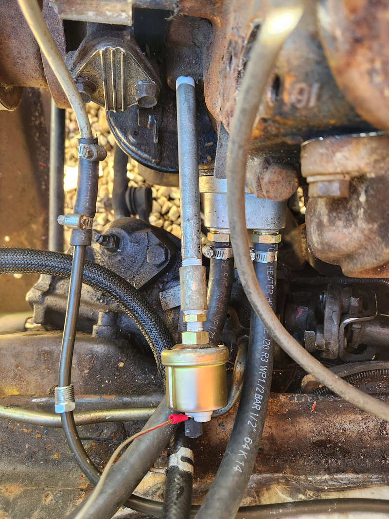
While I was at it, I addressed the oil pressure gauge sending unit when I installed the plumbing fittings necessary to put the sending unit in that came with the gauge.
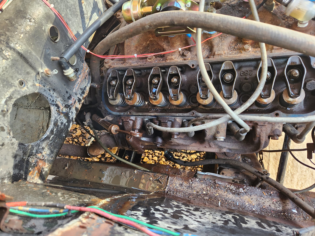
After running the engine for a good minute or so, oil pressure finally made it to the valve train, spraying oil all over the place as it spurted out from the pushrods.
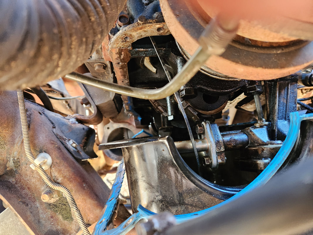
With the placement of the engine relative to the frame, I was able to drop the oil pan enough to allow me to reach the oil pump and fully remove it. I did not have to pull the oil pan at any point.
While the engine is running and idling the oil pressure was a little below 20psi, voltage was 12v, indicating that the alternator isn't charging (something I'll have to look into), and fuel levels are around 1/2 to 1/3 full based on what I put in the tank. Temp gauge wasn't reading so I will more than likely be installing a temp gauge.
In the process of testing the engine out, I did make note of the fact that the alternator wasn't charging. I ended up tracing the problem back to the voltage regulator, so I changed it out, while at the same time double checking the wiring to make sure I had all that correct, which it was. Once the charging situation was straight, I turned my attention to the transmission. After a couple successful tests, I started having issues with the transmission appearing to be stuck in a forward gear. When I put the unit in reverse, I got forward, neutral also got forward. Even when the transmission was in park the thing was still stuck in a forward gear until the parking pawl engaged. After some troubleshooting and research, I turned my attention to the valve body. I pulled it out and double checked everything, with inconclusive results. After reassembly, I tried the tranny again with the same results. At this rate further research on the same problem that others had pointed to the possibility that one of the clutch packs might be welded together or otherwise stuck. What this meant was the tranny had to come out. While this sucks, it had to be done, but at least in this truck frame and body layout, there's plenty of room to work in removing the transmission. With the transmission out, I pulled the thing apart, and found exactly what I read about. The clutch pack in the reverse/1st drum was stuck together. I pulled the lock ring out and the clutch discs were disintegrating, with the individual pieces going metal on metal, getting stuck together. With that, I will have to order another light rebuild kit to reassemble the transmission. The rest of the hardware is in good shape, so really all I have to replace is the clutch discs in the drums.
The "new" voltage regulator in place, replacing the older fat body style regulator that was in place.
On a side note, the transmission had a serious leak from around the dipstick area. This dipstick, along with the worn out O-ring, also has a crack in the cavity where the O-ring sits, allowing oil to seep out regardless of the O-ring. The dipstick tube will need replacing on the transmission.
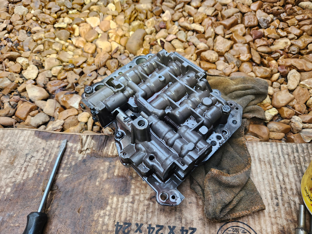
The valve body removed from the transmission during the troubleshooting of the transmission's being stuck in a forward gear.
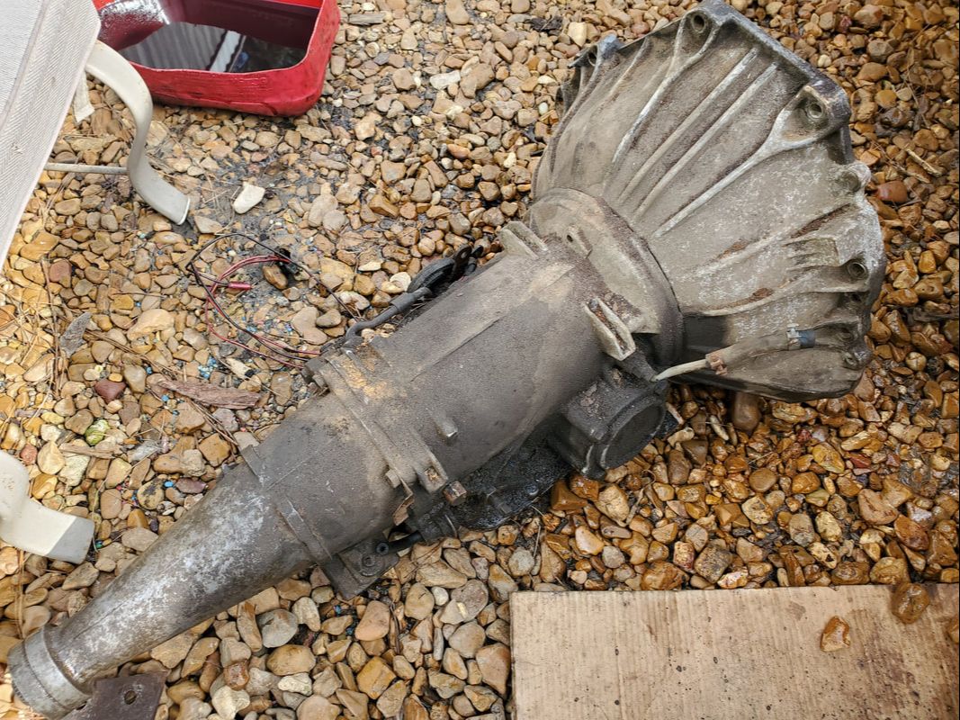
The transmission after removing from under the car, time to break this thing down.
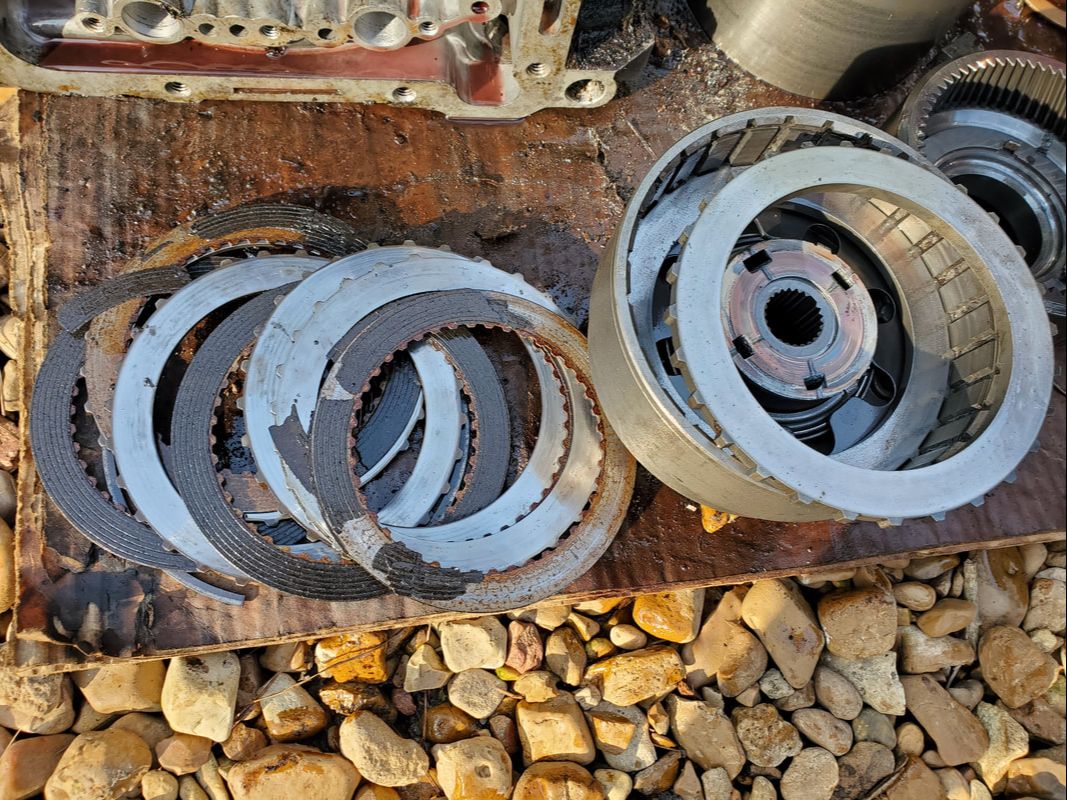
The clutch pack from the reverse/1st drum, showing the degradation of the clutch disc material and the reason why the pieces were stuck together.
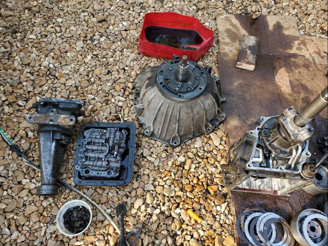
The transmission guts laid out on the ground after disassembly.
With the transmission torn apart, I took a moment to clean up everything on the machine, even the body components. I replaced all the components that were clearly worn, the clutch discs and steels, the O-rings in the different pistons, as well as the gaskets. I threw the unit back together and reinstalled the thing and was able to get reverse for a brief moment, only to lose it again. This time I tore the transmission out again, and tested the function of the bands by applying air to the ports leading to the passages from the valve body. Of course, the valve body had to come out. After confirming that everything looked straight, I put the transmission back in, a 2nd time. Still same crap. I pulled the valve body and broke it down to clean it thoroughly and tried again, with same results. I finally got a line pressure gauge and checked the line pressure, finding it to be rather high on the transmission. After a quick troubleshooting, I found that the thing that would cause this high pressure condition was lack of vacuum on the modulator. Sure enough I had none at the small manifold on the back of the intake. After cleaning out the little manifold fitting, the transmission jumped into reverse, rather hard, I might add. I also managed to make it do a 1-2 upshift as well. With the transmission issue resolved, a brief test drive provided me with a 2-3 upshift as well. The next problem on the list however is the idea that the engine begins to run rather hot after a short time. I changed the 195 degree thermostat to a 160 degree unit. I managed to slow down the climb to meltdown, but eventually the temps still started climbing dangerously high. Its beginning to look a lot like a radiator change.
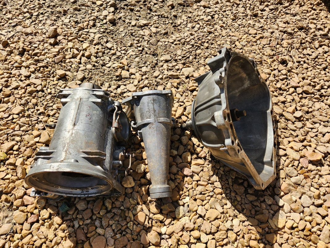
Since the transmission was broken down, I took time to thoroughly clean everything on the machine to make it look better, getting rid of the accumulated grease and dirt. The body parts are now clean, inside and out and ready for reassembly.
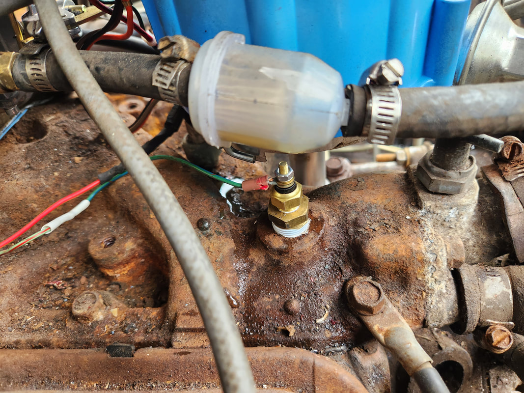
At the same time I did manage to finally get my universal temperature gauge and sending unit, which is shown here installed in a port on the intake manifold.
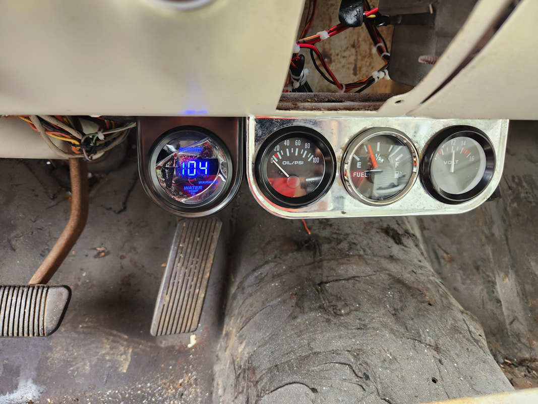
The temperature gauge is installed in a single port mounting bracket, next to the triple mount bracket. The unit defaults at 104, but as we can clearly see, it has power.
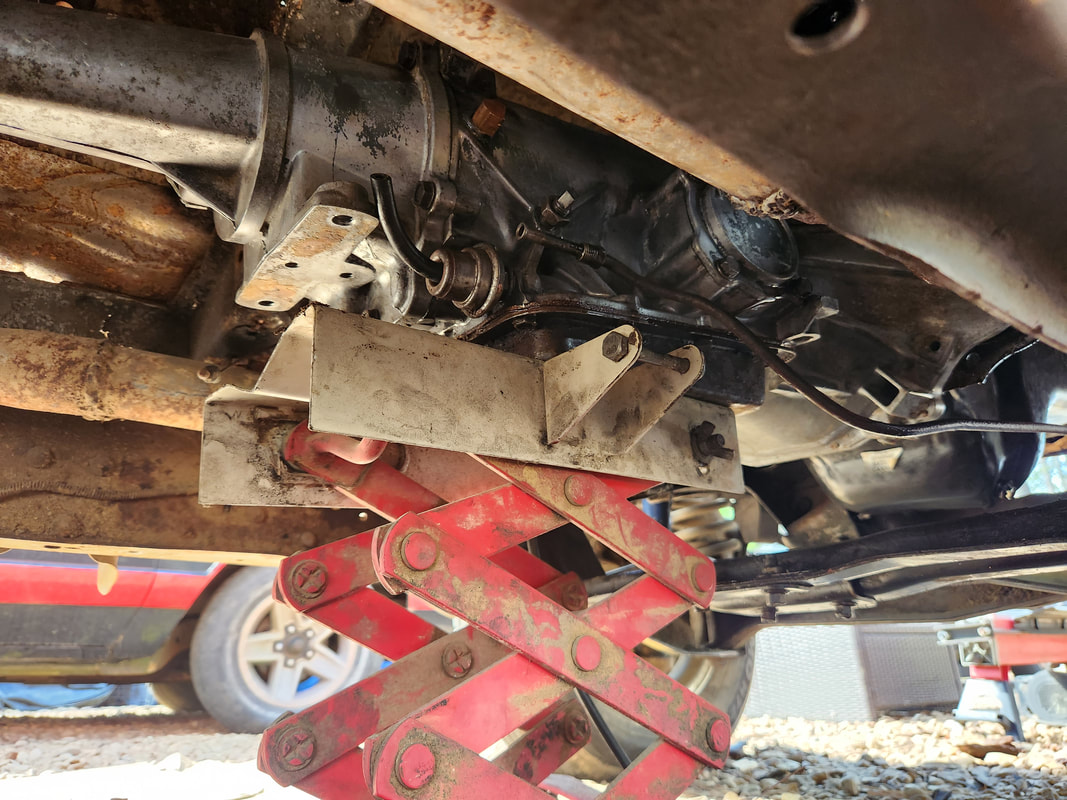
This transmission jack is a lifesaver as it makes reinstalling a transmission far easier than trying to balance the thing on a regular jack or even on your chest while trying to bench press the thing into place.
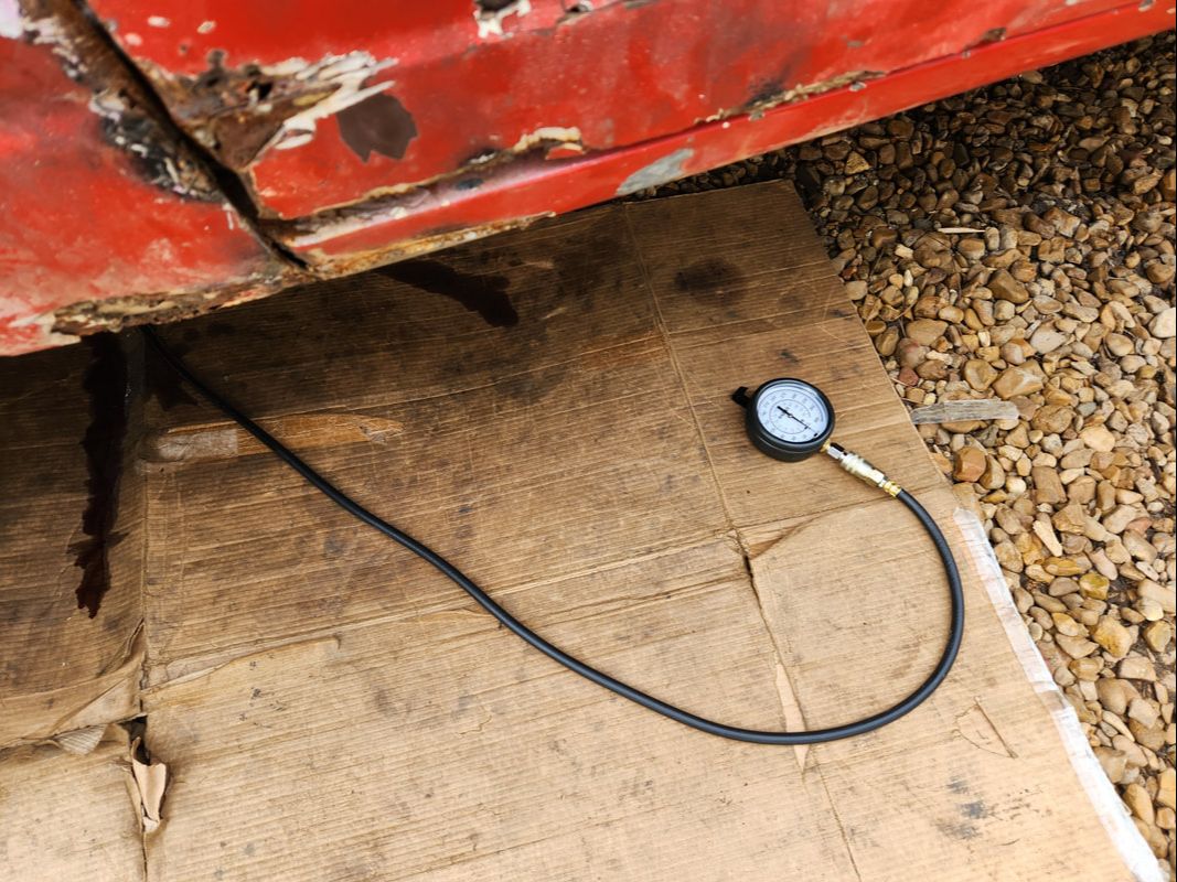
After the third attempt to get the transmission into reverse, I put a line pressure gauge assembly on the trans test port. The pressure when in reverse was almost 100psi higher than the normal range. Other ranges weren't much better, being around 75 psi higher than normal.
This little manifold for vacuum lines on the back of the intake was completely clogged with dirt. After doing a test using the distributor vacuum line to get the transmission to work properly, I cleaned this thing out and reassembled everything, getting vacuum to the modulator, as well as an apparent air leak at the brake booster, which also affected the engine idle enough for me to disconnect the brake booster hose and cap off the port. The brakes worked just fine without the power assist anyway.
After an issue that I had with the engine creeping into the overheating range, I had to swap out the radiator. The old brass radiator on this car is small, as is the case on the 65 year Mustangs, and this one was over 30 years old and possibly clogged in spots. I also swapped out the thermostat with a 160 degree unit, and even after doing this, the engine would hold around 180 for about 20 minutes before creeping up higher and higher until its running past boiling temperature. The new rad I grabbed was an aluminum unit that was a little thicker, which combined with the 16" fan, should be more than able to cool the engine. With the installation of the new rad, I had the engine running around 30 min or so and the temperature held around 175 degrees, give or take a few.
The old brass radiator on the 65 year Mustang is smaller than the ones in the later Mustangs like the 69. These rads aren't even much thicker either. This puts a narrow window of cooling ability before the engine begins to run hot. This rad being over 30 years old also doesn't help matters.
The new aluminum radiator that is a direct fit for the old radiator, with a little extra thickness.
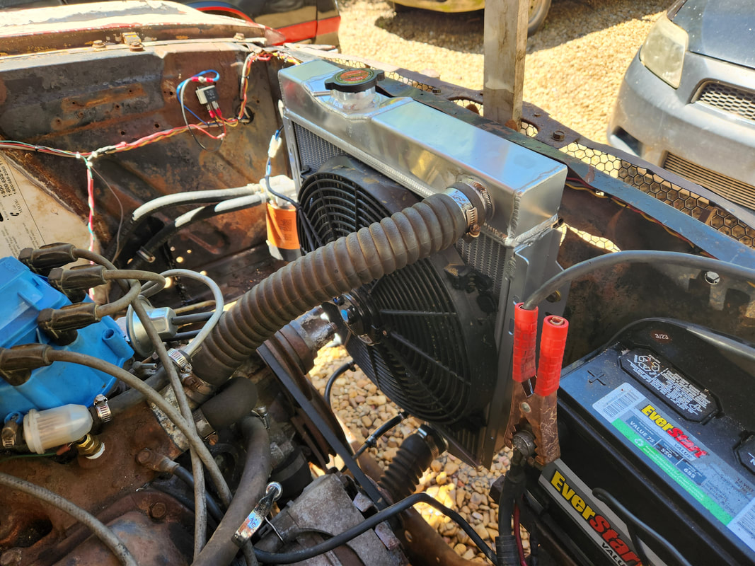
The new radiator in place with everything hooked up as it was on the old radiator. Let's see if this works.
