1951 Chevy Suburban Panel Truck
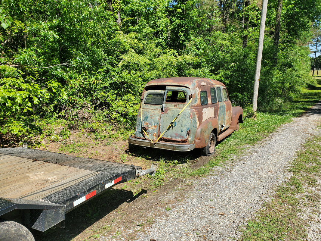
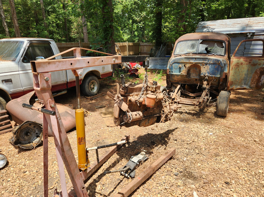
We have a helluva treat for you my fellow readers and car nuts. We managed to pick up while on a vacation in Texas, a 1951 Chevy Suburban panel truck. This truck was on my saved list on facebook marketplace for some time during our plans to go to Texas. My plan was to do some searching for car parts that I either need for current projects or can use for future projects and if something presents itself, a whole vehicle will be picked up.
We made our way from Galveston up to Houston after the tourist/vacation part of our trip was done. It was here, just outside of Houston, where this truck was located. After looking the truck over and getting the story behind it, we negotiated the price down from the original $1k price it was listed at to $800. Now while the truck was paid for and ours, we didn't have any means to pick this truck up as we were on vacation and the truck we rented did not have a class 3 hitch that could pull a car trailer. We would have to come back later to pick this truck up when we could rent the more powerful 3/4 ton diesel truck that we typically rent when we go to haul a car.
We made our way from Galveston up to Houston after the tourist/vacation part of our trip was done. It was here, just outside of Houston, where this truck was located. After looking the truck over and getting the story behind it, we negotiated the price down from the original $1k price it was listed at to $800. Now while the truck was paid for and ours, we didn't have any means to pick this truck up as we were on vacation and the truck we rented did not have a class 3 hitch that could pull a car trailer. We would have to come back later to pick this truck up when we could rent the more powerful 3/4 ton diesel truck that we typically rent when we go to haul a car.
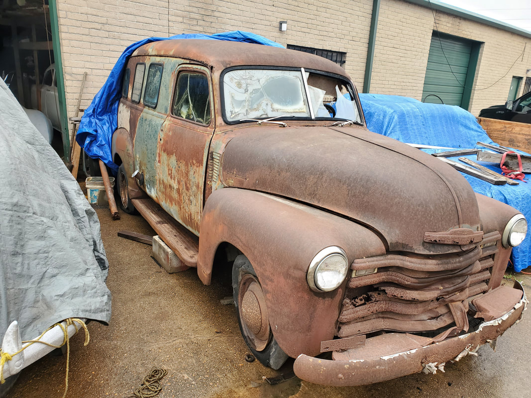
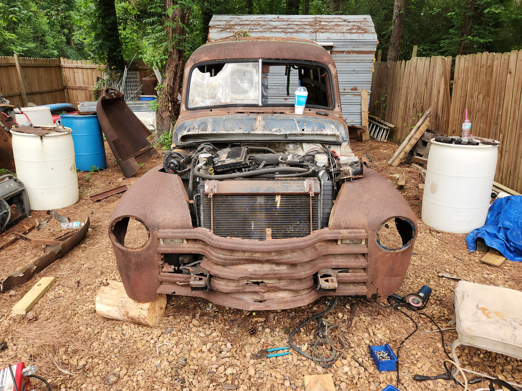
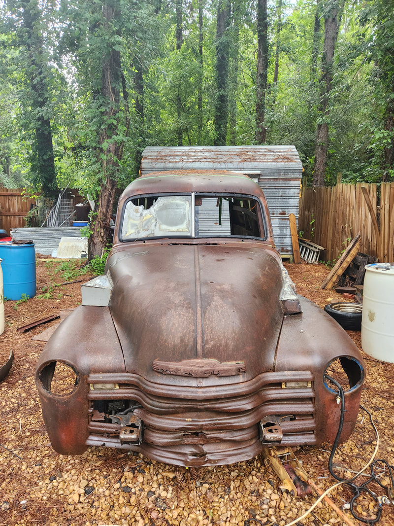
Shot of 51 Chevy at shop where we bought it.
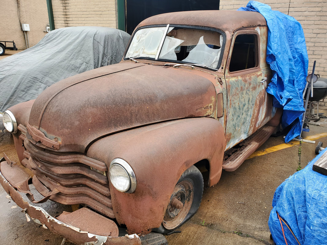
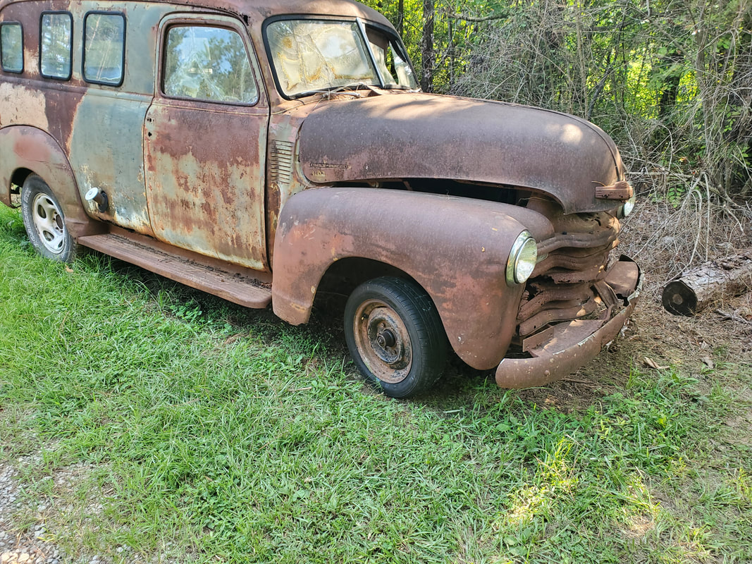
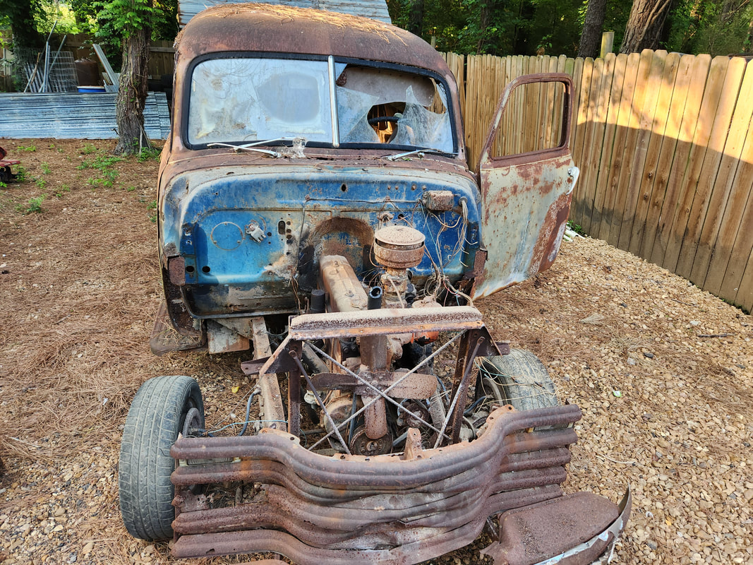
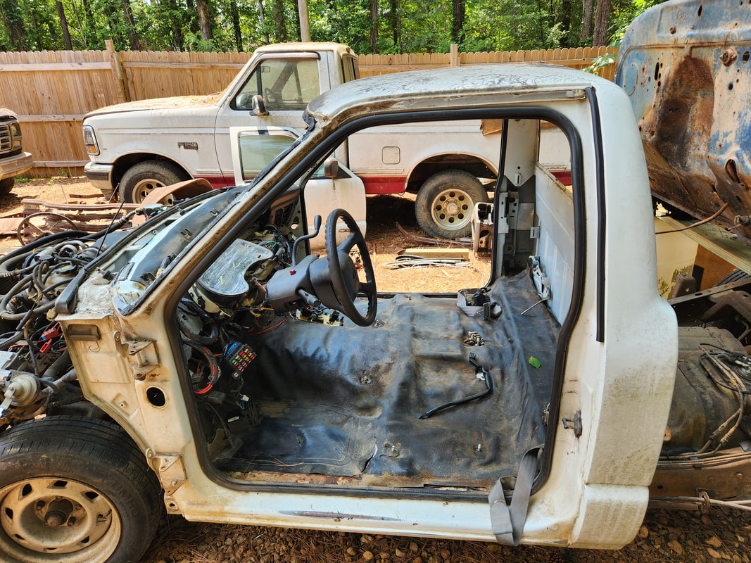
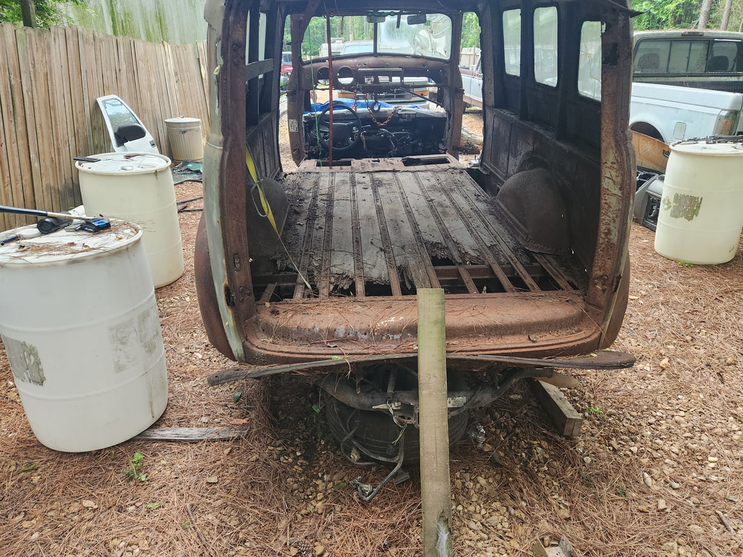
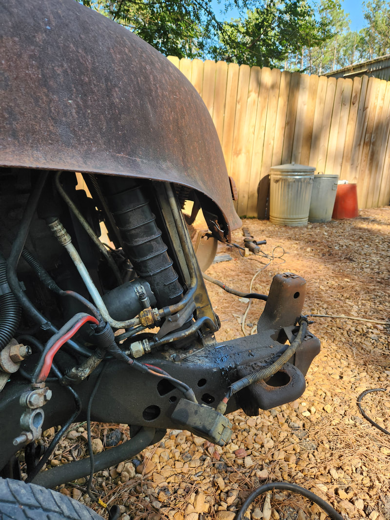
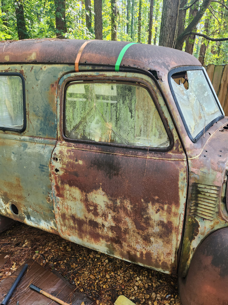
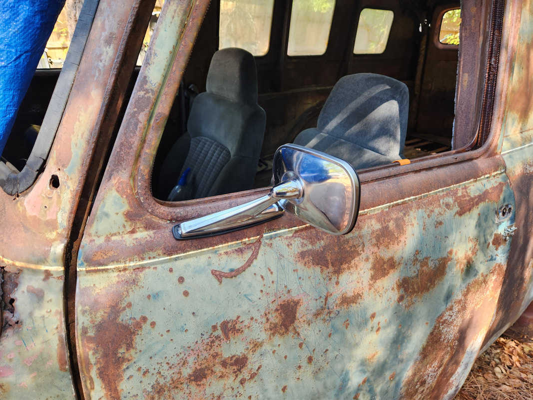
Left side shot showing everything there.
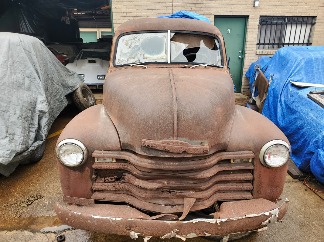
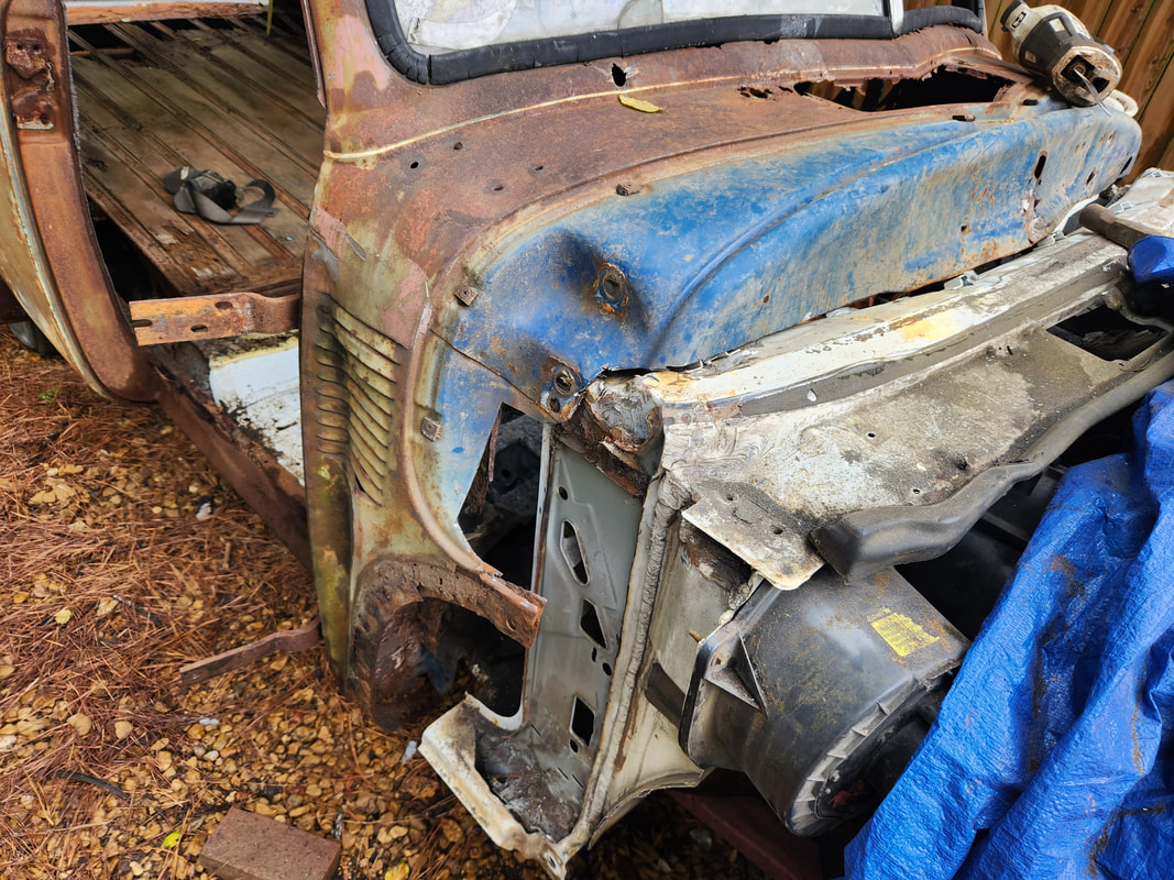
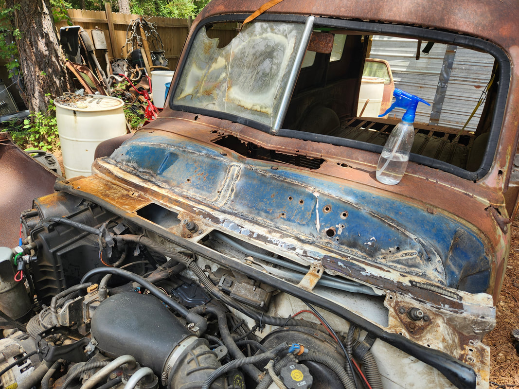
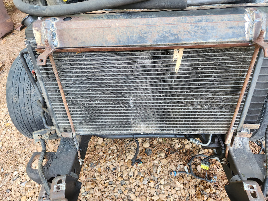
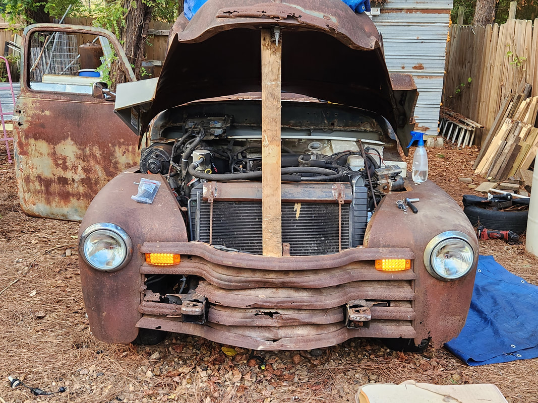
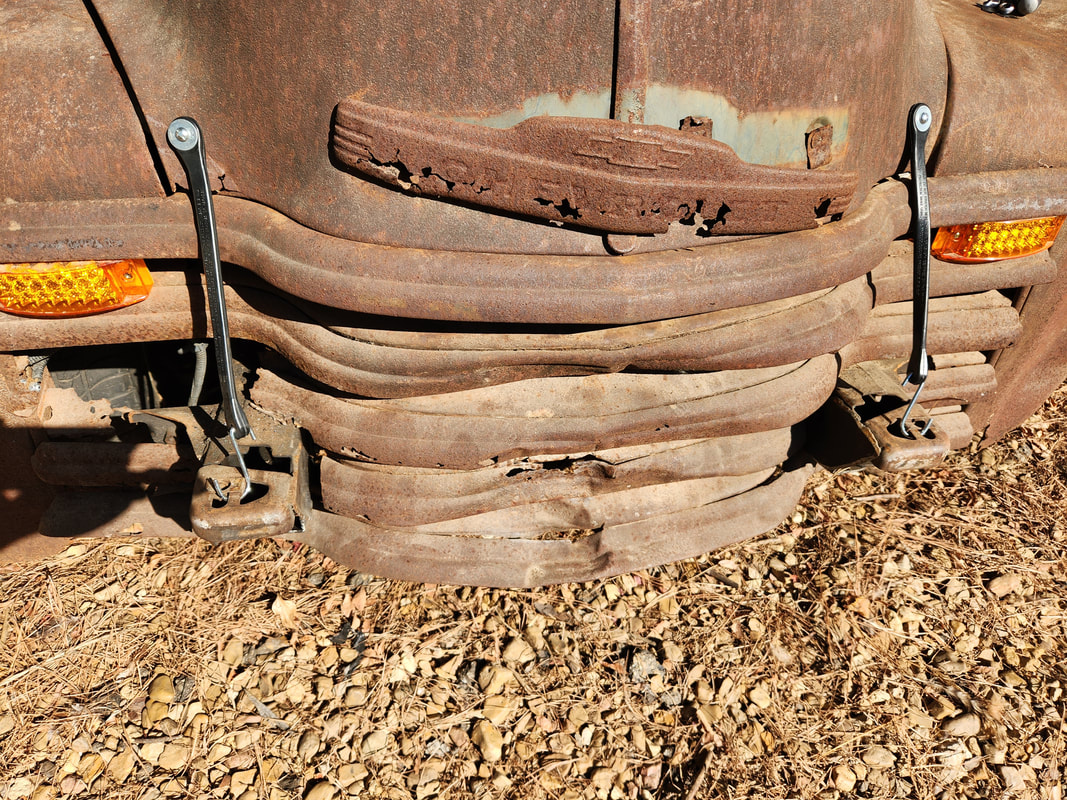
Front end shot showing rusted grille in close up detail.
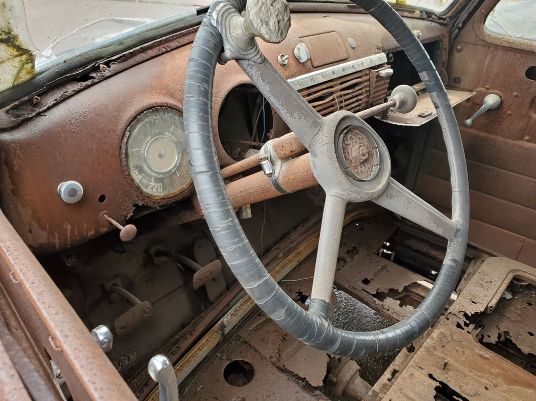
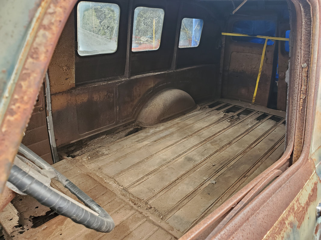
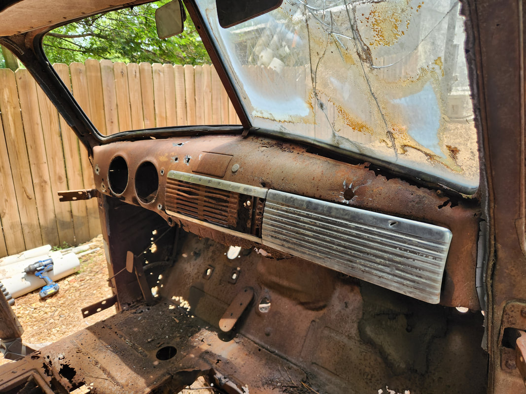
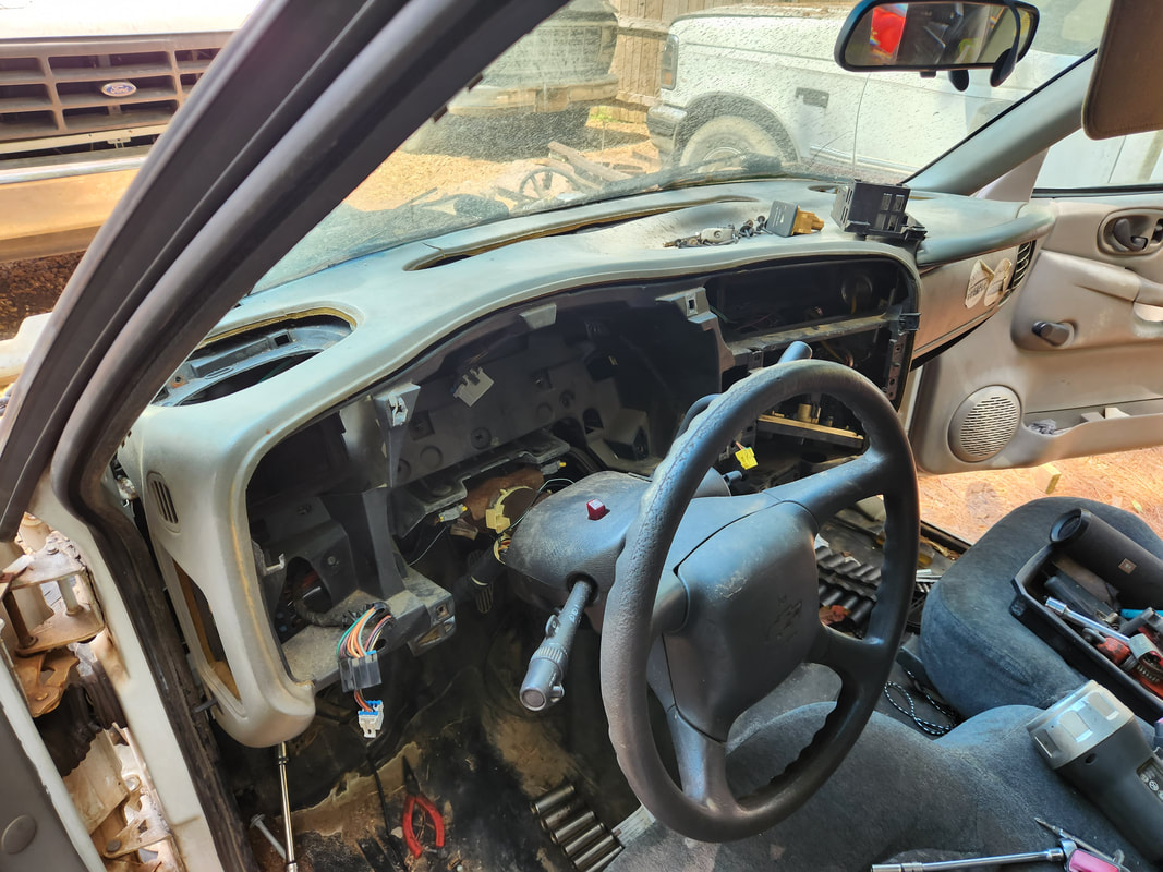
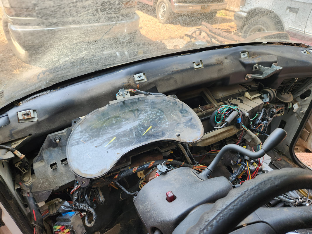
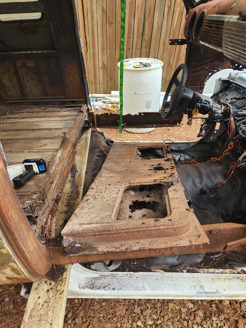
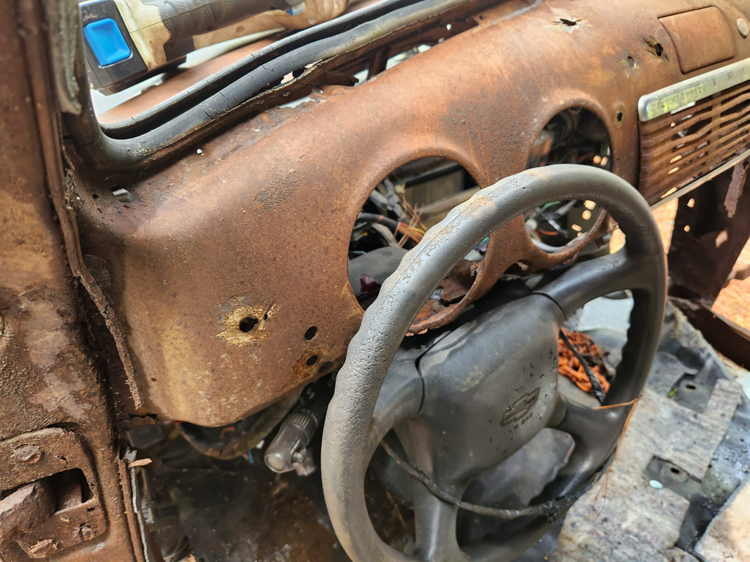
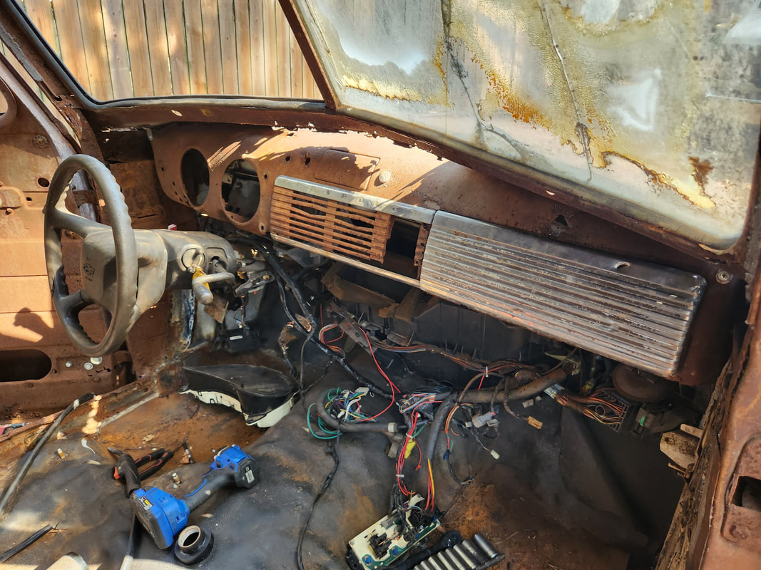
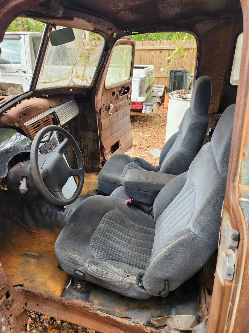
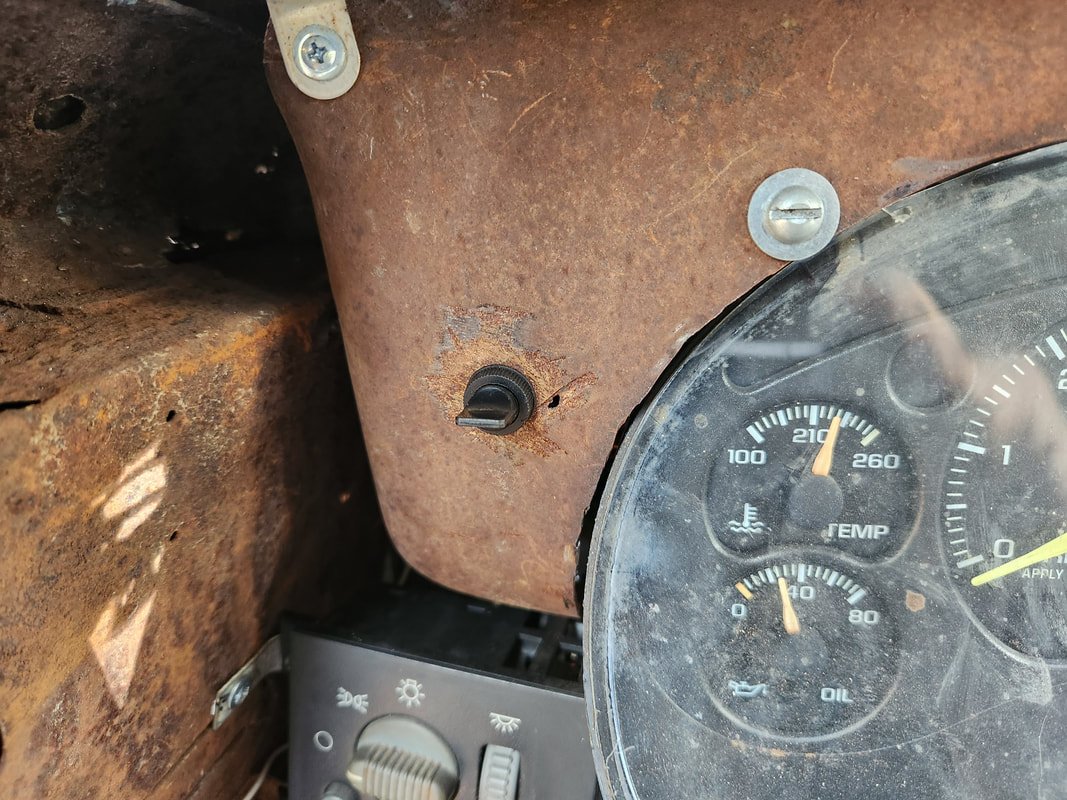
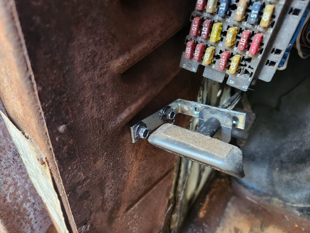
Interior showing rusted floor, dash panel with missing gauge, and other details of the interior.
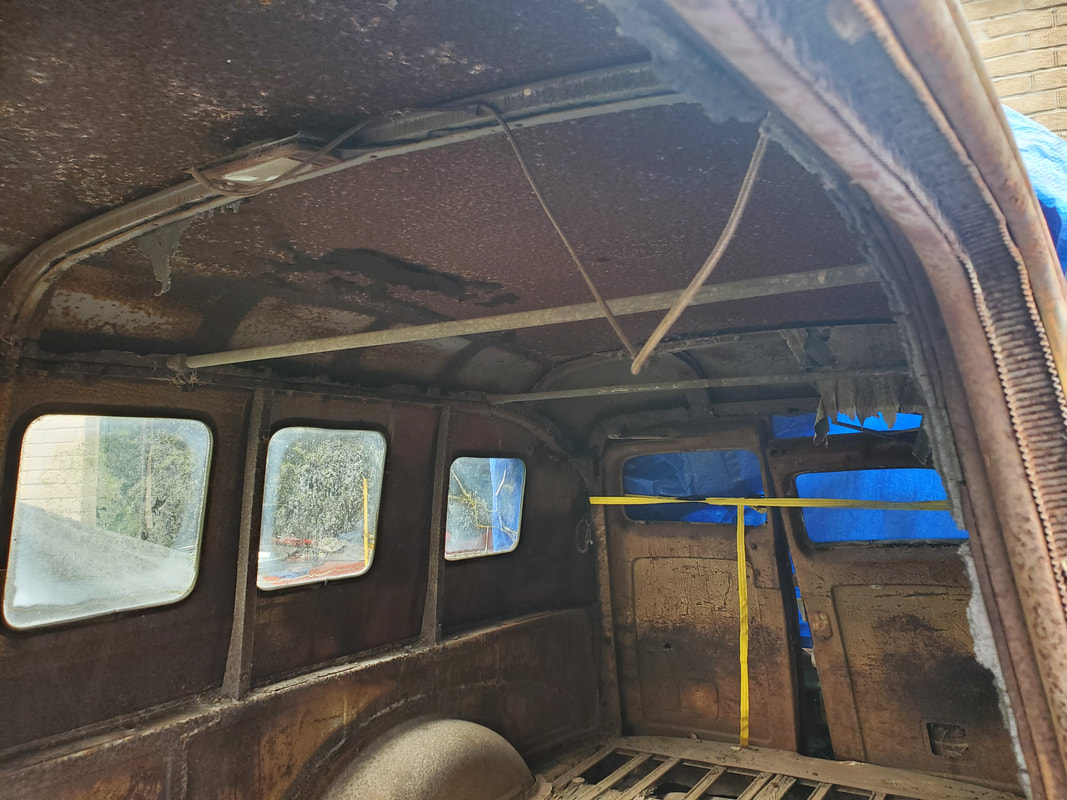
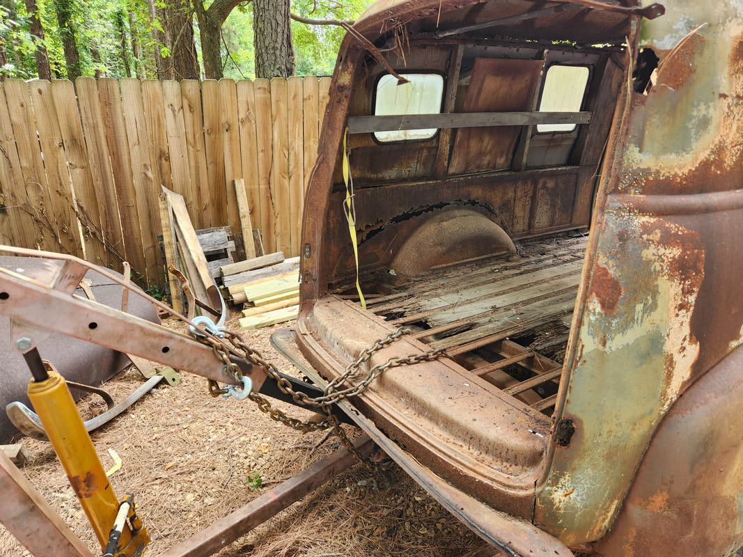
Better shot of the ceiling showing headliner support bars.
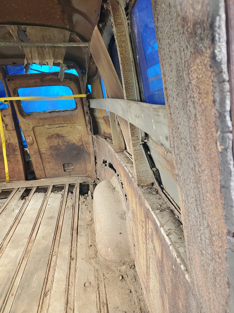
Another angle of side with rust damage.
We waited until the following weekend from when we returned home to go back out to Texas to pick up the truck. We also ended up borrowing our neighbor's bigger trailer that was more suitable for making the long distance run since our car trailer had balding old tires and because I didn't have a hitch with an offset tongue, the trailer would've been at a steep angle that would've had most of the weight on the rear axle. Trying to drag a 2 ton truck on one axle most of the time with balding tires for hundreds of miles might not have worked all to well.
With the trailer in tow, we left in the morning and cannonballed it to the guy's shop in Texas. Once there we had to use the big truck to pull the old truck from its spot and get it staged in the thoroughfare. From there I pulled the truck and trailer around, staging the back of the trailer to the back of the old truck so we can try to pull it up on the trailer. Well, since the wheels were all flat and almost shredded and the brakes were frozen, trying to use a manual winch was a fruitless attempt at trying to pull the truck on to the trailer. Luckily by the grace of God the guy was able to borrow a forklift from one of his neighbor shops to pick the truck up and push it onto the trailer. I was more than happy to throw a few bucks to dude for that little bit of help. With the truck strapped down we were ready to ride out.
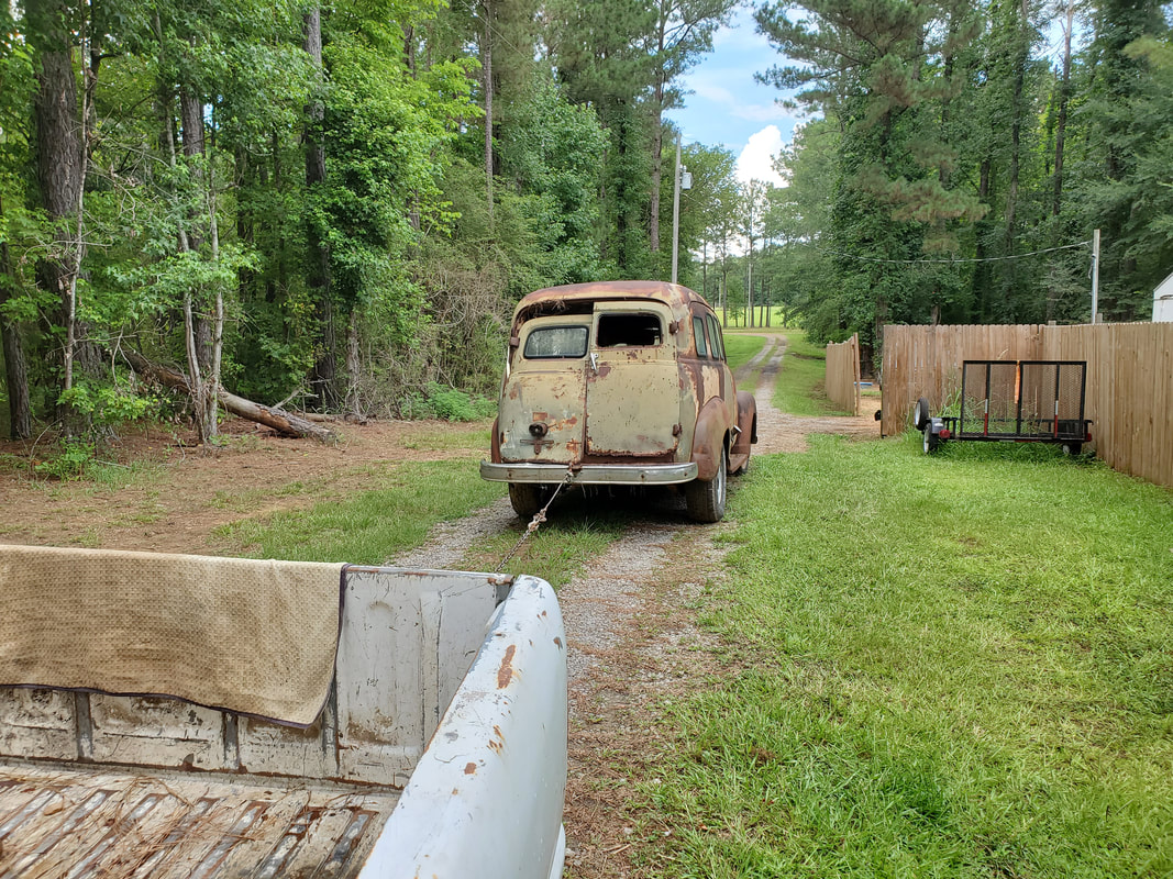
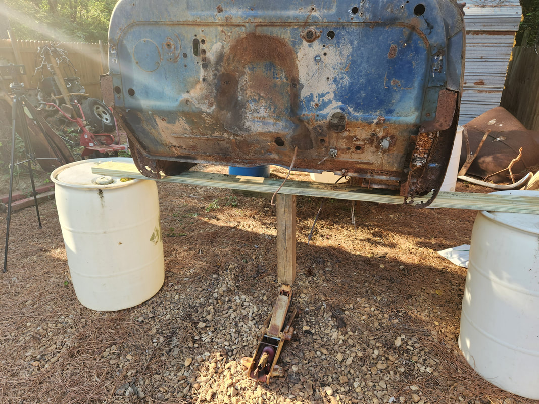
We had other business to tend to while in Texas so we went ahead and took care of that before hitting the road the following day to head back home. After another long drive back home, we arrived at night, too late to be trying to get this truck off the trailer. I did come up with a plan though to easily get the truck off the trailer. I took a few moments to stage the back of the trailer close to the power pole that is next to the main driveway. In the process of staging the trailer I did get the whole truck/trailer rig off and alongside the driveway. My plan would be to attach a tow strap around the pole then attach a tow chain between the strap and the front of the truck, then drive the trailer forward, letting the strap pull the truck right off the trailer.
The following morning I put my plan into action. I took the tow strap and wrapped it around the power pole, hooking both hooks together. From there I hooked a chain to the pair of hooks then around the K member of the truck. From there I set up the ramps and slowly started pulling the trailer forward. I managed to slowly get the front wheels on the ramps, then on the ground. Inching forward, stopping to check now and again, I got the rear wheels on the ramps then on the ground. Moving forward I managed to get the trailer clear of the back of the Chevy and out of the way.
With the trailer in tow, we left in the morning and cannonballed it to the guy's shop in Texas. Once there we had to use the big truck to pull the old truck from its spot and get it staged in the thoroughfare. From there I pulled the truck and trailer around, staging the back of the trailer to the back of the old truck so we can try to pull it up on the trailer. Well, since the wheels were all flat and almost shredded and the brakes were frozen, trying to use a manual winch was a fruitless attempt at trying to pull the truck on to the trailer. Luckily by the grace of God the guy was able to borrow a forklift from one of his neighbor shops to pick the truck up and push it onto the trailer. I was more than happy to throw a few bucks to dude for that little bit of help. With the truck strapped down we were ready to ride out.
We had other business to tend to while in Texas so we went ahead and took care of that before hitting the road the following day to head back home. After another long drive back home, we arrived at night, too late to be trying to get this truck off the trailer. I did come up with a plan though to easily get the truck off the trailer. I took a few moments to stage the back of the trailer close to the power pole that is next to the main driveway. In the process of staging the trailer I did get the whole truck/trailer rig off and alongside the driveway. My plan would be to attach a tow strap around the pole then attach a tow chain between the strap and the front of the truck, then drive the trailer forward, letting the strap pull the truck right off the trailer.
The following morning I put my plan into action. I took the tow strap and wrapped it around the power pole, hooking both hooks together. From there I hooked a chain to the pair of hooks then around the K member of the truck. From there I set up the ramps and slowly started pulling the trailer forward. I managed to slowly get the front wheels on the ramps, then on the ground. Inching forward, stopping to check now and again, I got the rear wheels on the ramps then on the ground. Moving forward I managed to get the trailer clear of the back of the Chevy and out of the way.
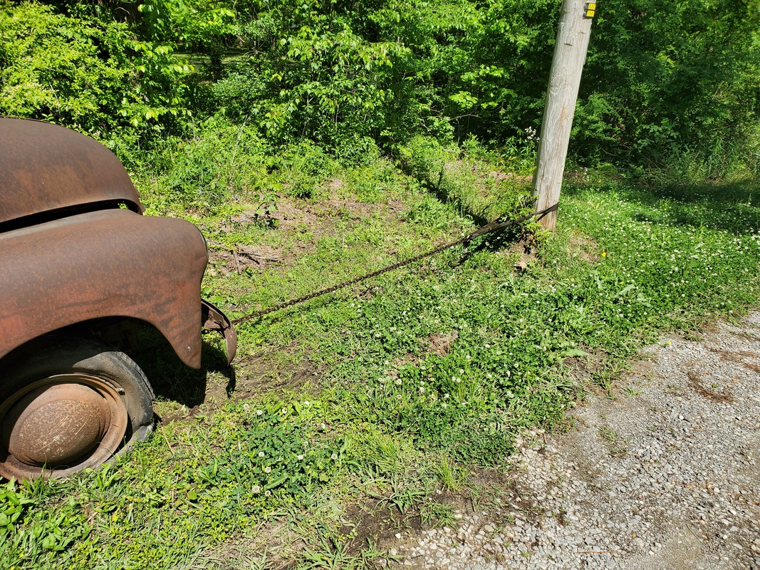
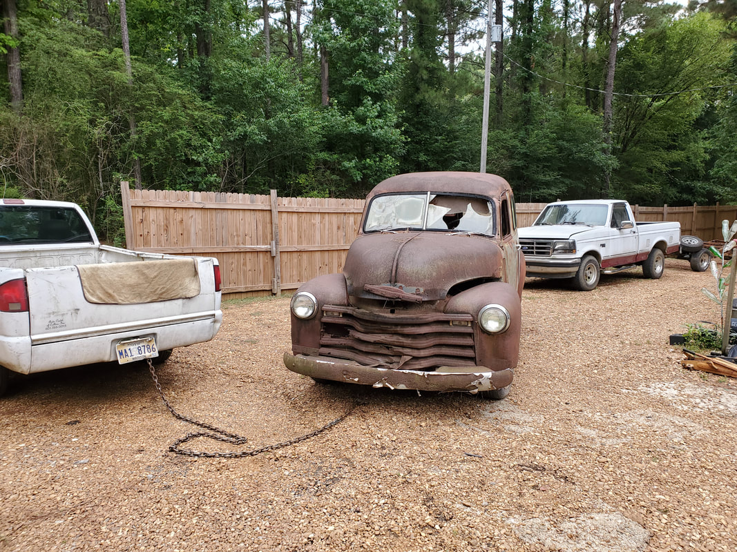
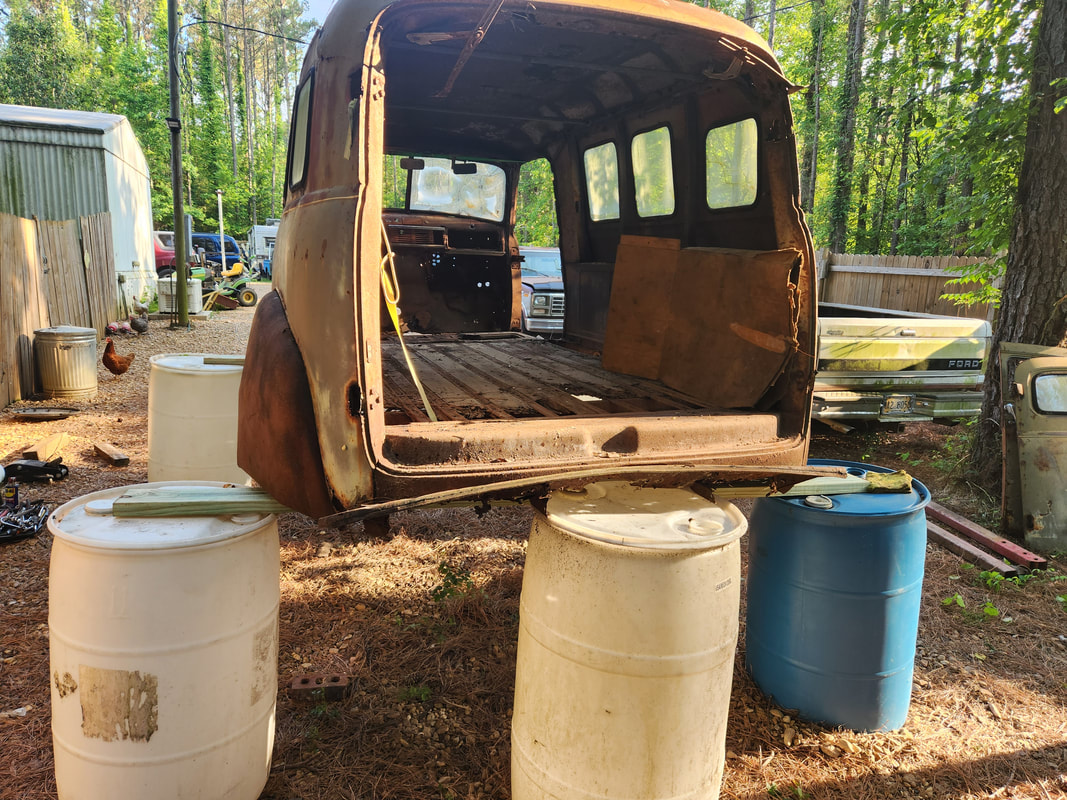
Truck's front end chained to power pole while pulling it free from trailer.
With the truck on the ground, I had to take a manual winch and hook it up to the tow strap and to the chain to pull slack into it by pulling the truck forward some so I could unhook the chain from the truck's K member. I only had to go a few inches to manage this. Once I had my equipment removed and stowed away, I gave the truck another once over to see what all was up on it as I needed to come up with a battle plan to tackle this project without it being too much.
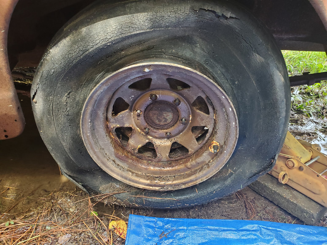
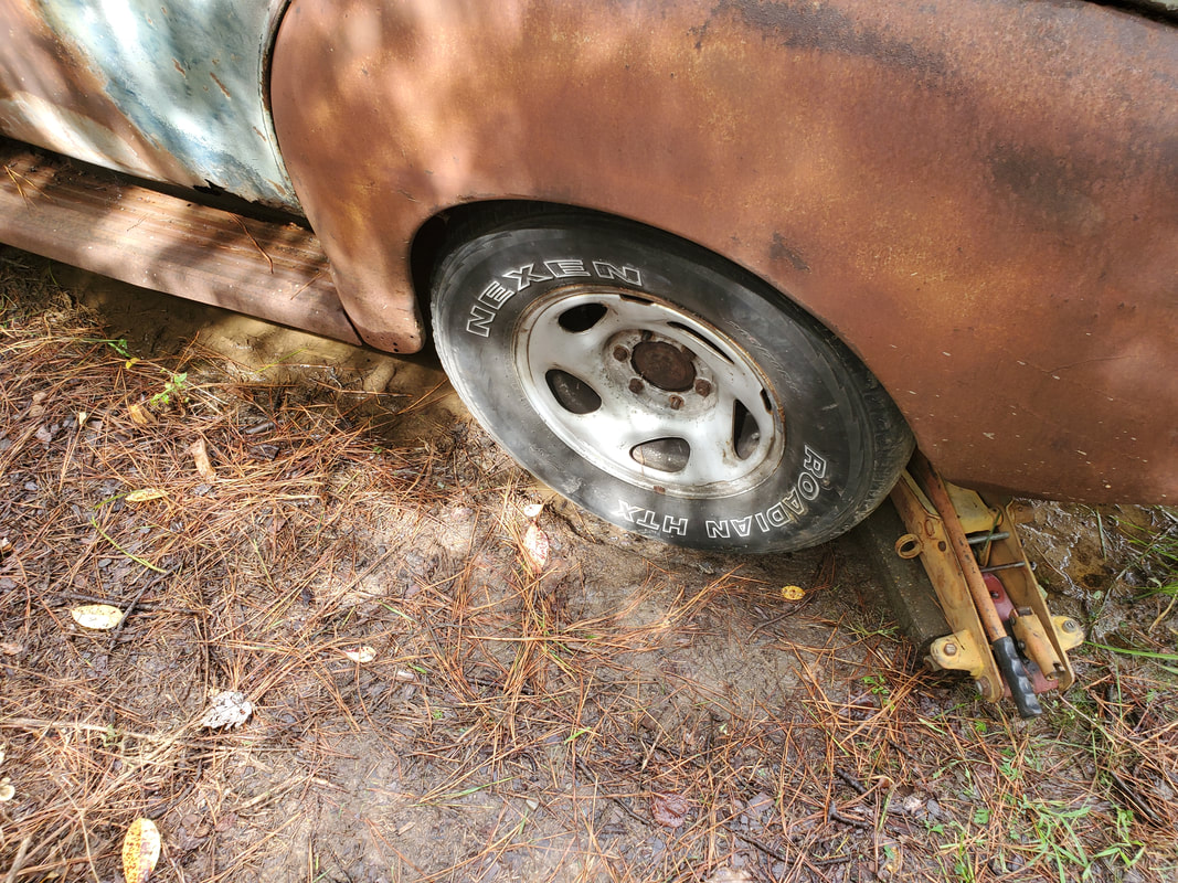
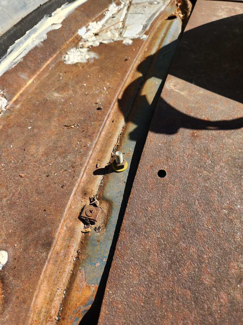
Another thing that I looked at is the rusted and pitted rims on this truck, which will need to be replaced or substituted along with the wheels in order for me to be able to move the truck around the yard. The LUV's wheels are also 6 lug and turned out to be the same 5.5" bolt pattern as the 51, so I was able to use the spare rim from the LUV.
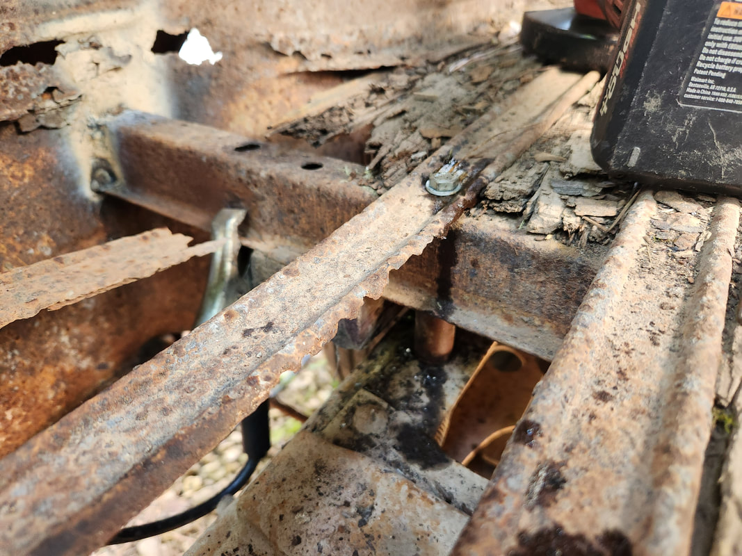
Brake drum soaked with WD40 to help in breaking the thing free. Luckily the lug nuts on these wheels didn't give me any issue. The exception was the left rear rim, a couple of the lugs were rusted away enough that they were no longer 3/4" but one lug was able to have an 18mm socket hammered on and the other took a 16 mm. After hammering the sockets to the lugs, the impact wrench was able to quickly back the lugs off.
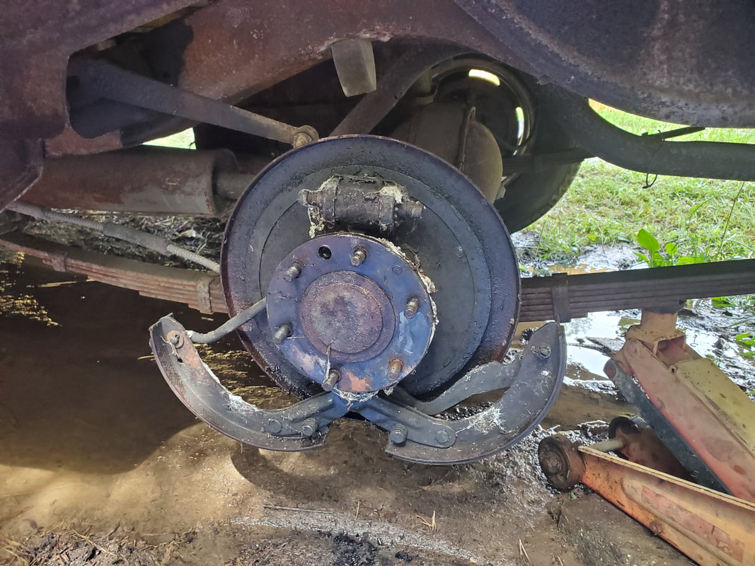
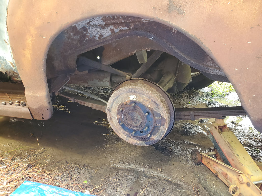
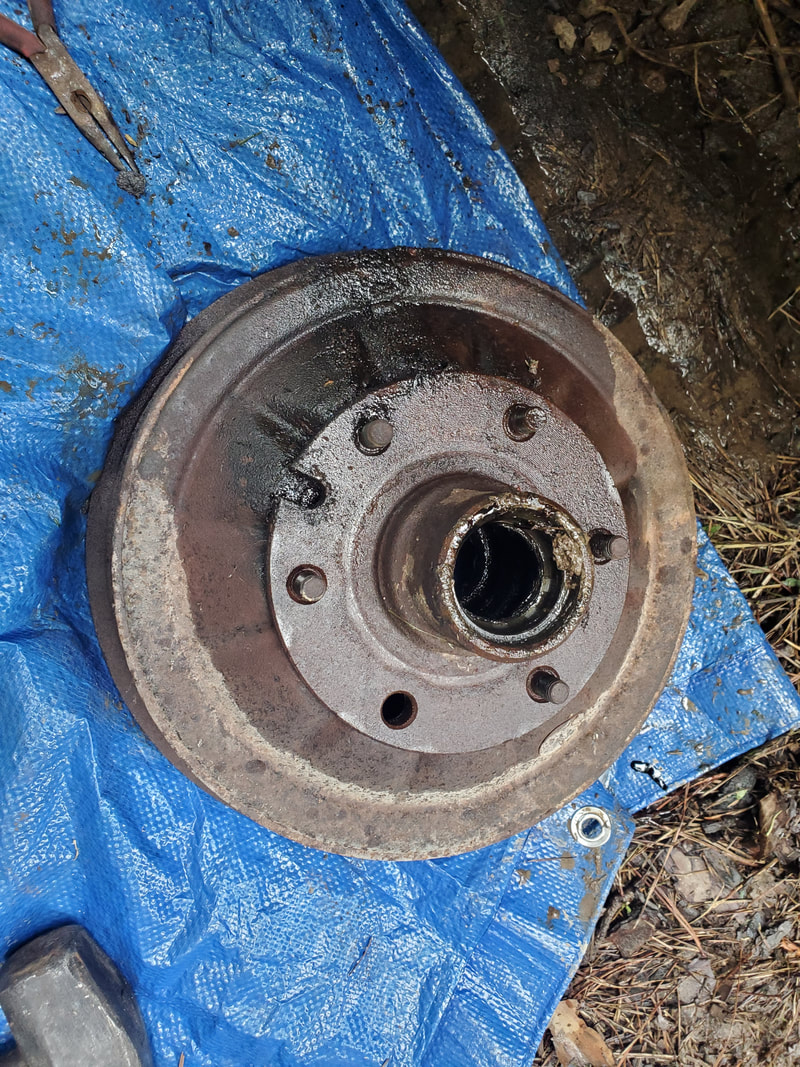
With the rim off, the fun began. I started working my way around the drums with the baby sledgehammer as well as a large flathead screwdriver, which was used to pry on the drums to help back them off each axle. After a while I had the drums backed off enough that I was able to get the crowbar in to put more leverage on them. After more beating I finally got the drums off. Next I would have to remove the old brake shoe and associated hardware so when I put the tire on without the drum in the case of the rear brakes, there will be nothing to possibly freeze up again in the future. In the case of this wheel, the spring to the shoes was broken so the top portion came loose, there was just a matter of removing the retaining clip holding the peg that held the bottom of the shoes in place.
With the hardware removed I was able to put the replacement rim/tire on the hub. We managed to get a trio of 16" Toyota truck rims with tires on them from a friend of ours who didn't need them. The 6 lug rims are the same bolt pattern for the Toyota truck as they are for the Chevy truck. I put the wheel on and moved on to the right side, repeating the same fun on that side before being able to get the wheel on.
Moving on to the front, I had to place my jacks since I had to drag out another one, in certain spots to facilitate jacking up the vehicle high enough to allow me to be able to get the wheels on when I go the brake hardware off. The steering mechanisms along with the sway bar would all interfere, along with the soft ground. I had to jack the truck in two different spots then put a ramp under the frame behind the steering mechanism to add some extra support. As with the other rims, the lugs didn't give me much grief to come off. Unlike the rear brake drums, the left front wheel was rather stubborn. I had to beat the shit out of the drum, even after removing the wheel bearings I still had to beat on the thing to finally work the thing free from the spindle. Note how the drum is soaked from WD40.
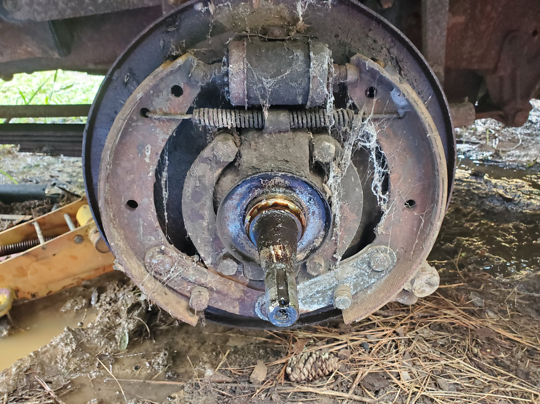
As before, I wanted to remove the brake hardware so in the case of the front drums, when I put the drum back on, there won't be anything to resist or possibly bind up again in the future. I had to pry on the tops of the brake shoes to get them free from the wheel cylinder and get the spring off then remove the clip that held the peg in place at the bottom of the shoes. Once that was done the two brake shoes came off. I was able to re-install the drums, but then I ran into another serious problem.
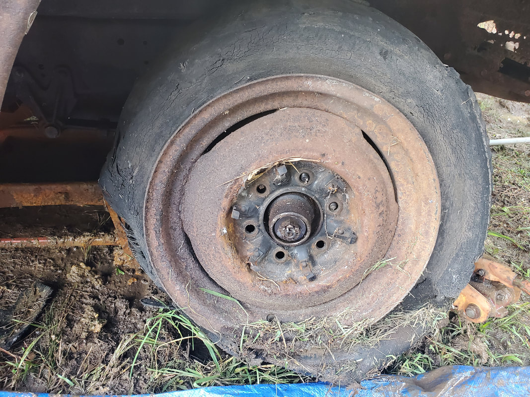
The problem that I had was when I tried to put the third Toyota rim on the front. The hub offset was different on the Toyota rim compared to the stock old Chevy rim. The distance from the back of the rim mount surface to the bead of the rim on the stock rims was 3.75", the Toyota was 5" or so. This large distance caused the inner bead of the rim to extend too far in and make contact with the steering tie rod end and knuckle on the spindle, not allowing the rim to sit flush on the brake drum. Because of this, the Toyota rim couldn't be used, I'd have to try and get a tire on the old rim after removing the shitty tire and reuse that old rim. Of course the same will apply to the right side as well. At least with the car ramp under the frame I could recover my jacks until I can put the new tires on.
Right front tire on with fresh used tire. The spare LUV rim is on the other side on the front. Front tires are smaller than rear tires as we wanted to make sure these tires will clear everything underneath the body when the wheels are turned.
After a span of time, I finally got around to clearing up things in the yard to allow me to move the 51 within the fence. Here the S10 is pulling the 51 Chevy from its resting spot alongside the driveway, getting it staged to be worked into the yard.
At this point the truck was turned to get the rear end pointing to the back, to get the truck to move backwards to its next resting spot. The big Tracker was used on the right side to help in working the 51 into this position alongside the S10.
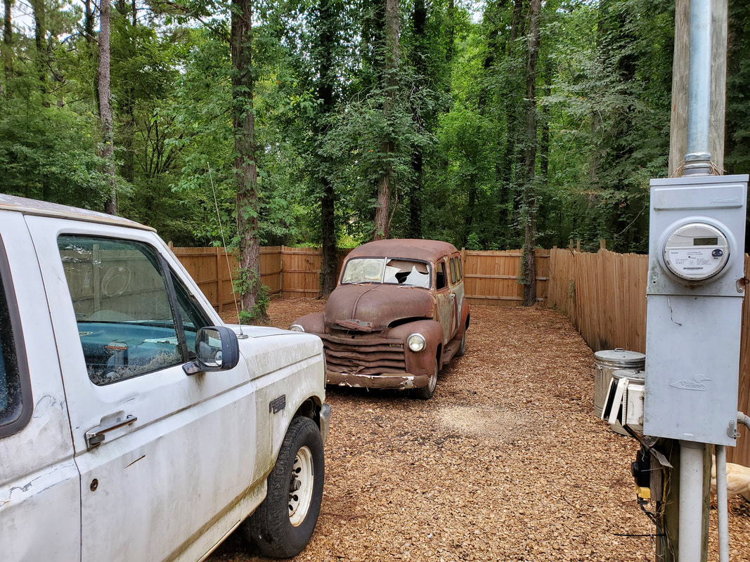
The 51 is now in its resting spot, courtesy of the F250 being used as the last tether vehicle to help slowly walk the truck down to this point.
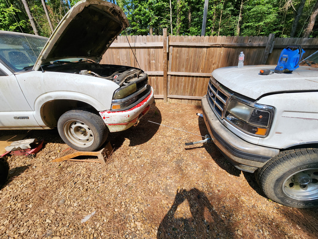
Speaking of the S10, I had decided to proceed with the build of the 51 using the S10 as the basis of the build. I've seen others take modern vehicles and chop them down enough to allow for the fitment of an old body while still retaining all the modern electronics and hardware of the dash and computer and steering so the final product will be a modern vehicle with an old body. Only problem with the S10 is the transmission has been failing for the last couple years and we've been putting off this swap job as I knew it would be a PITA to do. But if I want to proceed with the 51 build, I need to get this transmission problem addressed now so I don't have to address it later when I'm trying to focus on building the old truck. After getting the truck on the ramps, since one side was not quite set in the cradle of one of the ramps, for safety I added wheel chocks in the back so when the driveshaft is removed, the truck doesn't just roll down. The come-a-long is attached between the fronts of both the S10 and FMT to have some redundancy in case the wheel chocks don't quite work so well.
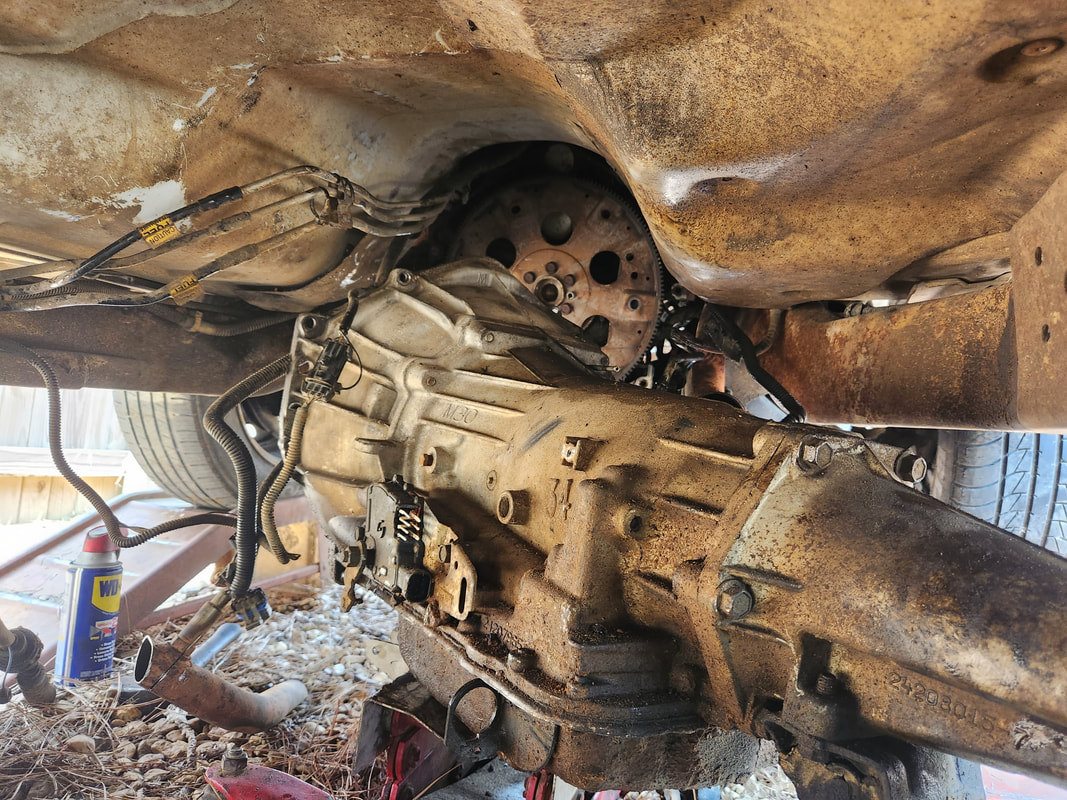
The transmission is finally on its way down and out from the truck, courtesy of the transmission jack. After installing the replacement transmission and patching the exhaust pipe that I had to cut during the initial extraction, I was able to get things straight so I can test out the truck.
After testing out the S10 successfully, with only a small anomaly noted when I tried to push the truck to over 60, I was satisfied enough to write this part of the project off. It appeared like the torque converter was jumping in and out, which might indicate a failing TC, which if this is the case, I'll have to address this later on. But all in all, the truck did drive way better than it did with the old transmission. So now, the next move is stripping down the 51 of all body panels and parts, including the powertrain, until I get down to just the raw shell. The plan is to do the same thing like with Truckstang, get the body, lightened after removing everything, and support it on the boards held up by the drums so I can roll the stripped down S10 chassis underneath the body and work to get the body sized up for fitment onto the S10 chassis.
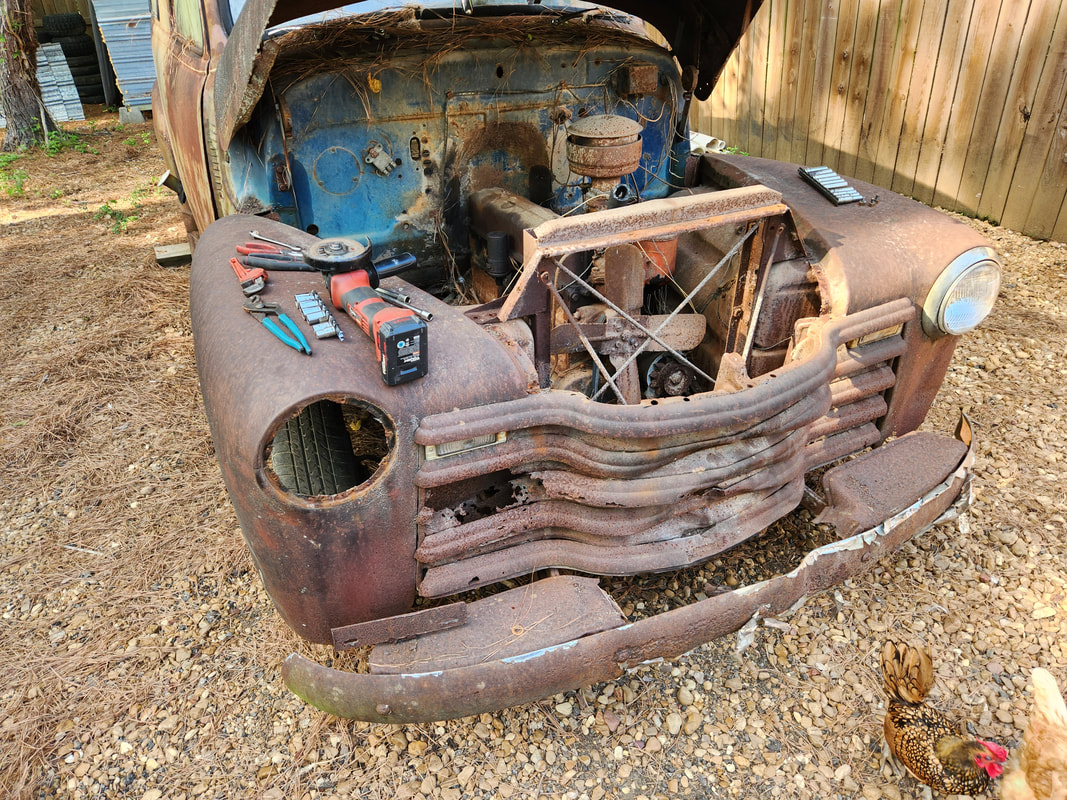
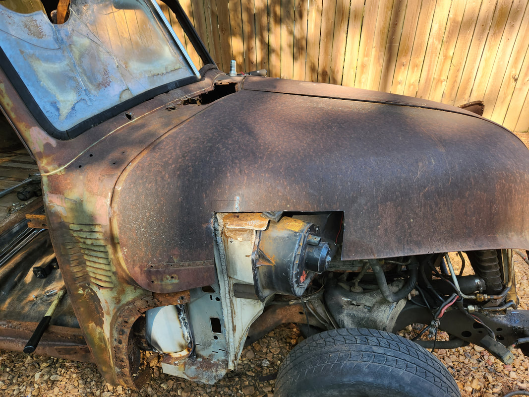
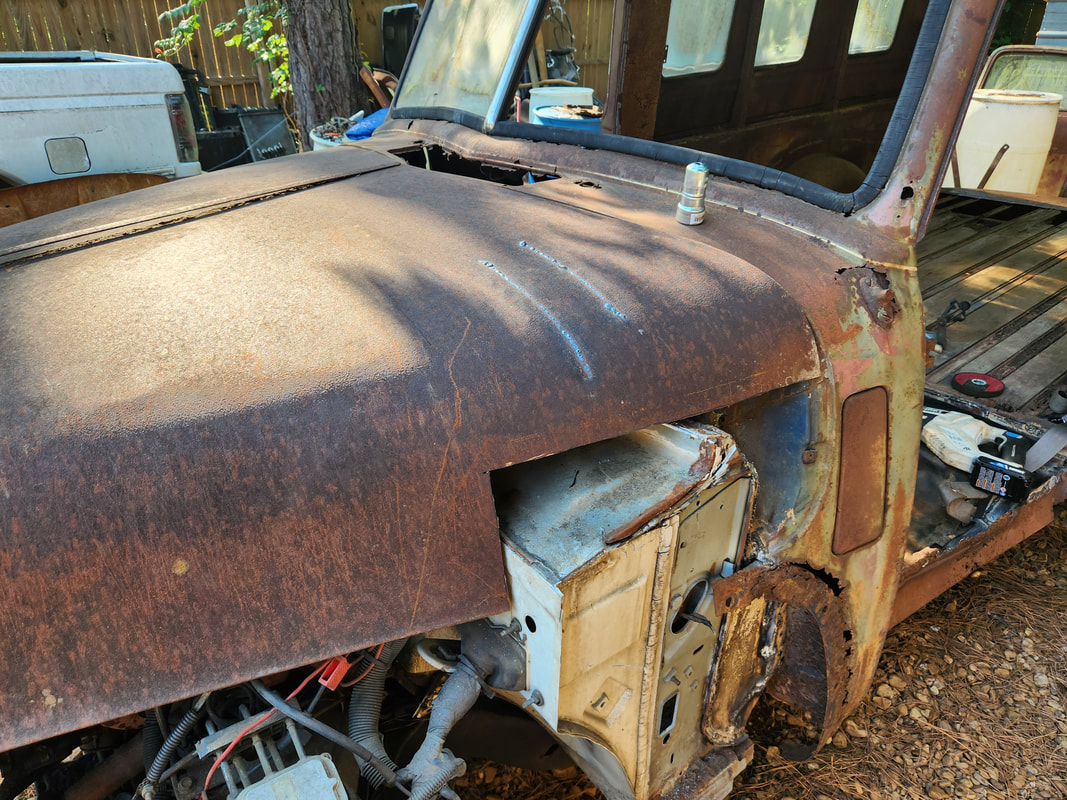
After removing the hood latch panel which gave me access to the rear of the grille, I could then proceed with removing bolts on the fenders and other hardware. In the process of removing the bolts holding the fender, I had to remove the headlight bucket to open the area up to get one bolt off. Several bolts for the fender are located all under the panel in the most inconvenient spots.
Some of the bolts for the fenders were located in the cab. Some of the bolts holding the grille and side panel to the fender were one size smaller. All of these bolts had to come out before I could remove the panels. The radiator only had a few bolts that had to come out while I just cut the rubber hoses. A large portion of the bolts removed broke due to rust. In the end, I finally got the panels off, leaving just the grille, bumper and core support to remove from the front. The next thing to remove will be the powerplant.
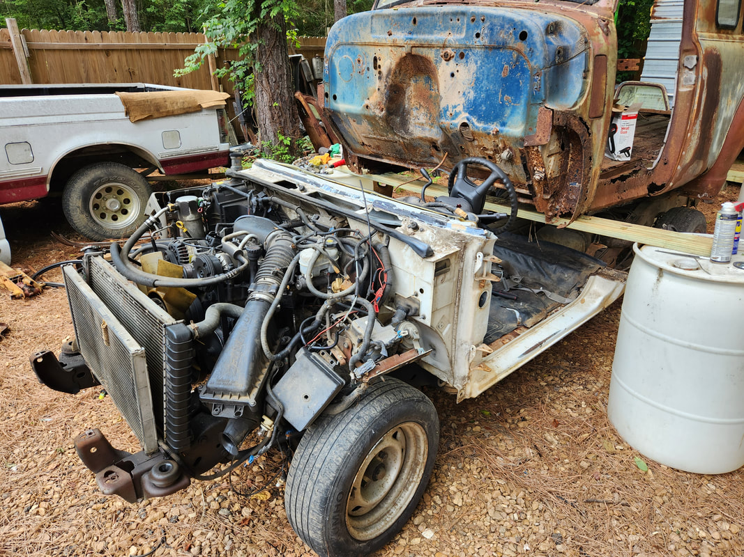
With the crane in place, I was able to remove the front mount but had to cut the rear transmission mounts to allow me to pull the powerplant free from the frame. I was able to roll the body back to free the powerplant so I could turn the crane around and load the unit onto the S10 to transport to the garage. The powerplant is pulled free after taking time to cut the transmission mounts free and rolling the body back as the powerplant was lifted up from the frame. The crane is turned around afterward and the powerplant is able to be loaded onto the S10 for transport to the garage.
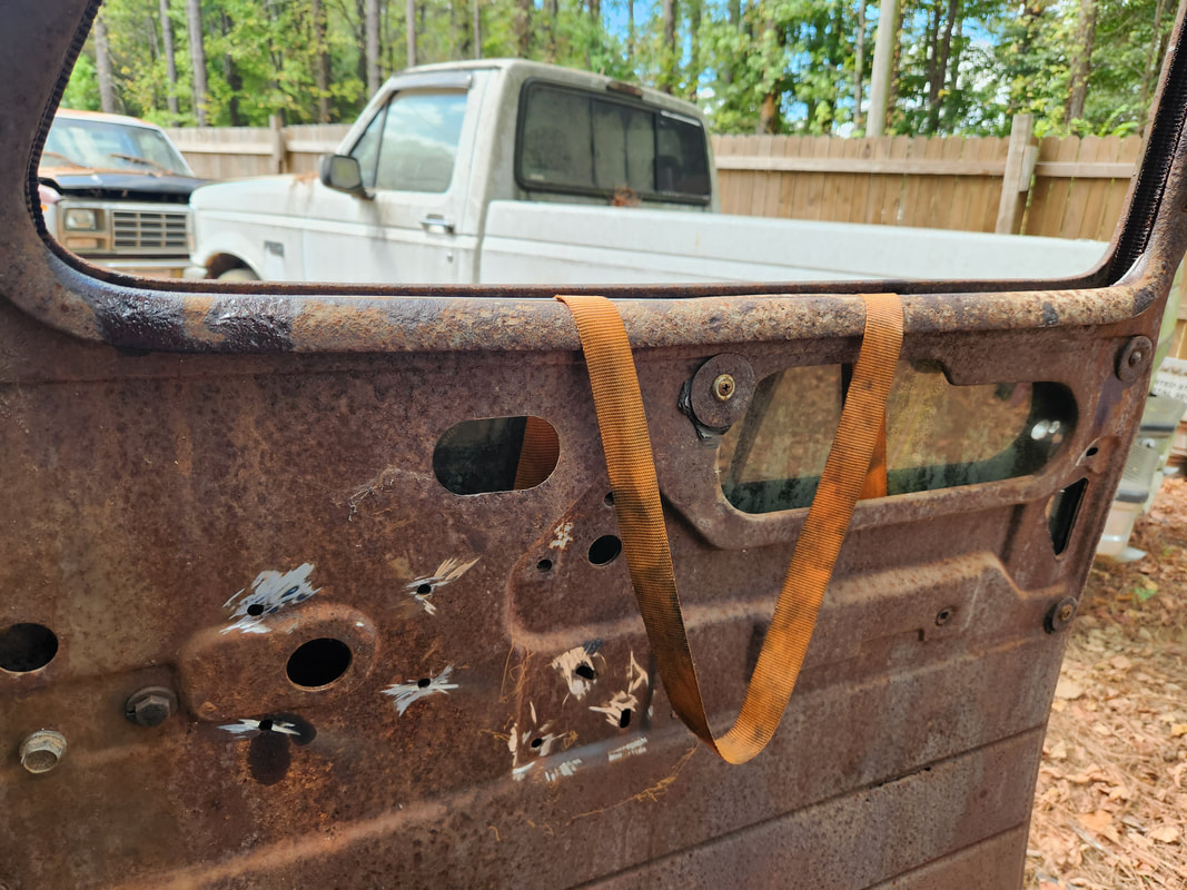
The front doors are removed. The bolts on the hinges where they bolt to the doors were cut as it will be easier to apply nuts and bolts from inside the doors versus from inside the door jamb areas if those bolts were cut free.
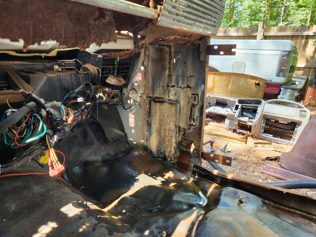
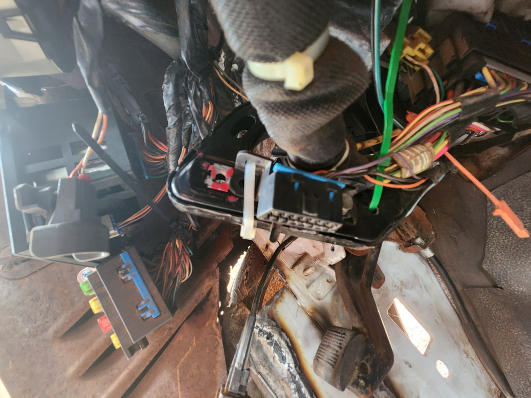
Everything under the dash was removed, the gauge cluster, wiper motor and arm assembly, wiring, switches on the dash, everything came out. Due to the steering wheel being unable to be removed, the steering column tube was cut just outside the firewall to help separate the body from the rest of the truck. Also note the left window was fully removed.
The rear doors' hinges were already rusted away, with the only thing holding them being the secondary hinges at the top. Once the doors were off the rear bumper was removed with the aid of the angle grinder on the rusty bolts and the engine crane chained into position. The body bolts were also ground free to separate the body from the frame. The fuel filler tube was the last thing to remove.
After lifting both ends of the truck carefully, I got the body supported on the boards and drums. The frame was hitched to the back of the big Tracker and pulled from under the body and relocated outside the yard to get it out of the way. For extra safety and support a third drum was placed under the middle of the rear of the body so if the board sags some, that drum will catch the body to prevent further sagging. This will be until its time to actively move the S10 chassis underneath for mating.
The added support on the front comes in the form of a large board supported on the jack and propped under the front board to prevent excess bowing. This will be removed when the S10 chassis is rolled underneath and the active mating of the two bodies begins.
The next order of business is the breakdown of the S10. All the body components will need to come off, along with the inner support components. The doors on the cab along with the seats will have to come out, as well as most of the dash. In the end, the cab will be cut down approximately 80% of the way, with the 51's body cut up to accommodate the remaining portion of the S10's cab section, which includes the steering column, which will need to be retained to be able to operate the S10's system. The engine bay components that get removed from the inner fenders will have to be accommodated somehow, as we won't be able to reuse the inner fenders from the S10, as well as the core support. Of course, in a project like this, we're really shooting from the hip every step of the way, planning things as we go along.
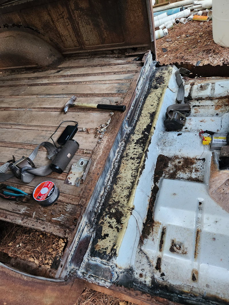
With the bed out of the way, I was able to troubleshoot the no start condition, finding the broken ground wire that more than likely went to the fuel pump wire harness.
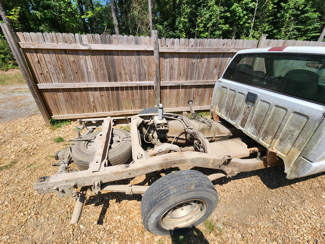
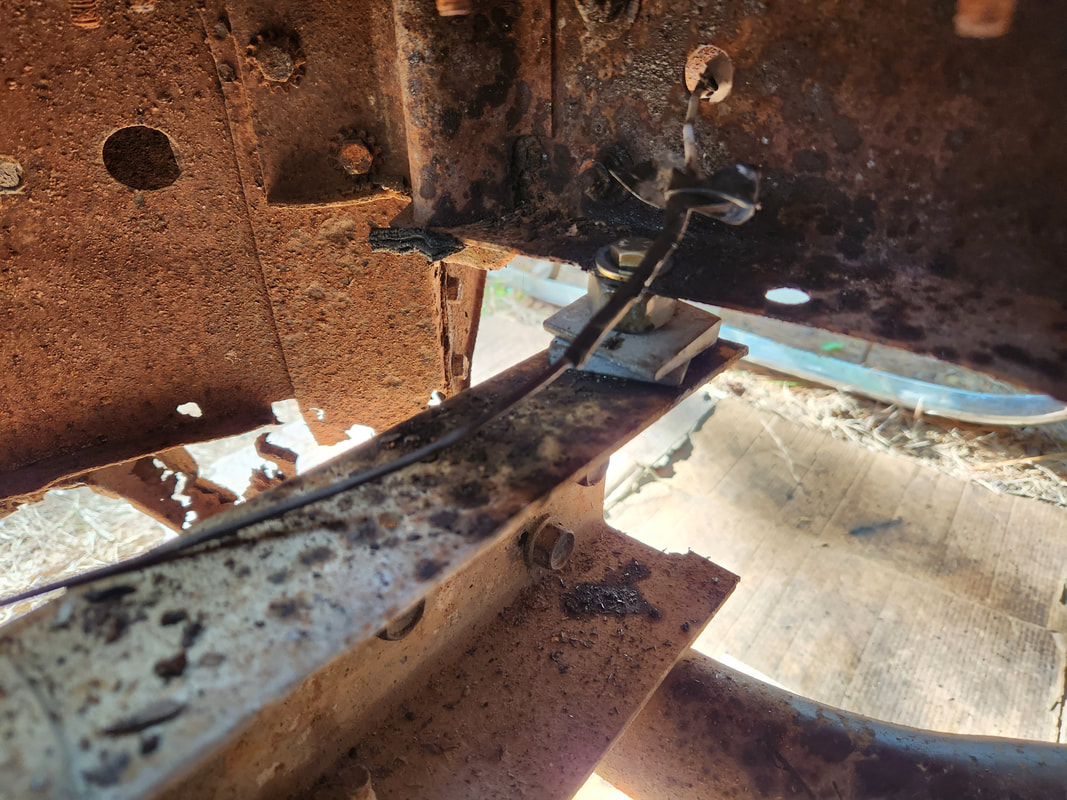
A side shot of the positioning of the rear of the S10 frame under the raised 51 body. Once the cab is cut down, further fitment can begin, where the remaining S10 chassis will be moved further under the 51 for fitment.
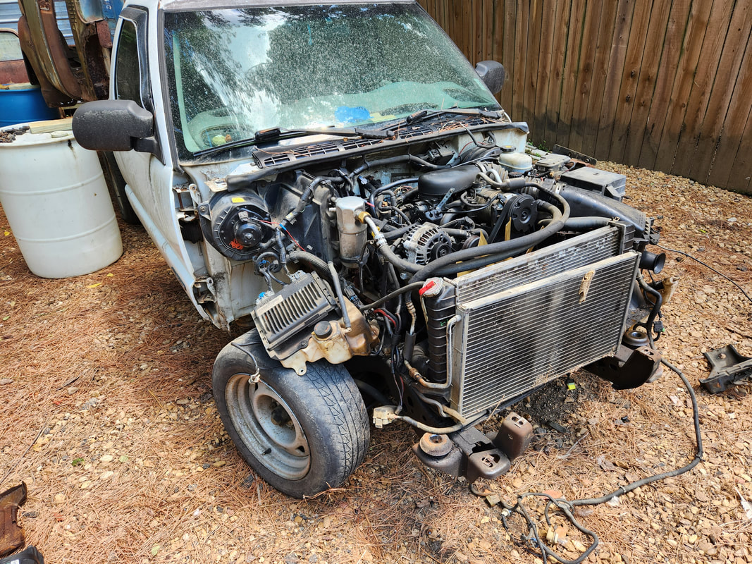
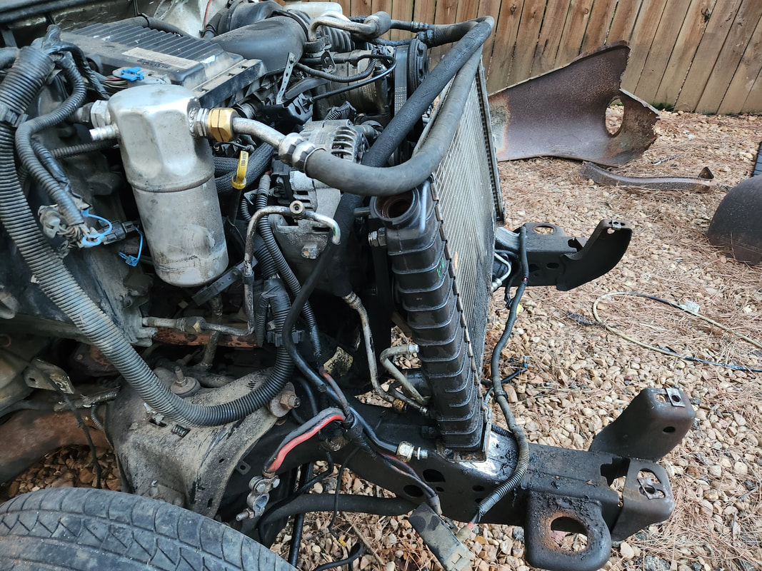
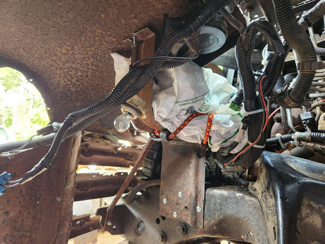
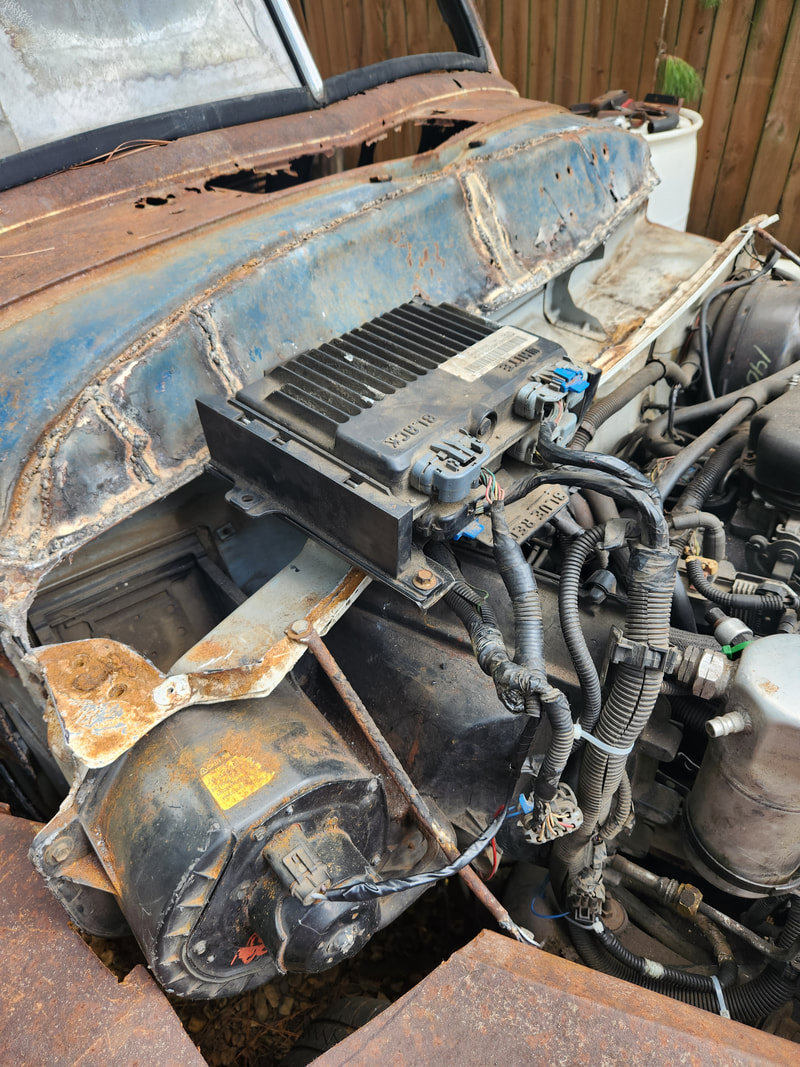
Right side shot showing the missing inner fender on the right side. The ECU is resting on the tire. A temporary battery tray would have to be fabricated to hold the battery if I want to start the truck again to move it. Some grounds will also have to be reestablished. On the left side the components that are attached to the left inner fender will have to be accommodated somehow as that panel will be removed soon. The radiator and AC condenser will also have to be temporarily supported so they don't bounce around and hit the cooling fan.
With the gauge cluster and other external components removed, I had to find all the bolts that held the dash frame in place. After a lot of studying, the bolts were located and as smaller pieces came out, it started to become obvious that the dash was coming free slowly but surely.
The gauge cluster was plugged back up as it will be reused on the build. Either I will cut out the 51's dash to accommodate the gauge cluster or mount the gauge cluster inside the dash and use the two portholes on the dash as viewers for the gauge cluster. Plexiglass would cover the holes while extra light would be used to help illuminate the gauge cluster.
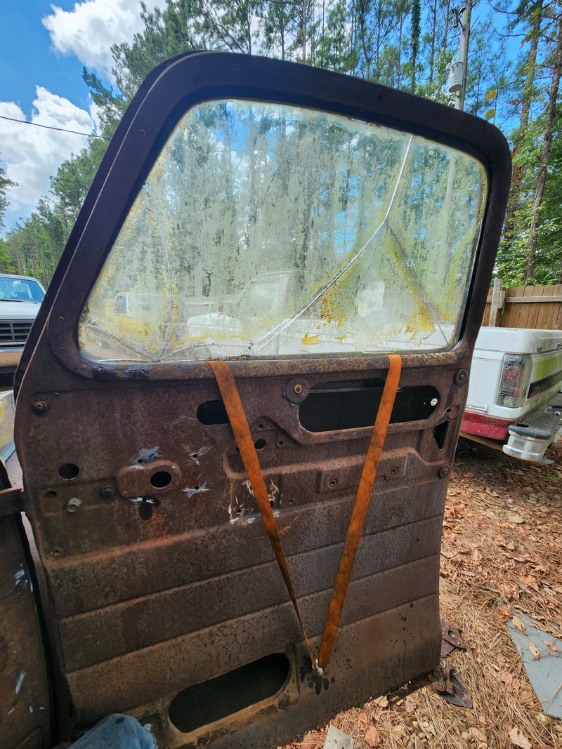
With the interior gutted, the next move was to prep the cab for chopping. I started off by removing the few panels left at rear of the cab, opening up the entirety of the rear window. This allowed me to use my heat gun and a knife and pick to scrape out enough rubber glue to allow me to remove the whole rear window intact. I tried the same thing with the windshield, but because there were already a couple small cracks present, it didn't take long before an attempt to push the window out expanded the cracks even more, making me abandon any desire to try and remove the glass in one piece. After removing the windshield out in sections, I had to scrape the glass embedded glue from around the window frame. Next, I had to knock out the hinge pins from the doors to remove the doors. Since the hinges are welded on both ends, the pins had to be knocked out to remove the doors. I was able to hammer the tips of the pins to allow the splined sections to break free, then use a flathead screwdriver at an angle to tap out the pins completely, allowing me to remove the door without incident.
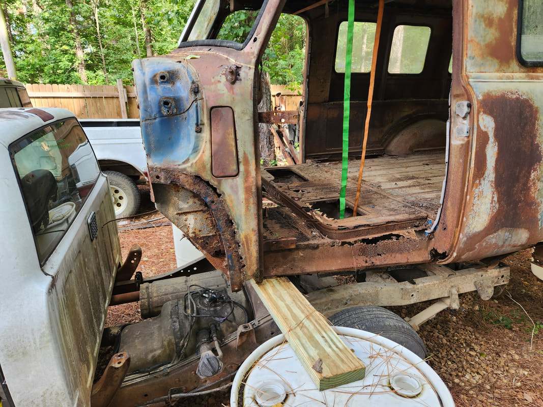
After cutting the very bottoms of the A-pillars and around the bottom rear of the cab body where the back meets the floor, we were able to roll the chassis backwards, further under the 51 body. The 51's firewall interfered with the S10's steering wheel, so we weren't able to roll the chassis all the way under the body to line everything up with each other. The 51's firewall will have to be cut out completely before this can be done.
With the S10 cut up, the next move was to start cutting into the firewall and floor of the 51 Chevy body in order to start the fitment of the body to the S10 chassis. From here, the next move was to use the engine crane to jack up the rear to remove the drums and board so I could lay the rear of the 51 body down onto the S10 frame at the rear. With the rear down, I moved the crane to the front and jacked up the front to get the drums and board out of the way. About 4" of the frame rails on both sides were cut out to allow the 51 body to be lowered down at the point where the S10's rear wheels would line up with the 51's fenders. The trailer hitch is low enough to still clear the rear of the 51 body so it's still useable.
From here I did a series of cuts around the front of the 51 body, up to and including the rest of the floor. I also chopped the rocker panels on the S10 chassis floor to line up with the 51's body frame to better fit the body over the S10 chassis. After multiple cuts and repeated lifting and lowering of the front of the body with the crane, I finally got the front of the 51 body laid down enough on the S10 chassis, over the S10's firewall section.
After multiple cuts, most of the firewall and surrounding front sheet metal on the 51 is cut away. The curved rear mounting points for the fenders are partially free floating, as the metal around these points were cut away. The hinge boxes on both sides of the S10 were cut away to narrow the width of the S10 chassis at the sides so the 51 body could be lowered over the S10 chassis. With the 51 body lowered down as far as it could go, I will have to weld in scrap metal in the open areas to help in fusing the bodies together.
Currently the dash frame of the 51 rests on the steering column of the S10. I will probably end up cutting out a portion of this dash to open up the area around the steering column, as well as accommodate the S10 gauge cluster.
|
|
|
|
|
|
|
|
|
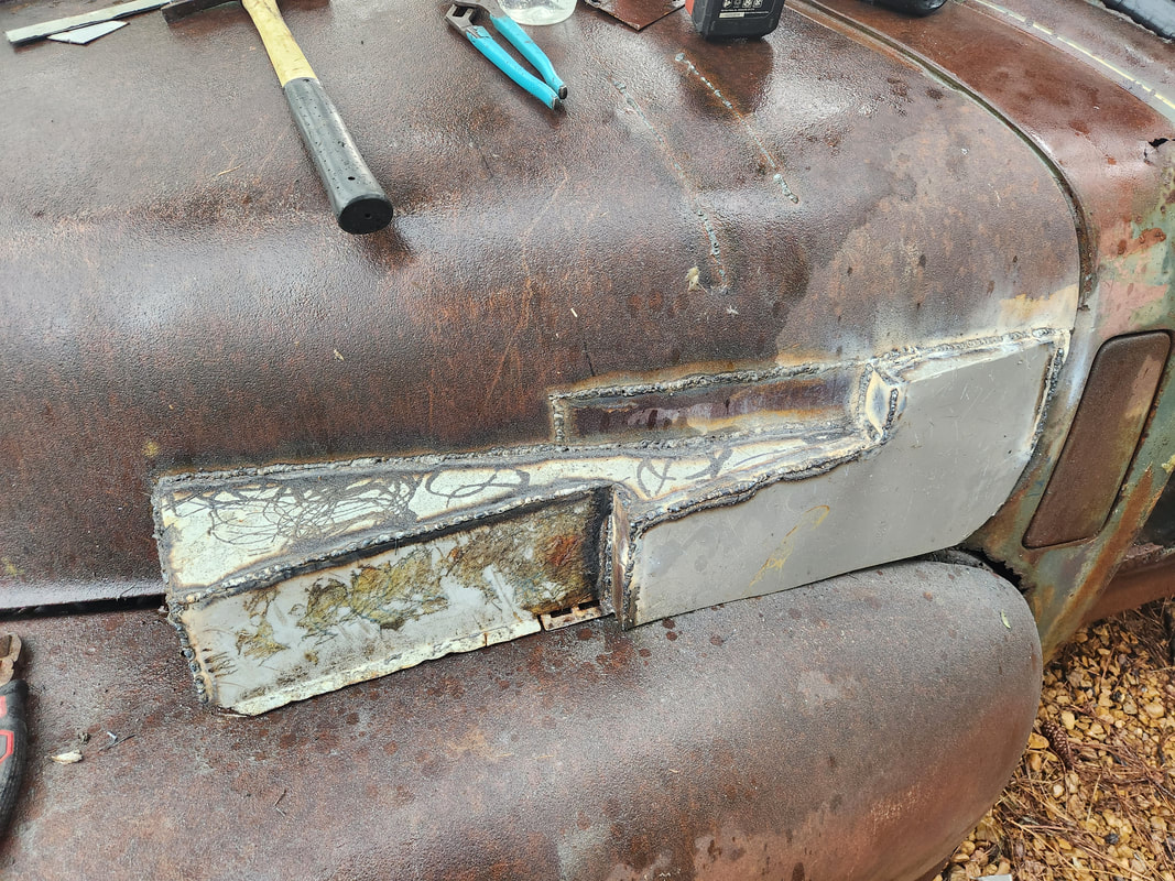
Our next move is to start the actual welding of the two bodies together. With the 51 body lined up and laid down against the S10 floor/chassis, the first target area was the point where the 51 floor meets the rear of the S10 floor. After getting this point welded up, I turned my attention to the sides, welding the side panels on the 51 to the sides of the S10 floor. From here I cut and welded multiple patch panels between the open spaces where the front of the 51 body and the S10 body are at. These panels would make up the new side panels of the finished truck and ultimately close in the cab area of the truck. Lastly, I had to close in the area at the front of the 51 body where it meets the top of the S10 firewall/wiper area. With some cutting of panels and welding in of these same panels along with extra scrap metal, I got the entire front of the 51 body closed in with the S10 body. All the way around the seams where the two bodies meet, from the sides all the way to the front top, the 51 body is now part of the S10 body. The last thing I did was secure the rear of the 51 body to the rear of the S10 frame. I had to drill new holes through the rear crossmember on the 51 body and through the ends of the S10 frame. A secondary rear mount was set up using another crossmember on the 51 body, which was originally used for holding the wood floor boards and dividing slats. Since the first third of the 51 body is fused to the S10 floor which is secured with factory body mounts, the rear mounts should be sufficient to hold the 51 body to the frame. I can install some more body mounts midway between the rear and the S10 floor, but I'll have to remove the fuel tank as this would involve me cutting out the S10 frame brackets and rewelding them to line them up with the body mounts on the 51 body.
The front of the 51's floor section still had a flap of metal remaining that served as a weld point going halfway across the rear of the S10 floor. Extra angle iron was used to attach the other half of the 51 floor with the rest of the S10 floor.
The rest of the floor is welded up with a combination of angle iron and sheet metal, closing in everything along the run of the panels and floor. This metal will help reinforce the overall body since the S10 floor is attached to the frame with factory body mounts. Multiple patch panels are welded in place to cover the gaps that were present between the front of the 51 body and the S10 hinge/door jamb panel. These panels make up the new side panels of the new cab area, closing everything in.
To close in the front of the 51 body, I cut out the rest of the firewall panel, cut that panel in two, them repositioned the two pieces at an angle to where the panels cover a large amount of the top of the S10 wiper panel. These panels were welded at this position, then extra metal was welded in to fill the gaps all around, from one end to the other. This effectively closed in the front of the cab, save for the openings like the top vent, wiper arm holes and of course the windshields.
The rear body mounts were set up by drilling a hole through the floor and into the crossmember, down into the S10 frame rail. A large nut and washers serves as a spacer between the bottom of the crossmember and the top of the S10 frame rail. A bolt is placed through the bottom part of the crossmember and through the top part of the frame rail, keeping the bolt short, instead of using an extra long bolt going all the way through the top of the floor and crossmember and down into the frame.
The secondary rear body mount was made up of another crossmember that is used for holding the wood floor boards and dividing slats. The crossmember had to be rewelded to the sides of the body due to excessive rust breaking the crossmember away. The carriage bolt holding one of the slats to the crossmember is ground out, then a hole drilled through the S10 frame directly under this hole. A piece of copper pipe is placed under the crossmember to serve as a spacer so a long bolt can fully secure the crossmember to the S10 frame. These four mounting points at the rear will ensure the rear of the 51 body is fully secured to the S10 frame.
|
|
|
|
|
|
|
|
|
|
|
|
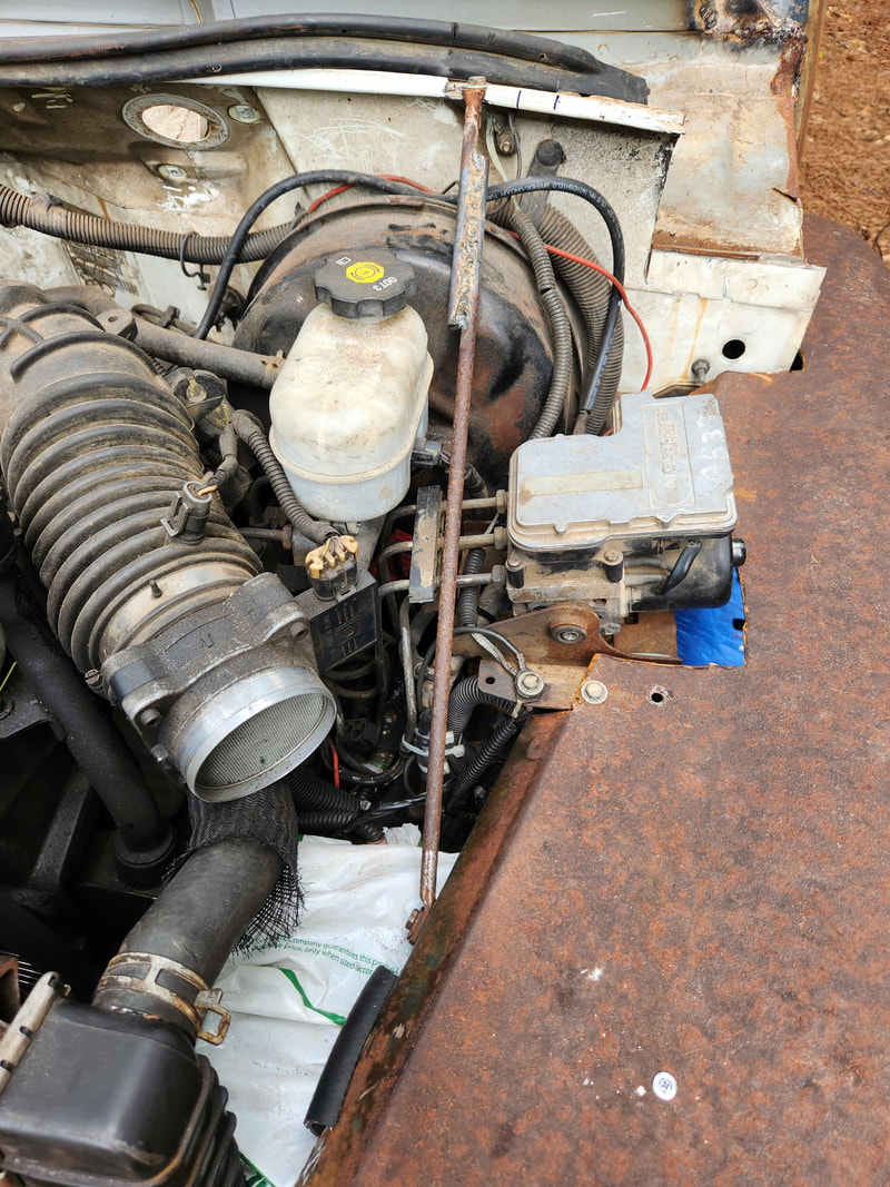
The next order of business here is assembling the front clip on the truck. Since the S10 firewall is wider than the hood on the 51, I would end up having to cut the rear of the hood to accommodate the wide portions of the S10 body that would keep the hood from being able to lay down in what would be the closed position. I took time to remove the wiper motor and arms since I will try to relocate this whole assembly in the top of the 51's panel where the old wipers went. Even with cutting out portions of the rear of the hood, I would also have to relocate the radiator and AC condenser since they are both high and wider than the front of the hood. Relocating the radiators would allow me to get the hood down to where it needs to be to close fully. I'll even have to do the same thing with the fenders to get them to fit properly. Once everything is in place, I'll end up welding some boxes out of scrap sheet metal to go on the areas of the hood that were cut out in order to fully cover the open sections of the S10 firewall and HVAC blower motor so the outside can look somewhat normal versus having parts exposed to the outside. Other components of the S10 engine bay also need to be accommodated, like the ECU and the ABS module and fuse box that were mounted on the inner fenders, which are no longer in place. These things will have to be somehow secured and away from the tires or at least shielded so water from the road can't be kicked up to wet everything down and cause damage.
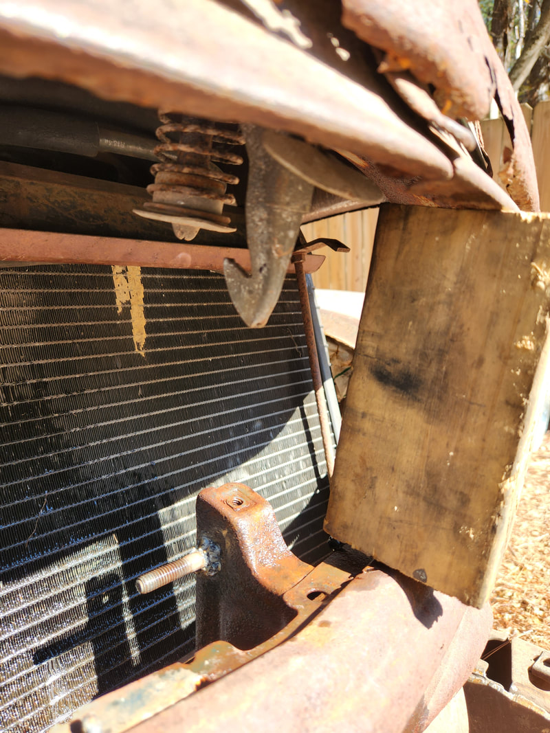
The radiator and condenser were removed and improvised brackets were made using pieces from the frame rails cut from the rear of the S10. These bracket cradles have holes that will accommodate pegs on the bottom of the radiator, where the radiator can set snug. Also the radiator will be mounted with a backwards rake to lower the radiator's position while also placing it more to the rear, thanks to the removal of the fan clutch. The radiator is in position on the cradles. Note the backward rake of the radiator. I will have to fabricate some kind of mounts that can cradle the top of the radiator as well, plus weld some extra cradle sections to accommodate the condenser. Once these are in place, I have to manipulate metal tubes that go to both radiators so they can mount in place without stressing the mounting points on the radiators.
I had to cut out a chunk of the rear of the hood to clear the very edge of the S10 firewall area, then weld the support member to maintain the rigidity of the hood. The right side was about the same with what had to be cut out, but this was to accommodate the HVAC blower motor which protruded out from where the hood would sit. I didn't have to cut all the way to the rear of the hood but I did still have to weld the structural member here just as well. I had to remove the hinges from both sides as I cut into the bases that held the hinges. This hood will have to be situated like on a race car where its secured at multiple points to hold the hood down, while opening it would involve just raising the hood and propping it with a rod, while the rear of the hood rests on the top of the firewall area.
The left side was pretty clear with the opening that was cut from the hood. It sat just right on the top of the firewall area.
A side shot showing how the radiator and condenser are cleared by the hood when its in the "closed" position.
|
|
|
|
|
|
|
|
|
|
|
|
The next order of business after getting the radiators situated in their new position is to fabricate some form of core support to hold the two pieces stationary so they won't bounce around, especially since they're closer to the rotating components on the front of the engine. I ended up using a combination of scrap components, some of which was salvaged from the old 51 hardware that was removed during the teardown. I had some other stamped steel paneling and angle iron that I used for the top of the core support and the bottom portion of the support was secured to the insides of the frame rails with nuts and bolts. Pieces of cut rubber hose were used as cushions for the top of the support. After getting the core support done I turned my attention to the right fender. I cut some of the metal out in order to fit the fender in place around the HVAC blower motor and right side of the old S10 firewall. At this moment I realized I could move the 51 body forward a few inches since the front wheels were positioned a little too far forward in the fender well. I ended up having to cut all the old welds that secured the 51 body to the S10 chassis and force the body forward enough to get the position I desired, then re-weld everything. The added bonus of all this is the idea that the intermediate S10 body mounts ended up lining up with the 51 body mounts in the middle, allowing me to add a couple more bolts to the mix to further secure the body to the chassis. With that all said and done, I went back to the front clip, getting the grille taken apart some so I can start fitting it to the front. I ended up having to cut sections out of the grille to allow the assembly to fit around the front frame rails. Even on the frame rails I had to cut off the body mounts that were for the old S10 core support as these were in the way. Once the grille was in the desired position I was able to secure the right side to the fender then set up the left fender to do the same thing. I had to cut some metal out to accommodate the left side of the firewall as well as the ABS module that would have to be set up right in the path of the fender. Once the fender was set where I wanted it, I had to do a little forcing of the fender and the left side of the grille to get the two to meet together enough to add the nuts and bolts to hold that side together. From here I was able to remove the hood as it was no longer needed for fitment of the fenders/grille. I turned my attention to the ABS module, that was on its own bracket that in its current state would be obstructive to the fender and hood. I removed and modified the bracket to allow for its attachment under the fender in the channel I cut out, reattaching the module to it so it can sit suspended in the open space of the channel on the fender. The hood needed a little more metal cut out to also accommodate the module so the box that I have to fabricate will end up be a little bit larger than anticipated, but this is fine. I also drilled a couple holes at the bottom of the grille body, through the frame rails so I can secure the grille further with nuts and bolts. I will have to add some more supporting pieces to hold the fenders stationary so they don't bounce excessively. I also have to secure the fuse box and ECU and all the loose wiring that is present.
Before adding the new core support, old radiator hose was cut into short pieces and split lengthwise to fit around the tops of the condenser and radiator to serve as cushions so the core support metal won't chafe the tops of either radiator. The new core support is secured over the radiator and condenser with the bottom ends bolted in place to the inner frame rails. Holes had to be drilled on the frame rails to accommodate the nuts and bolts. The large size of the frame rails allowed for easy reach inside to apply the bolts. Note how the rods were cut and rewelded to shorten them near the bottom.
Because multiple spots on the grille assembly had to be cut out to fit the assembly around the frame rails, new support metal needed to be welded in place closer to the center to support the overall grille. Note the open spaces on the ends of the grille
After test fitting the fender and hood, channels were cut out from the fender to accommodate the HVAC blower motor. The grille is fully installed along with both fenders here. The left fender had a small amount of metal cut to accommodate the ABS module as well as the end of the firewall. The fenders are both bolted to the ends of the grille and lined up as desired. Note how far back the grille sits on the fronts of the frame rails. Only reason the ends of the frame rails weren't cut away is to allow for some material to be able to attach a front bumper without the brackets reaching too far back where they will interfere with the sway bar and other suspension components.
I had to fabricate a bracket for the ABS module using the old bracket. After cutting and welding the bracket together where it could bolt to the fender with one bolt on either side of the bracket, I was able to secure the module as desired. As for the fuse box, I had to fabricate a whole new bracket/mount that attached to the bottom of the fender with a self tapping screw and to the frame with more self tapping screws. The bracket would cradle the fuse box. I did cover the fuse box with a plastic sack to protect it from spray from the tire if driving in the rain. Bungee cords further held the fuse box in the cradled bracket. On the fenders I welded up rods with bolt loops on both ends to attach between the fender and the S10 firewall to hold the fenders steady, since there would be no inner fenders to help stiffen the fenders as on the original trucks. With the ABS module done, I turned my attention to the ECU. I had to fabricate a couple of brackets from some old component brackets pulled from the S10 engine bay during that tear down. I had to test fit the ECU mount to get the spacing right then weld the two brackets down in the space on the top of the S10 firewall where the wiper panel used to sit. I was able to bolt down the ECU mount at the front points of the assembly, using one of the bolts that came with the bracket and a nut/bolt on the other bracket. At the rear of the mount I used a self tapping screw to secure the piece. From here I moved on to making the boxes for the hood. The right side was fairly easy as it was just a simple straight box going around the HVAC blower. The left side was a little more involved as it reached from the rear of the hood to about 2/3 the way along the hood, past where the ABS module sits. I had to cut pieces of sheet metal and bend tabs that would make welding the following pieces of sheet metal to the former piece easier. Once the first main piece was in place, things came together rather quickly, resulting in an oddly shaped box covering the opening around the ABS module and side of the firewall that was sticking out.
A shot of the fabricated fuse box bracket showing where it attaches to the underside of the fender and to the side of the frame rail with self tapping screws. Note the plastic sack covering the box and the bungee cords holding it in place.
A shot of the left side showing the connecting rod holding the fender to the firewall, along with the ABS module that is secured with its fabricated bracket. With no inner fender in place to support the fender, this rod, made from a support rod pulled from the old 51 chevy hardware, was modified to fit as shown.
The ECU mount is bolted to the two bracket pieces via a stock bolt on one side and a nut/bolt on the other side. The back side uses a self tapping screw to hold that end of the mount in place. The ECU is snapped in place on the mount. The hood had to be test fitted to verify the hood would sit properly over the ECU without being obstructed by said ECU.
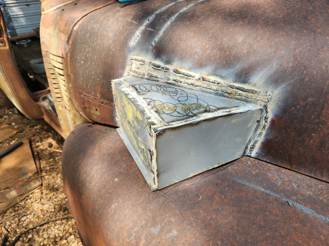
The right side box is welded in place over the opening that was cut out of the hood and fender. This box was easy to fabricate since all that was accommodated was the HVAC blower motor.
The left side box was a little more involved due to the different sections of the hood and fender that were cut out to accommodate the ABS module and firewall. After getting the first piece of sheet metal cut out and welded to the top, the other pieces "fell" in place. Extra tabs were bent on the pieces to allow for overlap that would make for a better welding between the two pieces of sheet metal. This box covers the large area ranging from the rear of the hood to about 2/3 the way up to the front of the hood, with multiple right angles in the box.
The hood with its boxes in place is set back down over the engine bay of the truck, covering everything as intended. Due to the warpage of the hood and fenders after cutting out the metal that I did cut out, the hood has gaps around the edges where it meets the fenders, as well as the firewall. There is added distortion on the body from lifting it with the engine crane just under the firewall, plus there is a large dent on the right side just under the A-pillar, all contributing to the distortion that has gaps in place between the hood/fenders.
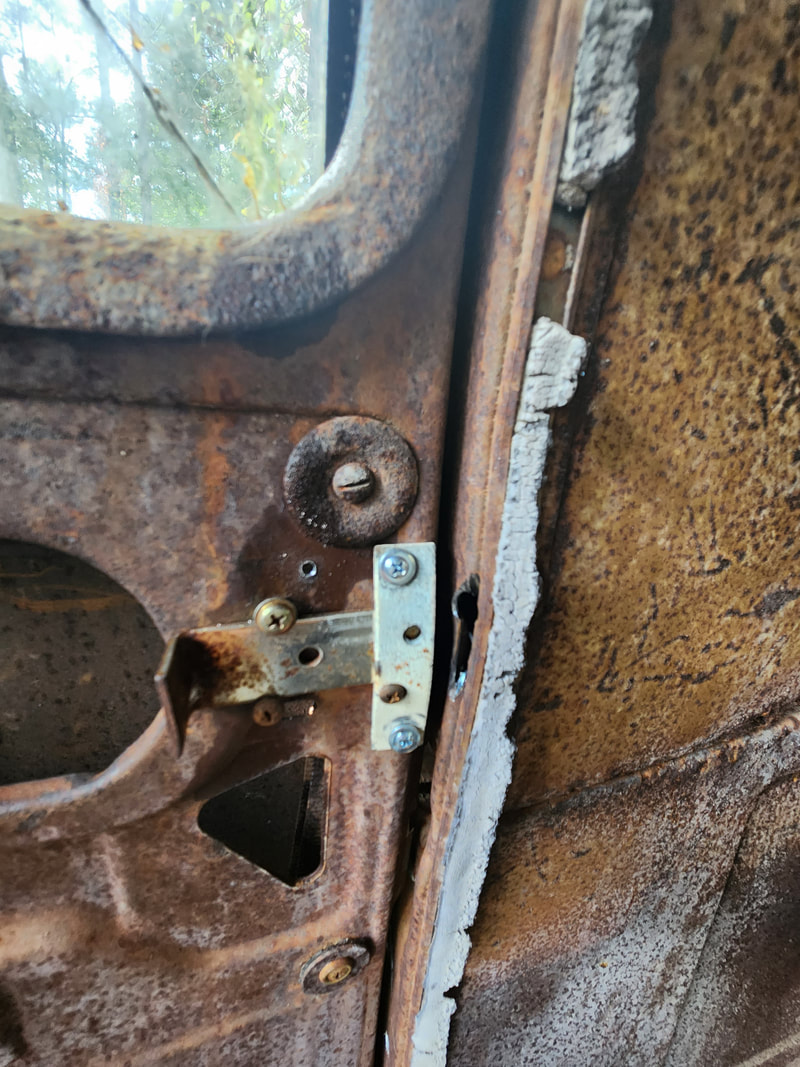
The next move is installing the doors. The side doors would be simple as its just a matter of putting the doors on the hinge ends and bolting them down. The threads used on these doors are a finer thread than the normal coarse thread of most standard sized bolts. Unfortunately, the bolts pulled from the doors were too old and rusty to reuse. I was able to find four bolts of this fine thread that I could use, with two going on each of the top hinges. The bottom hinges were in a spot where an opening on the doors allowed me to put long bolts in place with nuts behind them. Once the side doors were in place and straight, I turned my attention to the rear doors. This would be interesting as the hinges, or what remains of them, were of no use due to excessive rust. The areas of the body were also rusted heavily, making it where installing the stock hinges might make the body deteriorate more in these areas, causing the doors to break free. The only other alternative at this moment was to use some standard door hinges. To test the theory, I secured them with self tapping screws and sheet metal screws to verify the doors would open and close properly with the hinges in place. With that all said and done, I can add some reinforcement later or use longer bolts with nuts to hold the hinges in place.
The passenger door is in place, in the closed position. This door doesn't have any latches or handles so it closes loosely. A latch will have to be fabricated to allow the door to be secured on the outside without being too tacky. The driver's side door still has the old latching hardware but its all worn out where none of it works, so that hardware would have to be removed and replaced with new hardware to restore normal operation to the doors.
Note the rusted out openings on the doors and the body around the door frame/jamb area. These standard hinges are secured in place with self tapping screws and short sheet metal screws to hold them in place to verify the door's opening and closing with the hinges. I will have to drill holes all the way through the subframe under the body to allow for the placement of longer bolts that can be secured from the inside with nuts and washers. Some reinforcement metal will probably need to be welded in place for added support. The doors are setting flush on the body with the hinges. As with the side doors, some form of latching will need to be set up to secure these doors too. Perhaps later on some patching will be done to cover up some of the excessive rust.
Going to the inside of the truck, I have to remove the dash in order to refit it more recessed under the windshield area to it will clear the steering column, which also has to be remounted. I trimmed the edges of the dash panel afterward and fit the piece in place, securing the panel with self tapping screws on the left and right edges. From there I welded a couple angle braces to the body and one more in the middle where the outside air vent was. More self tapping screws secure the dash panel to the angle braces. The next order of business was fitting the gauge cluster. I cut out the left panel in the shape of the gauge cluster then marked drill points for the two top mounting holes on the gauge cluster. At first I tried mounting the gauge cluster flush with the dash panel but the lower right side of the gauge cluster pressed outward against the shifter, not allowing it to lock in place. I mounted the two long 1/4" bolts to the dash panel with nuts on the inside, making two studs. I then added two more nuts with washers about 3/4" from the tip of the bolts. This allowed the gauge cluster to sit on the studs, recessed inside the dash a little bit, and away from the shifter. I will have to add some support rods to the bottom of the dash panel and even the gauge cluster to further secure all so nothing bounces around when the truck is running and vibrating.
With the aid of a couple boards to hold the dash in place, I was able to line up the panel and secure it with self tapping screws on either side, from the inside of the dash at the left and right. Looking on the upper left side the small angle brace is visible that was welded to the body, then anchored to the dash panel with a self tapping screw. The third angle brace used is welded to the outside vent opening just in front of the middle post on the windshield and anchored to the top of the dash panel with self tapping screws.
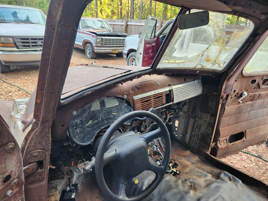
The dash panel and gauge cluster are mounted in place, along with the steering column. I will have to add some form of supporting rods on the bottom of the dash to hold the piece tight so it doesn't vibrate when the truck is running/driving. In order to install the gauge cluster a pattern was traced in the left side and cut out to fit the gauge cluster. Two long bolts were secured with nuts to create studs while more nuts and washers used to anchor the gauge cluster to the studs, recessed inside the dash panel to mount it forward of the steering column where it will clear the shifter. As can be seen, the shifter is barely touching the bottom right corner of the gauge cluster after this mounting arrangement.
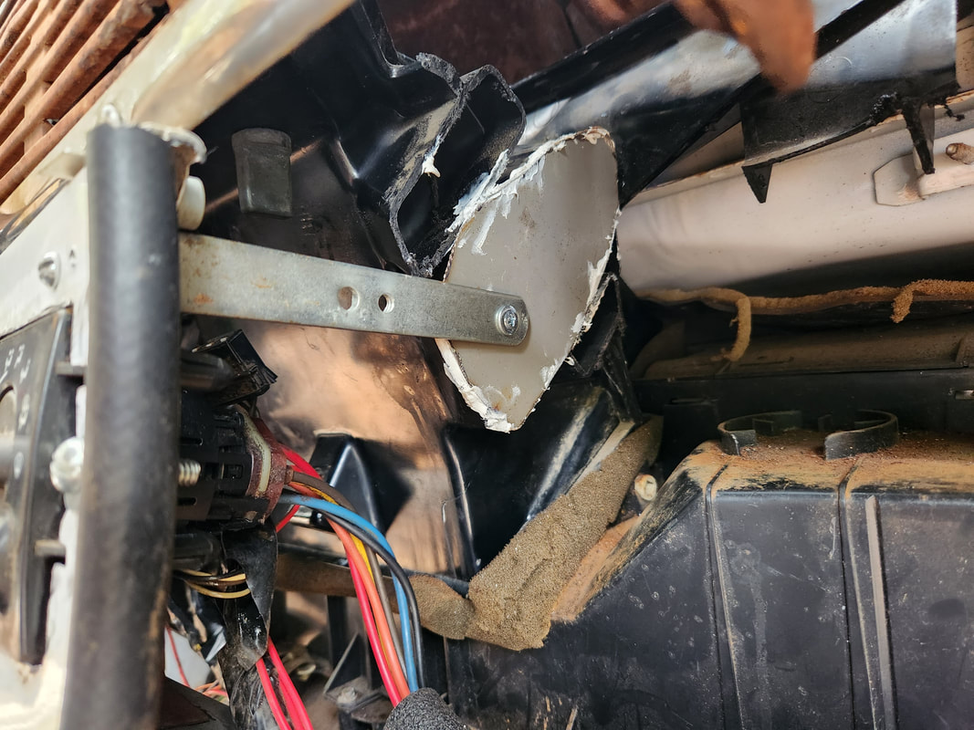
The next order of business is setting up the HVAC ductwork. The original ductwork was too wide to fit in place so the sides were chopped off, leaving the center section with the chest level vent and defrost vents. I had to plug the openings that were created as a result. This was done using some scrap sheet metal. Once this was done I was able to wedge the ductwork under the dash and set it on top of the lower portion of ductwork. I will have to figure out how to accommodate the defrost vents as the current ones are situated forward of the windshield. I might tap into the chest vent duct and add some tubes to direct some of the air to the windshield and just have a simple fixed always on setup where air is blowing through the defrost and chest vent. I could also add a crude panel that can be moved to direct air out the vent and upward to the windshield. We'll see. I also took a moment to use some angle braces to hang the headlight switch and fuse box on the left side, as well as bolt the OBD2 port to a supporting member under the steering column. There's still plenty to do under the dash.
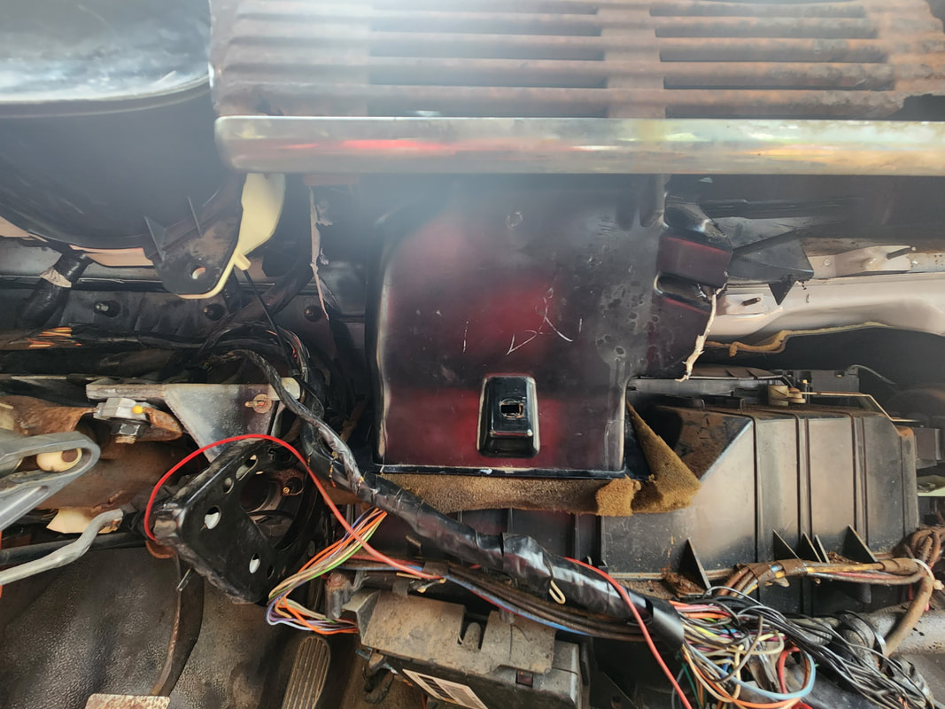
Templates were cut from cardboard to take the shape of the openings, then the same templates cut with the cardboard out of sheet metal. These patches were glued to the openings on the sides of the HVAC ductwork. The HVAC ductwork is wedged under the dash into place on top of the lower ductwork. The chest level vent sits nicely behind the original trim panel, unseen. The defrost vents are far forward of the windshield and will not be able to be used in their current state.
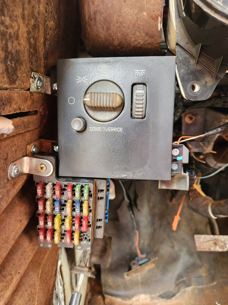
Angle braces are used to secure the left side of the headlight switch panel to the left side of the truck body. The upper right mounting tab is hooked to a peg on the lower left mount on the gauge panel. The fuse box has a single mounting tab bolted to a single angle brace. A zip tie is used to hold the wire bundle behind the box to one of the louvres on the body panel. A light fixture is bolted to the lower right mounting tab on the headlight switch panel.
The OBD2 port is bolted to the supporting member under the steering column where the original S10 dash was secured to. A zip tie holds the other mounting hole on the port to the member.
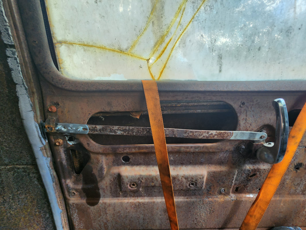
The next thing I took care of was make a center panel to hold the HVAC control panel and radio. This was made from a piece of sheet metal cut from a dryer door. I traced and cut the holes out for the two items, securing everything in place with nuts and bolts. There was still a lip on the piece of sheet metal from the original door that I was able to use as an anchor point to secure the panel at the bottom with self tapping screws. I used angle braces to hold the top of the panel to the dash by hooking one brace under the trim panel and the other with a hole drilled through the trim piece. The panel sits close to the HVAC ductwork so the old CD radio had to come out and will have to be replaced with a media player that is lower profile. Afterward, I also took a moment to install the old S10 seats back on the floor where they were originally mounted. Moving on from there, I had to take some time to cut out the old window regulators from the doors. Since the driver's side window was already down, once I cut out the bolts I was able to remove the whole regulator without having to cut any part of the unit. The passenger side window regulator had to be cut since it was in the raised position and frozen, making it unable to be worked out of the slots on the window base. The driver's side door still had the latch and lever mechanisms and as such, had to have its bolts drilled out. I did leave the interior lever and bar in place, as I could use those components in the construction of an improvised latch and release mechanism. I will have to figure out how to raise and lower the windows now that they're freed up and able to be pulled up and down, despite the fact that they can't be moved evenly in the tracks.
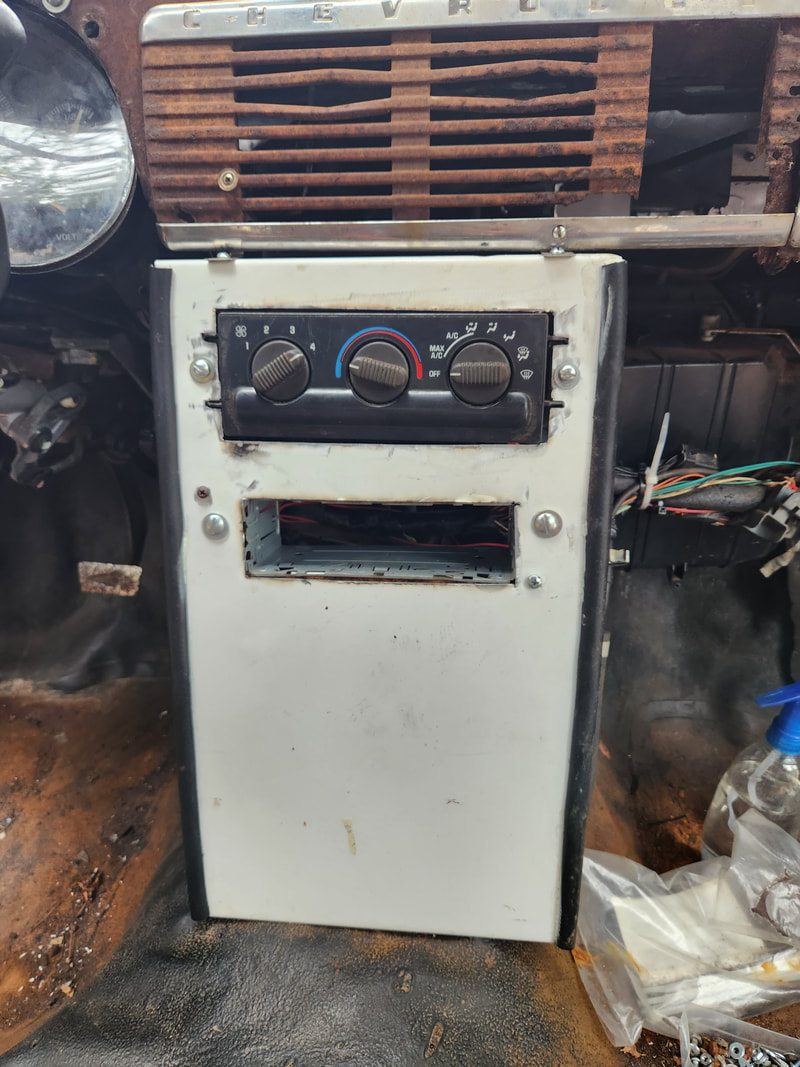
The center panel made from a dryer door. I have the HVAC control panel and radio mount in place. Note the top of the panel with the angle braces used to secure the panel. The left panel is hooked between the bottom dash trim piece and the rusted metal behind it while the right brace is secured with a nut and bolt through a hole drilled in the trim piece since the metal behind it was rusted away at that point. Also two lengths of rubber hose are cut and split to fit around the sharp edges of the panel.
An extra brace is used to hold the center panel near the top in order to keep the panel from flexing too much. A bolt is secured on the opposite side for the same purpose, maintaining rigidity.
The seats that were used in the S10 were mounted back in place on the original mounting points.
To address raising and lowering of the windows and latching the doors, I would have to come up with something pretty bootleg by most standards. Using an idea I seen online for the windows, I bolted a piece of ratchet strap material to the bases of the windows through drilled holes, using small nuts and bolts. The strap comes up through the top of the door where the window can be pulled up and down by the strap, with the two anchor points allowing the user to keep the window level as its raised or lowered. At the bottom of the door a bolt is installed to hook the strap to hold the window in the raised position. As for the latches, the driver's side door makes use of the interior lever and bar to make a sliding latch that holds the door closed. On the passenger side I had to use some metal braces to fabricate a cruds sliding latch to do the same thing. As for the outside, simple sliding latches like what's used on a gate or bathroom stall are used to latch the doors from the outside.
Next order of business is getting power back on the truck. I had to relocate the battery to the interior since there's no room under the hood. I used an aluminum coupling to couple the end of the positive cable to a length of amplifier power cable, which is then run along the frame rail to a spot just behind the passenger seat. A piece of rubber hose covers the aluminum coupling to keep it from shorting on any metal. I had to weld in a sheet metal patch over the opening in the floor. The negative cable is secured directly to the frame just under the floor. With the floor in place and the cables in place, I hooked the battery up and put power back on the truck, starting the engine up for a brief time. From here I addressed the interior lights. I had to do a partial rewire on the two floor lights, as there was no ground to the fixtures. The dome override switch didn't work so I installed another switch in the dash that would serve as the switched ground. With those lights working, I installed an LED light strip around the top of the interior, wiring that in with the floor lights so all these lights come on at the same time.
I also installed the homemade LED array that would serve as the dome light by attaching it to the old headliner support member and wiring it in with the strip lights.
To raise/lower the windows, a length of old ratchet strap material is bolted to the window base at two points then fed through the top of the door. The strap is pulled up to pull the window up and lowered to lower the window down.
In the raised position the strap is hooked to a carriage bolt secured at the bottom of the door with two nuts so it can stick out an inch. Pulling on the strap at the two anchor points allows the window to be raised somewhat evenly so it doesn't shift in the tracks.
The driver's door latch is made using the old lever/bar from the old mechanism. A piece of brace used for hanging light fixtures is bolted to the end of the bar and secured with a conduit strap that's bent to make it fit close enough to the bar to keep it from shifting around. A coin slot is cut in the door frame to accept the end of the bar, completing the sliding latch assembly.
The passenger side door latch is made with two braces. One brace is slightly bent and secured with three screws, providing a small opening for the other brace to pass through. Two more screws are in place to serve as extra guides for the other brace, which is the sliding latch. Another coin slot is cut in the door frame to accept the brace/latch.
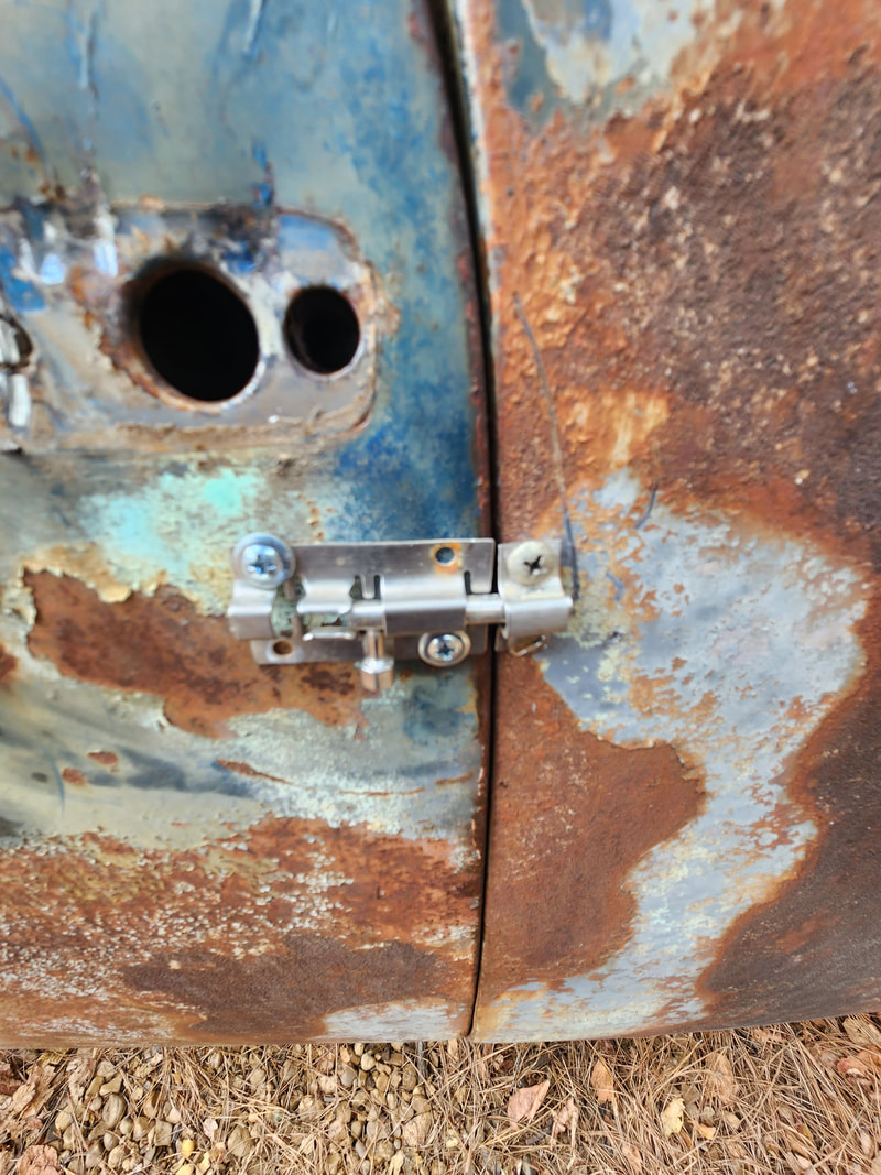
Simple sliding latches, such as those used on gates or bathroom stall doors are used for latching the doors from the outside.
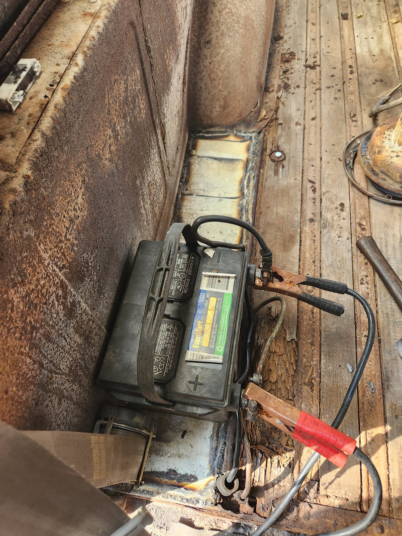
A large opening in the floor on the right side had to be covered up since the wood panels and metal dividers are rotted away. A large piece of sheet metal salvaged from the old S10 cab is cut and welded in place over the opening to cover this up. The positive cable is routed along the frame and up through an opening where excessive rust prevented complete welding over. The negative cable is bolted directly to the frame just under the floor. Both cables have hose over them where they pass through the floor to protect them from chafing. The cables are secured to the battery which itself is loosely sitting on the floor. Later a plastic battery box will be used to hold the battery in place on the floor.
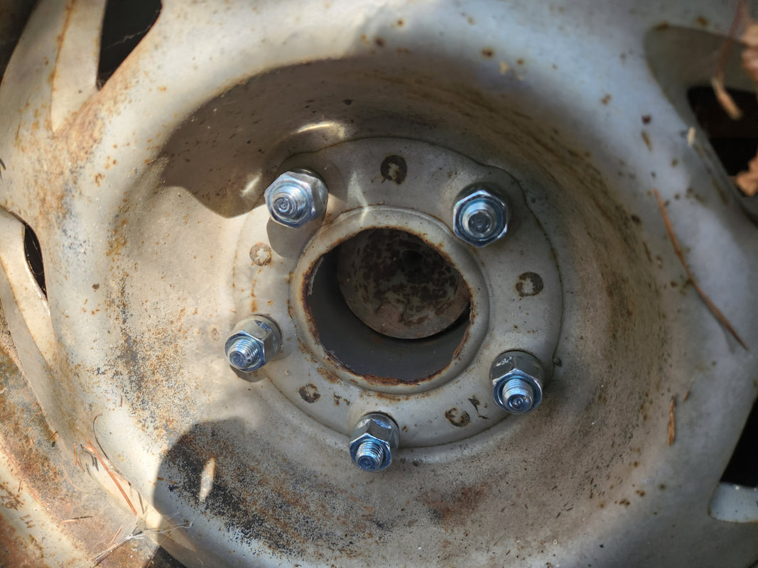
Wheel spacers were added to the rear wheels since they were scraping on the inner fender wells. The recessed wheel hub shows the spacer in place.
Since the dome override switch wasn't working for the floor lights, I had to cut the ground wires from both fixtures and route them to this toggle switch, which was then hooked up to a ground point.
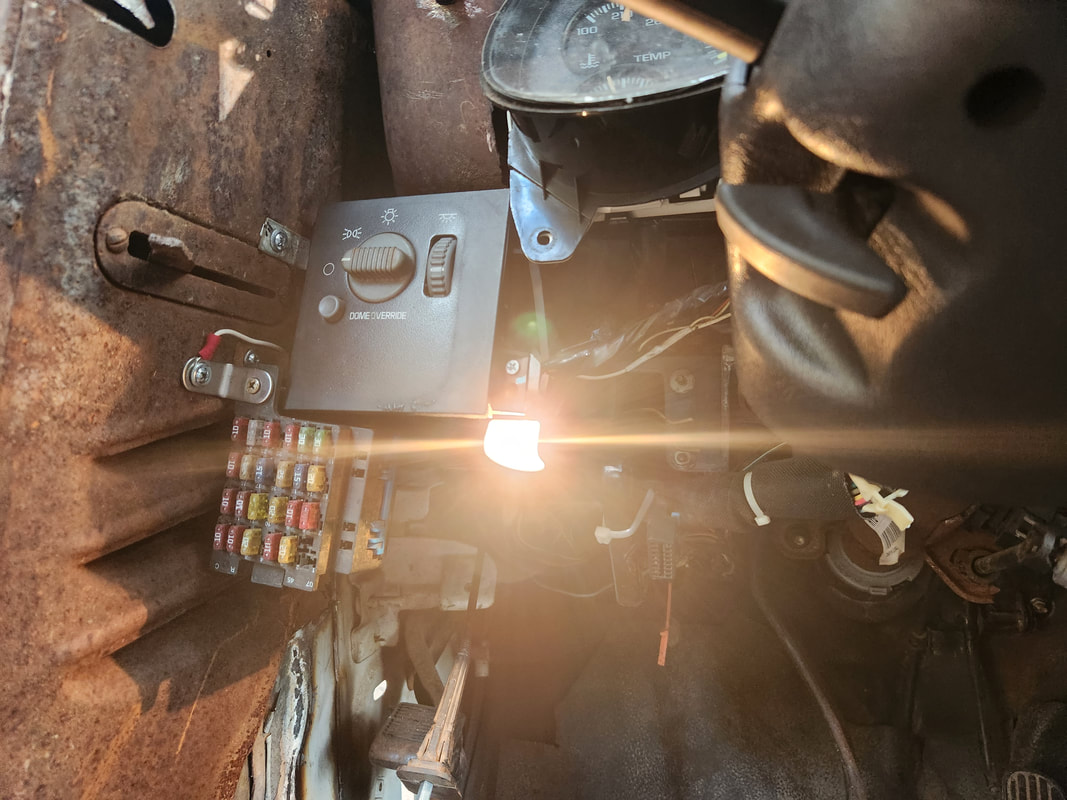
The floor lights work off the switch by itself, later I'll add door switches which will be wired as switched grounds, parallel with the toggle switch. Note the white wire hooked to the brace holding the fuse box, this is the ground wire coming from the toggle switch. The passenger light had to have wire added to the power line to allow it to stretch over to the right side panel where it's bolted in place.
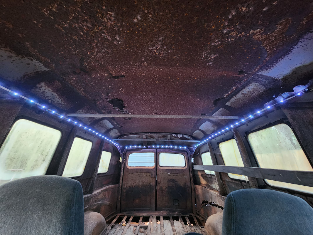
Wired in parallel with the floor lights is this modified LED strip light that's routed around the top of the interior. A 2 conductor cable is secured to the side just behind the door frame and routed down to the floor and under the floor mat. The cable comes up along the firewall where its zip tied to the existing wire harness and spliced into the left floor light to come on at the same time. The strip light is routed to the back on the driver's side, around the back and along the passenger side to the front, bathing the interior in cool white LED light.
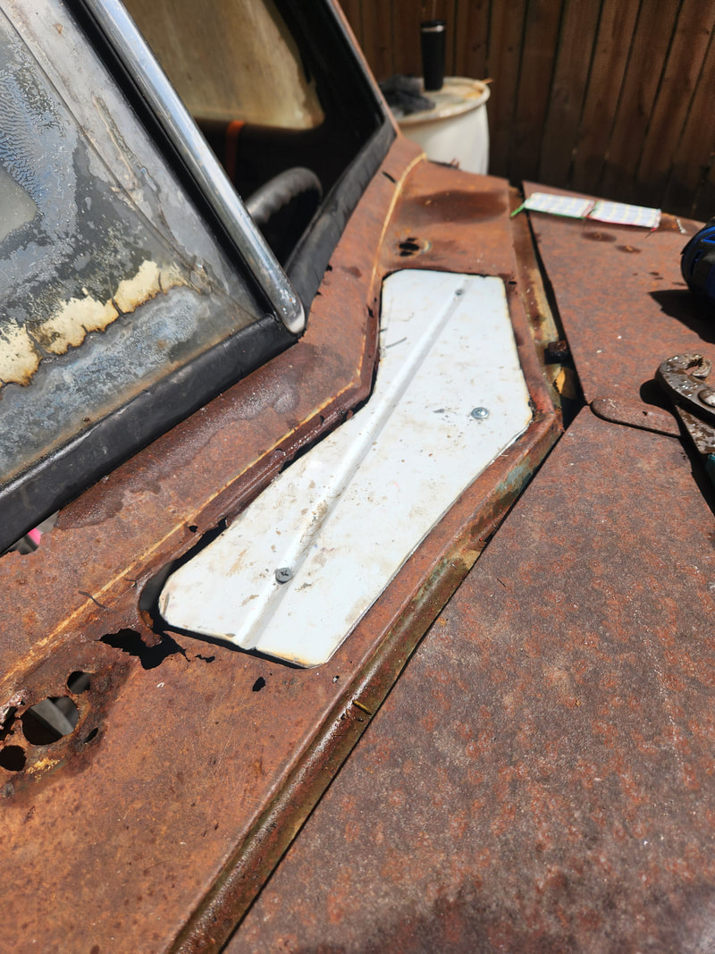
On a side note, I had to cover this old vent hole by cutting a template from cardboard then using that to cut a patch from some old S10 sheet metal. Three self tapping screws are used to secure the patch to the dash underneath. Some adhesive will need to be added as a caulk around the gaps to seal this area.
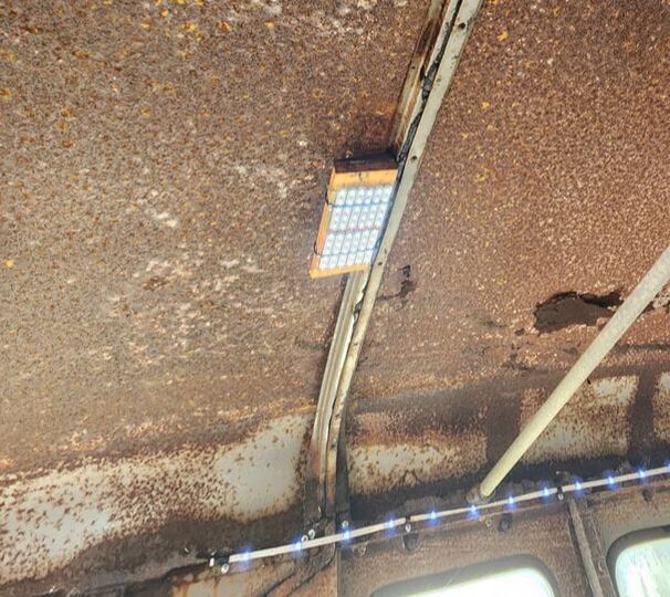
This LED array is made from the circuit board salvaged from an old T8 LED bulb. The pieces were wired together in a series/parallel circuit to allow the array to work off 12v. Two holes are drilled on the metal member to allow for the use of zip ties to hold the array in place on the wood board. The support member is hung in place with the sheet metal tabs serving as anchor points with self tapping screws being used to secure the ends to the upper body. A pair of wires were soldered to the ends on the LED array and tucked in the channel of the support member and routed to the driver's side where the wires come out and are spliced in with the wiring for the LED strip light. Note the array's illumination with the strip lights.
With the work pretty much done on the inside, I just had to secure the parking brake cable. With an angle brace and zip ties, I was able to get that one component taken care of. Next on the menu was the pair of side view mirrors getting mounted on the doors. From there I moved outside the truck, working with the front lights. I used the original headlight buckets but removed the old wiring. I still used the grommets on the buckets for the new wiring. I installed a pair of H4 7" light housings so I can use LED bulbs later on. After figuring out a way around the either/or style of headlights on the S10 wiring, I had the single H4 bulbs working as intended. After getting the headlights addressed I removed the original turn signal lights which were rusted and useless. They were replaced with some aftermarket LED fixtures that were approximately the same size as the old fixtures. These were wired into the S10 wiring for the original turn signal light sockets. From there I installed a pair of 12" rad fans on the inside of the radiator and wired them to an automotive relay which gets its coil power from a switched 12v line in the cab. Moving to the rear I installed the pair of bullet style pedestal taillights, originally used for motorcycles. I had to weld a couple of angle iron mounts on the sides by the rear door hinges to accommodate the light fixtures, routing the wires through holes in the body just below the angle iron mounts. A past electrical gremlin on the S10 brake line wiring came back to bite me in the ass so I'll have to address that before I can fully complete the taillight installation and move on to the final things before I can test drive this thing.
Mounting the parking brake cable was a simple matter of taking an angle brace and cutting a notch into it to accommodate the cable body. The angle brace was secured with self tapping screws and the cable further secured with zip ties.
These mirrors, more geared for use on cars with a more horizontal surface on the door to mount it, had to be cocked at a sharp angle to get the mirror to be level while the base was at a sharp angle. Mouning was a simple matter of drilling a couple holes in the door and screwing the base down while securing the mirror body to the base with a single screw. Later I will more than likely update to something more geared for use on trucks.
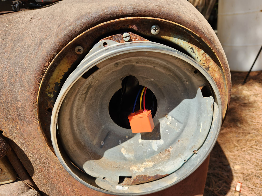
The original wiring in the headlight buckets had to be removed but the grommets were saved. The new wiring will be able to safely pass through the body with the grommets. The headlight bucket is secured to the fender with the new H4 plug wired up to the S10 wiring. The ground from the high beam plug was wired into switched ground on the H4 plug for the high beam. Even though the S10 lights are an either/or type system, I was able to get the single bulb to function properly with the S10's regular selector lever.
All front lights are in place and ready to go on the truck. Original headlight rings are used to hold the H4 housings in place and angle braces hold the signal lights in place. Mounting bolts for the fender to the grille hold one of the angle braces on each signal light while a small nut and bolt hold the other angle brace to the grille body itself.
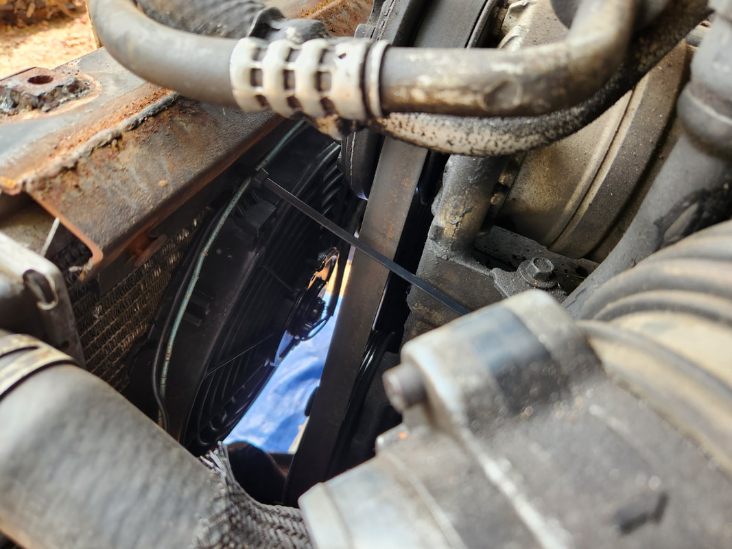
Original plan was to use a 16" fan but it was actually to big. Instead two 12" fans were able to fit perfectly on the inside radiator surface. The fans are secured with radiator fan zip ties and regular zip ties going through the fins on the rad core. Both sets of wires are hooked together with a double female plug and a central pair of wires are hooked to that plug, then routed along the left fender and to the firewall where they're hooked up to an automotive relay. A constant 12v power feed was sourced from the added circuit for the truck's 12v plug in the cab while the relay coil power has power from a wire routed through the firewall to the cab and plugged to a switched 12v power line on an unused plug.
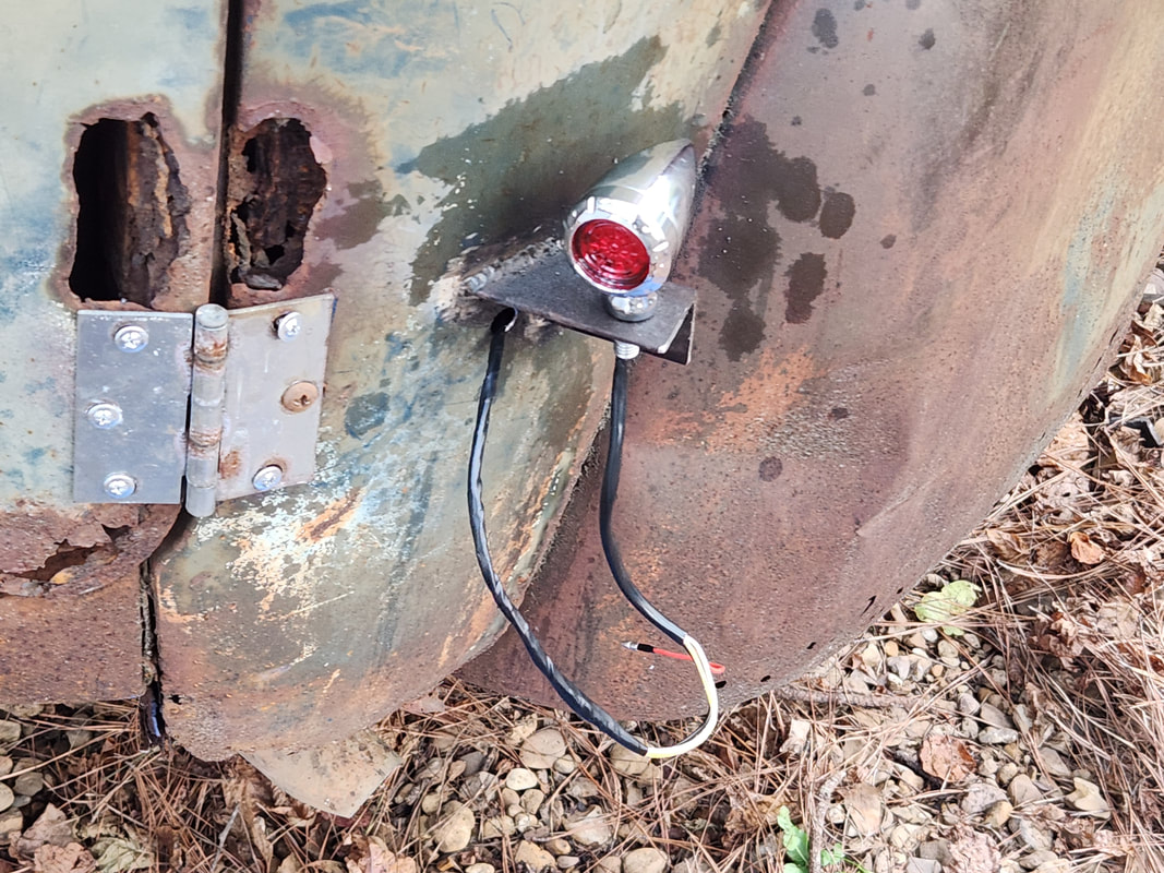
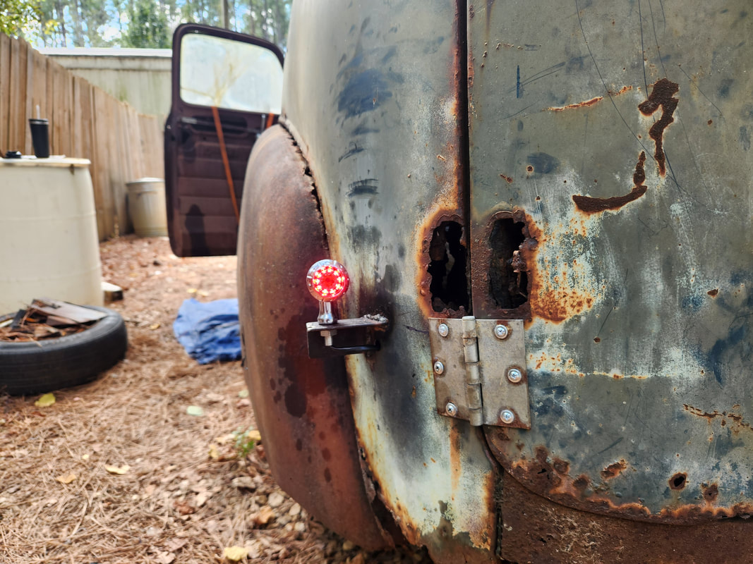
The bullet style taillights are mounted to angle iron bases welded to the side corners of the truck. The wiring is spliced into the S10 taillight wiring and routed through a hole in the body drilled just below the angle iron mounts to keep everything tucked away.
Because of an old electrical problem on the old S10, I was unable to use the stock brake light circuit for our new setup. First of all the power feeding the brake light for one reason or another is nonexistent, so I had to tap into another source of constant 12v power from the wire bundle coming from the interior fuse box. As for the output from the brake light switch, I ran a dedicated line to the back to hook up to the brake light side of our bullet lights. This does mean that our trailer lights only have taillight and turn signal light ability since the turn signals and brake lights are shared on those systems. In order to have working brake lights I would have to fabricate a dedicated set of brake lights that can be attached to a trailer along with the regular trailer lights and plugged up to a separate male/female plug setup on the rear of the truck. We won't worry about that as we're not going to be towing any trailers anytime soon. On a lighter note, I still had to add handles to the side doors and a hasp to the rear doors to keep them from flying open while driving down bumpy roads. I sourced this stuff from Walmart, using regular cabinet door handles and a rotating lock hasp. I also resurrected the license plate light, using the S10's old plate light plug and also set up the fuel filler door on the driver's side since the S10's fill port was on that side. With all that said and done, we still have to get some glass in this truck and try to weld the roof up since its separating all around the top of the body.
After running a separate line from the brake light switch to the rear, the two brake light portions of the bullet lights were hooked up, giving us functional brake lights. The issue on the old wiring has it where in standby, the left taillight is out and the right turn signal/brake light is constantly on. When the left turn signal is activated, the left taillight will come on while the left turn signal operates and the right turn signal/brake light will go off. When the right side is activated, the right turn signal will flash like normal while the left taillight stays on. The left brake light will not come on at all, so more than likely the problem is in the turn signal switch, but we're not about to tear all that apart at the moment.
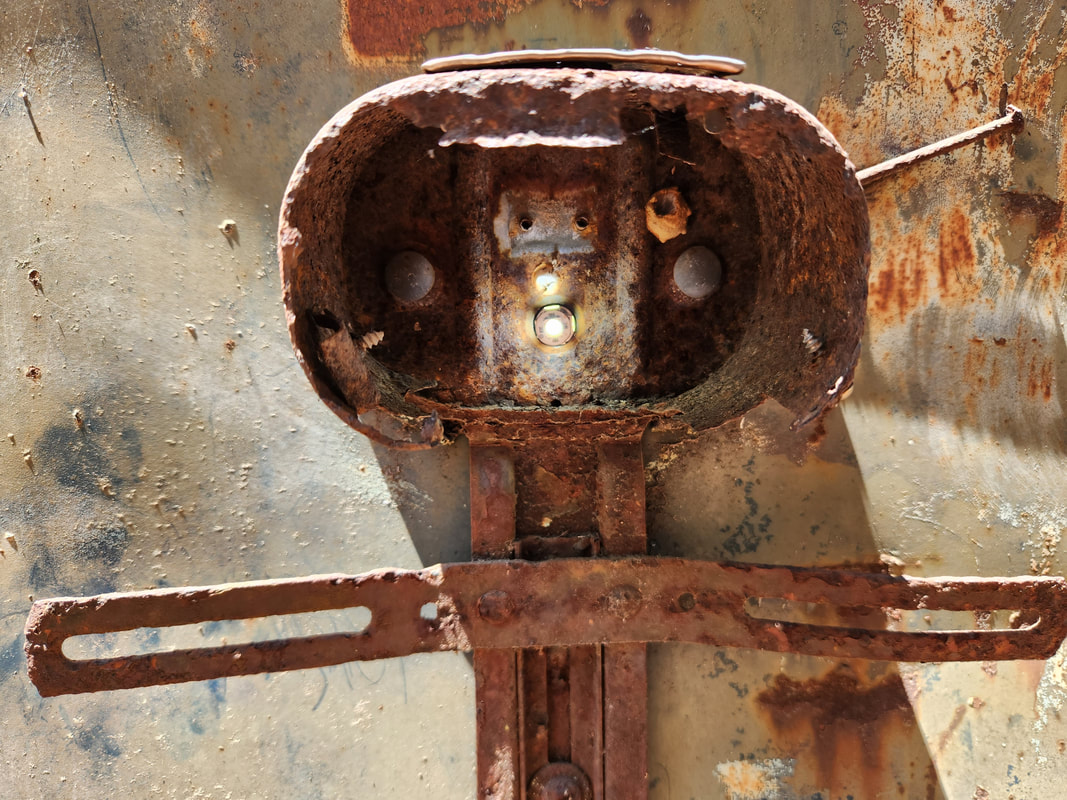
The license plate light was restored by cutting the plate light socket from the S10 wiring, adding a length of 2 conductor wire from that cut, then routing the 2 conductor wire up through the panel and through the old hinge holes and into the door. The wire is spliced in with the light socket. The old light socket in the door was broken off and the grommet removed, leaving a hole that was just right to allow me to press in the light socket, allowing the bulb to protrude out over the plate area. An aftermarket LED bulb is used in place of the regular bulb.
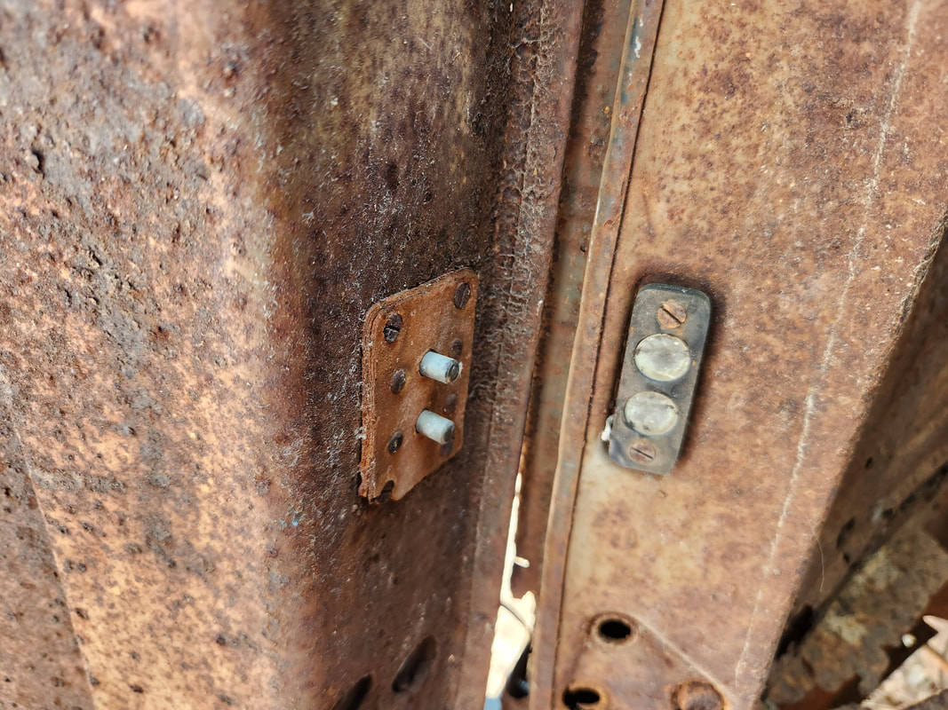
This little setup on the doors for the plate light is actually pretty cool. Incorporating two sets of contacts with one side being male, other side being more or less female, when the door is closed, the two meet, completing the circuit to allow the plate light to get power. This setup saves having to run wires through the area where they could get pinched. Of course this hardware is shot and will need to be fully replaced. At some point I would like to restore this setup and do away with the wire that I currently have passing through the old hinge holes on the body and door.
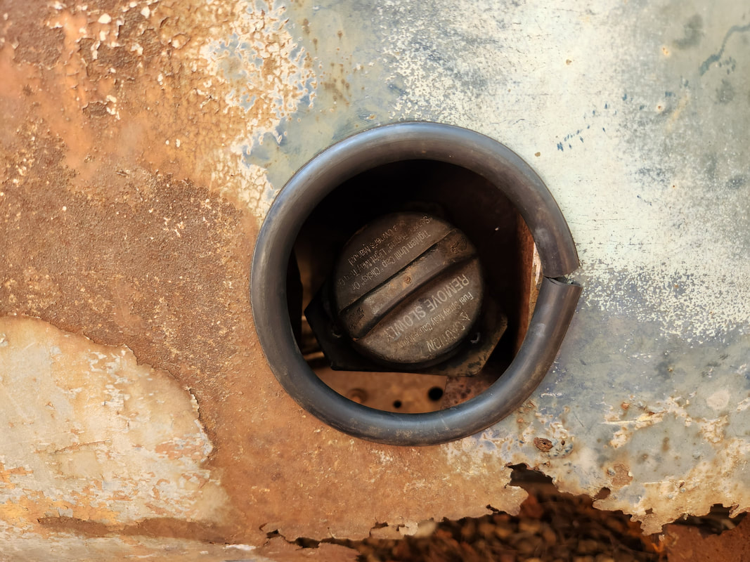
I had to cut an inner panel behind the outer panel to allow the filler tube to be raised up higher to reach this point. The flap of metal left from that cut provided an anchor point for a zip tie to hold the filler tube stationary as well. A 3" cut off grinder was used to cut this circular hole, which was then covered with a length of hose split lengthwise to be glued in place over the sharp edges of the hole. The filler tube/cap is centered in the hole where one can safely place their hand through the hole to remove/replace the cap.
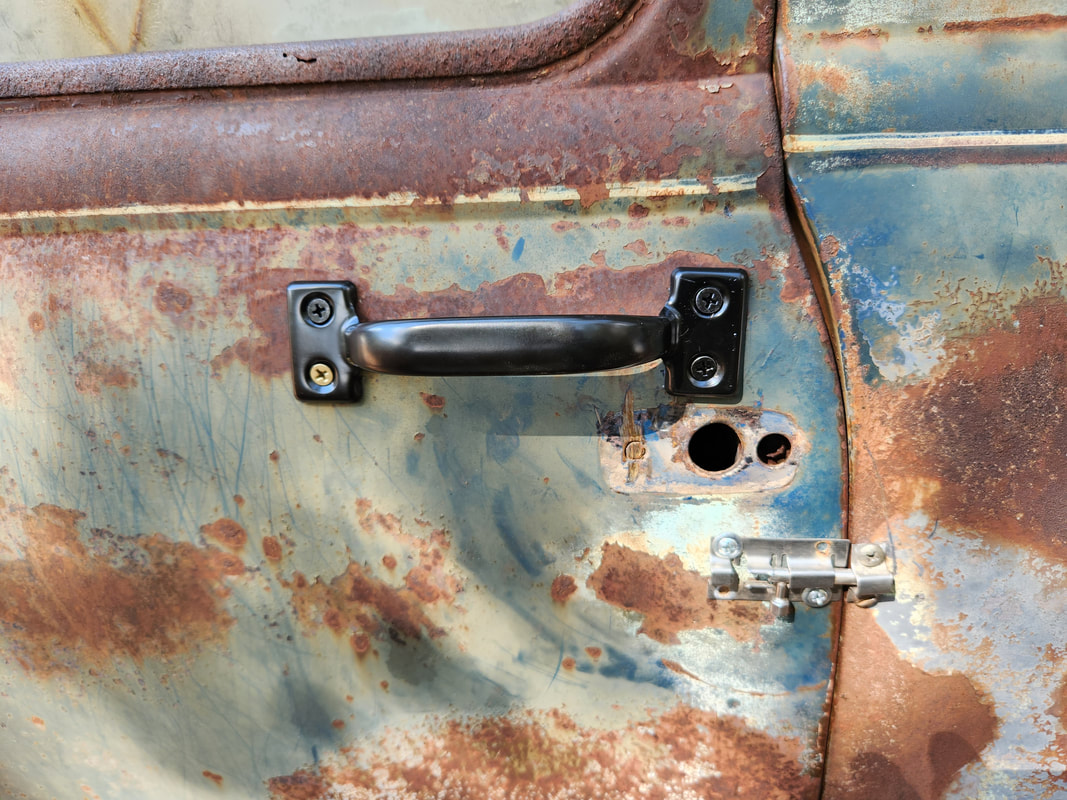
Cheap cabinet door handles were used on the side doors to allow for opening/closing without having to grab the door in an awkward spot. After getting this handle mounted, I duplicated the position on the other side, trying to keep things as symmetrical as possible.
Taking a moment to go back to the interior, I did manage to grab a battery box and power panels for installation. Luckily I already had a constant 12v power wire routed to the spot under the dash that was hooked up to the old S10 12v receptacle, so I would be able directly wire into the power panels. I did wire in a slim media player radio that I salvaged from another project, along with speakers that I pulled from the same vehicle, but unfortunately, the radio is flaky and only partially works, sometimes, so I will have to replace that device with a fresh unit. Going back outside, I went to the rear of the truck, installing a couple of latches that would ensure the two doors stay nicely secured to the body instead of bouncing around on the security latch that was installed first. I installed two latches as a redundant system for the doors so we shouldn't have any problems there. For a little humor, I did install the old S10 door badges on the 51's doors in order to better identify the truck for what it is. The biggest thing that I had to address was the missing glass on the right rear door and left windshield. Even though glass is available for the front, I would still have to source the rubber for the glass and the rear glass so far isn't easy to find. Plus, the rear door is so rusted that I would probably not be able to get the rubber solidly in place where the glass could be considered safe enough to not pop out. This is where plexiglass came in. After making templates out of cardboard, I sourced a cheap piece of plastic glass to cut the blanks out and glued the rear panel in with construction adhesive while carefully working the front panel in place into the rubber bushing. These temporary measures are to buy me some time to be able to source the proper hardware to install regular glass and rubber on the front.
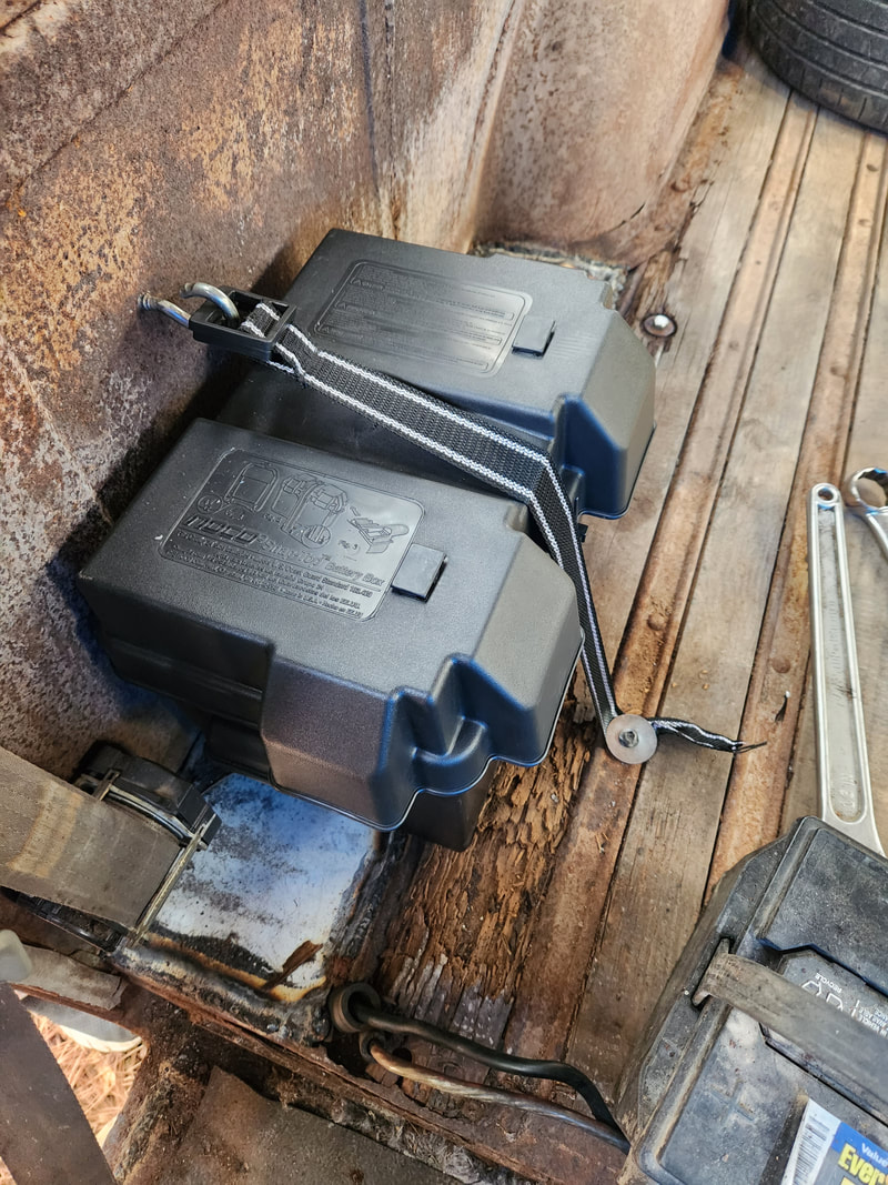
The battery box, used normally for trolling motor batteries, is bolted to the floor with a couple nuts and bolts with fender washers. The strap that came with the box is bolted to the floor with a self tapping screw while being hooked, rather crudely, to a hook bolt above the box, to hold the lid on as well as secure the whole thing from bouncing excessively. The current battery is a side post battery and unable to be used on this box so I will have to change to a top post battery before I can fully secure the unit in the box.
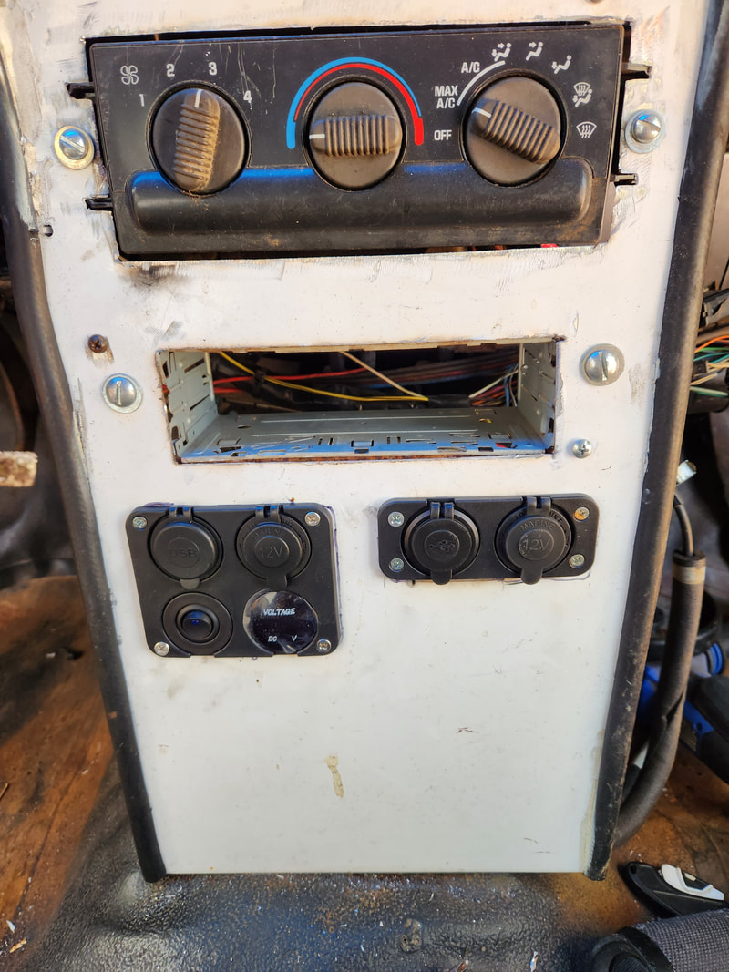
Two power panels are installed on the central sheet metal panel. Both panels have a dual USB port and 12v receptacle, with the larger unit also holding a voltmeter and auxiliary switch for added devices. Both panels are wired to the constant 12v line that is fed to the under-dash area. This same power source also supplies the constant 12v feed for the radio.
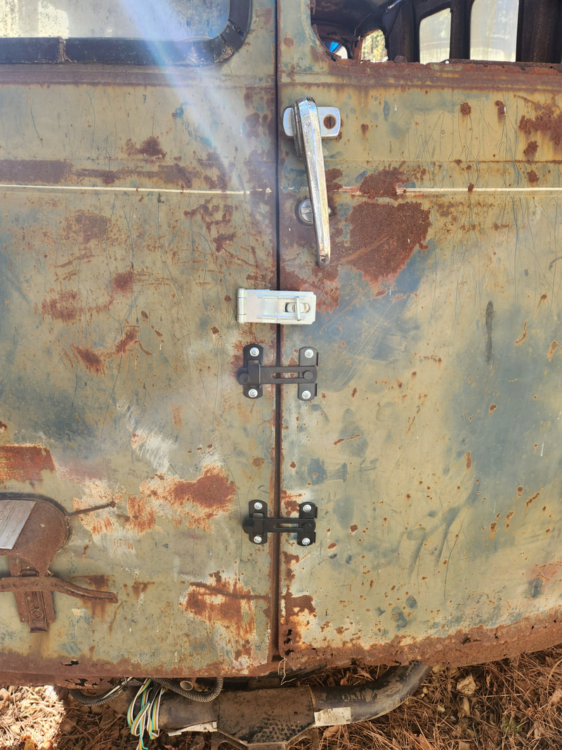
Even though this rotating hasp keeps the two rear doors from opening, it still allows the door to be pulled slightly open, which will cause excessive bouncing of the two doors while in motion. In addition to the security latch on the two doors, I installed this pair of lever latches that when secured, holds the door firmly to the body. Two latches serves as a redundant system as one can fail and still hold the doors together.
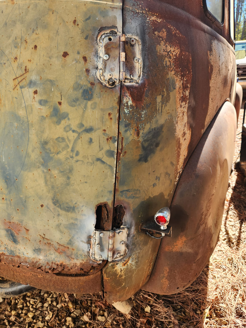
Against my previous plans, I welded up the hinges on both doors as the self tapping screws are working themselves loose some when the doors are opened and closed. This isn't good as this could allow the doors to fly off with the right bump. This also allows the doors to stay firmly planted to the body along with the latches. Since the body and the doors both are ratty, welding onto this really doesn't hurt anything.
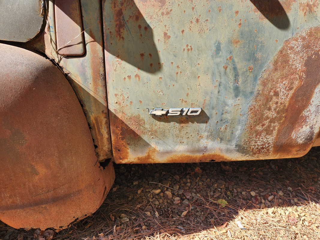
A nice conversation starter will be these door badges I glued in place on the 51's doors. These were pulled from the S10's old doors. Anyone who is remotely interested in cars will probably question why this "old" truck has S10 badges and understand when they get the whole background story of this truck.
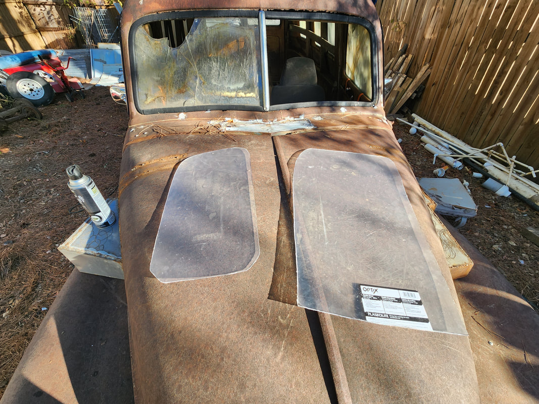
As a temporary measure for the missing glass, I sourced a plexiglass panel for use in cutting out a couple window panels. I made templates with cardboard then traced the outlines on the raw panel. Using a rotary tool and cutoff wheel, I cut these panels out.
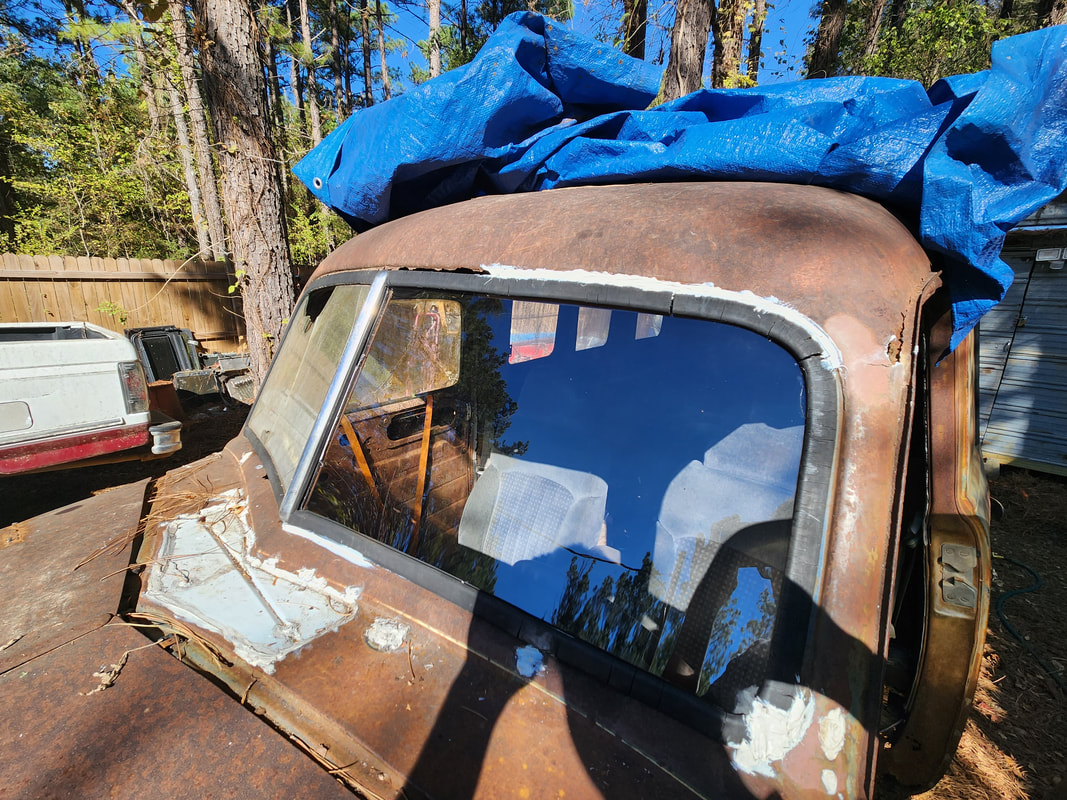
Since the rubber bushing is still in place on the windshield area, the panel I cut had to be carefully worked into the groove all around the window opening. I had to cut the rubber in spots since the hardened dry rotted rubber is harder to manipulate. I also had to trim a little more of the edges of the glass to better work the glass in place. Even with all this care, near the end, I still chipped a small piece from the panel. At least when the glass was fully worked into the rubber, the chipped piece was mostly covered by the groove on the rubber. Because the panel is thinner than the stock glass, I'll have to apply silicone caulk into the groove around the edges of the glass to further seal the glass and secure it so the glass doesn't bounce around in place. I also had to apply liberal amounts of the remaining construction adhesive to the rusted area above the windows since there's no way for me to weld this section of the roof back down with it being so close to the rubber and the glass. I'll have to apply more adhesive to the rest of the area to fully fill in the rusted openings around the window. Also note the lower right corner of the window where more glue was applied to fill in rust openings and gaps.
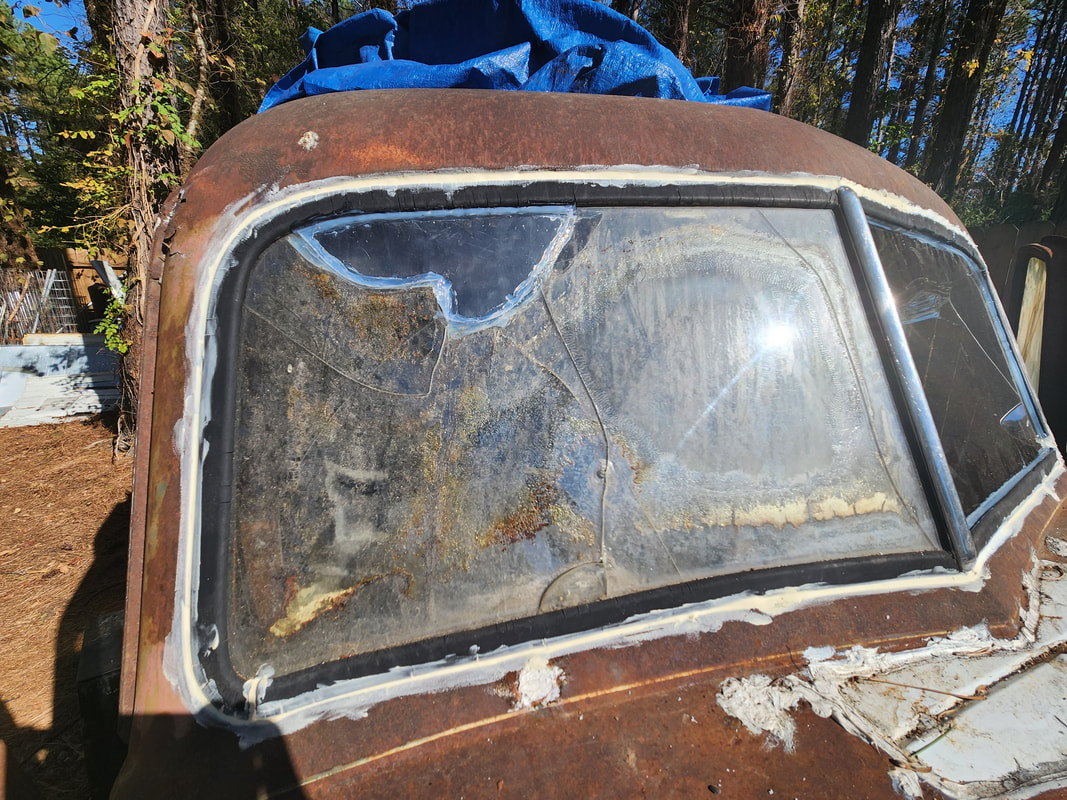
Construction adhesive is applied around the outer edges of the rubber on the windows to seal the gaps around the rubber where water can collect and further rust the metal just under the rubber. Even where the rubber was cracked, adhesive was applied. I also took a moment to cut an odd shaped piece of leftover plexiglass to fill the opening in the broken passenger side window, sealing the joints with silicone caulk, including in the groove of the rubber gasket. As cheesy as this may be, this is a temporary step to seal everything before we can get replacement glass and rubber for the windshield.
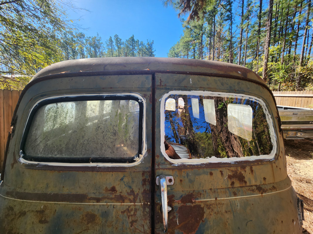
Since the rear door is extremely rusty around the window opening, installing stock rubber would probably not be effective in holding itself much less the stock glass in place. Here, the plexiglass panel is glued in using construction adhesive. A bead is applied around the opening and the panel pressed in place. Because of the slight curvature of the door, I had to wedge a length of PVC pipe to the right side to hold the panel firm against the door. From there I applied more glue around the gaps between the edge of the panel and the flared opening on the door. I worked the glue in to ensure all gaps are fully filled so when the stuff dries, this area should not leak at all. Can't say the same for all the other rusted out openings and areas around the rear however. Next, adhesive is applied around the outer edges of the rubber on the rear window as well to further seal the left side since the right side suffered the same fate we're trying to prevent, which is rusting away under where the rubber sat.
With both windows front and back fully covered with adhesive and caulk around the inner and outer parts of the rubber gaskets, I moved on to the hood. I had to figure out a way to secure the hood that would still allow for relatively quick removal. First part involved adding bolts up through the body which would serve as studs. Holes drilled in the hood allow for the rear of the hood to fit over the studs and are then locked down with salvaged lawnmower arm wing nuts. At the front, I still had the latch lever on the hood itself, but the portion of the hood latch/release being gone, had to be substituted. This was done with a bolt welded into a support member that held the old latch hardware. This allowed for the lever latch to catch the bolt to hold the hood down. Because of the distortion of the hood, there was still some room for play that would allow me to push the hood down to release the latch. As a redundancy, I bolted a couple of heavy bungee straps to the front corners of the hood then just hooked the other end to the fronts of the S10 frame rails. If the latch did pop loose, the bungees would still hold the hood down. With that, I fired up the truck and topped off the transmission before putting the truck on the road. I kept the speeds relatively conservative, only hitting 50mph at times. The transmission was surprisingly cooperative and the only real noise from the old body was from the rear doors which rattled and bounced in their place. After the test I did find that one of the transmission line fittings in the radiator were leaking heavily during driving, causing the loss of oil from previous engine running. I will have to remedy that problem later, along with the rear doors, which may incorporate the use of scrap hose to serve as cushioning around the door frame. There are still other things that will need to be done to fine tune the truck and just overall make the truck better and more comfortable, comparable to the original S10 truck this thing is built on.
To hold down the rear of the hood, two bolts were applied through holes drilled in the body just under the hood. Nuts hold the bolts in place, turning the bolts into studs. Holes drilled in the hood allow for the rear of the hood to sit on the studs, which are then topped with wing nuts salvaged from a lawnmower handle.
Since the lever latch is still present on the hood, I welded a 3/8" bolt in a hole drilled in the support member from the old latch hardware. This bolt is hooked by the lever latch. Enough play is present in the hood to allow the hood to be pushed down enough to release the latch.
Two heavy bungee cords are bolted to holes drilled in the corners of the hood. The S-hooks on the other ends of the straps allow for hooking to the front of the S10 frame rails to hold the front of the hood down in case the latch released for any reason.
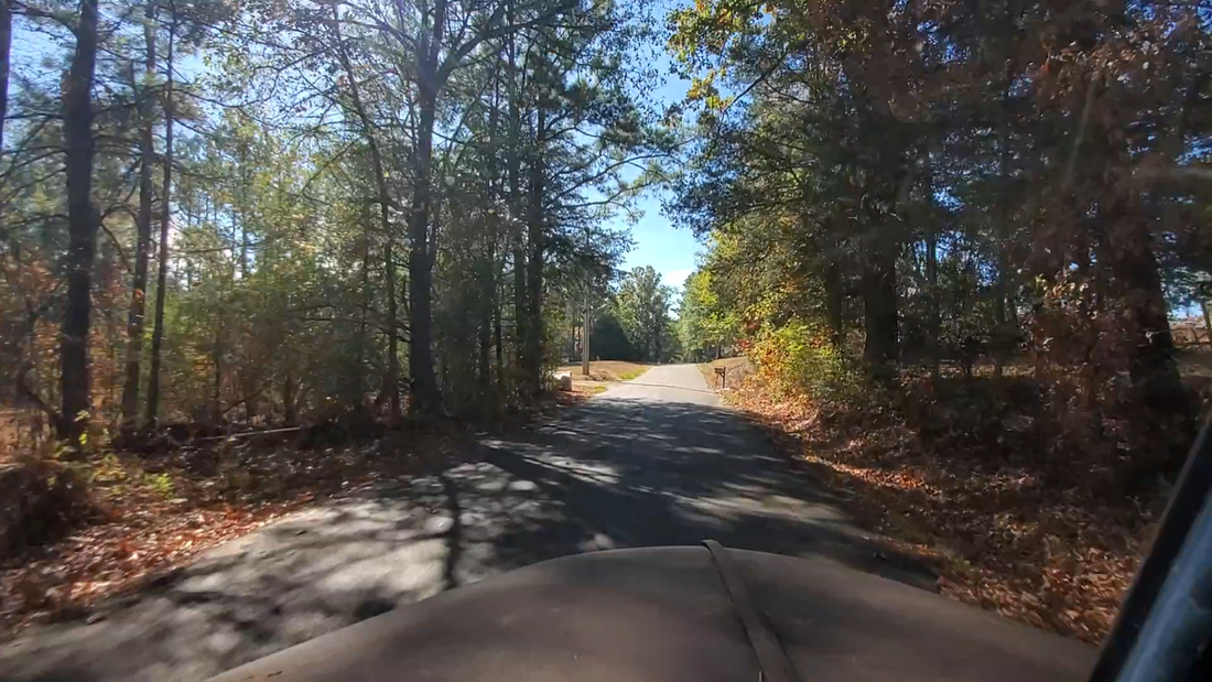
A test drive around our area pointed out some of the bugs that have to be weeded out, mainly the idea the transmission line fittings need replacing and some form of cushioning needs to be added around the rear door frames to quiet them down.
